EP0284591A1 - Verfahren zum Abtrennen eines gebrochenen Kettenfadens aus dem Kettenfell an einer Webmaschine und Vorrichtung zur Durchführung dieses Verfahrens - Google Patents
Verfahren zum Abtrennen eines gebrochenen Kettenfadens aus dem Kettenfell an einer Webmaschine und Vorrichtung zur Durchführung dieses Verfahrens Download PDFInfo
- Publication number
- EP0284591A1 EP0284591A1 EP88870044A EP88870044A EP0284591A1 EP 0284591 A1 EP0284591 A1 EP 0284591A1 EP 88870044 A EP88870044 A EP 88870044A EP 88870044 A EP88870044 A EP 88870044A EP 0284591 A1 EP0284591 A1 EP 0284591A1
- Authority
- EP
- European Patent Office
- Prior art keywords
- warp
- characteristic
- nozzles
- fallen
- suction nozzle
- Prior art date
- Legal status (The legal status is an assumption and is not a legal conclusion. Google has not performed a legal analysis and makes no representation as to the accuracy of the status listed.)
- Granted
Links
- 238000000034 method Methods 0.000 title claims abstract description 47
- 238000009941 weaving Methods 0.000 title claims abstract description 9
- 238000000605 extraction Methods 0.000 claims description 6
- 230000004913 activation Effects 0.000 claims description 5
- 230000007246 mechanism Effects 0.000 claims description 5
- 230000007723 transport mechanism Effects 0.000 claims description 5
- 230000009471 action Effects 0.000 claims description 4
- 230000002250 progressing effect Effects 0.000 claims description 2
- 230000003213 activating effect Effects 0.000 claims 6
- 230000009849 deactivation Effects 0.000 description 2
- 230000000694 effects Effects 0.000 description 2
- 230000008569 process Effects 0.000 description 2
- 238000007665 sagging Methods 0.000 description 2
- 230000008901 benefit Effects 0.000 description 1
- 230000008439 repair process Effects 0.000 description 1
- 230000000284 resting effect Effects 0.000 description 1
- 230000032258 transport Effects 0.000 description 1
Images





Classifications
-
- D—TEXTILES; PAPER
- D03—WEAVING
- D03J—AUXILIARY WEAVING APPARATUS; WEAVERS' TOOLS; SHUTTLES
- D03J1/00—Auxiliary apparatus combined with or associated with looms
- D03J1/004—Detection and repair of broken warp yarns
-
- D—TEXTILES; PAPER
- D03—WEAVING
- D03D—WOVEN FABRICS; METHODS OF WEAVING; LOOMS
- D03D51/00—Driving, starting, or stopping arrangements; Automatic stop motions
- D03D51/18—Automatic stop motions
- D03D51/20—Warp stop motions
Definitions
- This invention concerns a method for separating a broken warp thread at the warp stop motion from the warp sheet on a weaving machine - in particular on weaving machines of the type in which the warp stop motion consists of one or more rows of drop wires - in order to enable the broken warp thread to be automatically located and taken up.
- the invention also concerns a device which uses this method.
- a warp stop motion commonly used on weaving machines consists of a row of drop wires resting on the warp threads, so that when a warp thread break occurs, the corresponding drop wire makes an electrical contact or mechanical interlock, thus causing the machine to be stopped.
- Dutch patent application No. 8600372 - made by the present applicant - describes a method of automatically locating the fallen drop wire, which is then gripped and raised in order to make it visibly stand out from the row of drop wires, thus enabling the weaver to see at a glance where a thread break needs to be repaired.
- Dutch patent application No. 8601819 also describes a method for turning the fallen drop wire through an angle so that the neighboring drop wires are forced apart, thus forming a local opening in the unbroken warp threads, and so facilitating rethreading of the drop wire which is presented in this way.
- the present invention concerns a method for separating the broken warp thread at the warp stop motion from the warp sheet on a weaving machine, thus providing a solution to the problem described below. Further, the warp thread which is thus separated is also brought into the correct position with respect to the remaining warp threads, in other words not crossed over the neighboring threads.
- the method of the invention essentially involves extracting the sagging loop - formed in the broken warp thread as a result of the drop wire falling - from the warp stop motion, back from the fallen drop wire; optionally, the fallen drop wire may first be raised before extracting the broken warp thread in this way.
- the loop is extracted from the warp stop motion back from the fallen drop wire by means of at least one airstream which exerts a force on the broken warp thread, starting at the point where the fallen (or raised) drop wire is located.
- the airstream may be provided by suction or blower nozzles.
- the force is exerted by mechanical means, for example grippers or hooks.
- the method according to the present invention should preferably be used in combination with the method described in Dutch patent application No. 8601819, in which as well as being raised the fallen drop wire is also turned through an angle in order to facilitate the freeing of the broken warp thread.
- the effect of turning the drop wire in this way is to draw the neighboring warp threads away from the broken warp thread.
- the present invention also concerns a device for applying the method of the invention, which essentially uses one or more suction nozzles, blower nozzles or mechanical means which operate in conjunction with the drop wire.
- Fig. 1 shows a cross section of a warp stop motion consisting essentially of a number of rows of drop wires 1 to 4 which are suspended on the warp threads of the warp sheet 5, and which when they fall make an electrical contact with one the electrodes 6 to 9 respectively.
- the warp sheet 5 is led over supporting elements 10 to 14 on either side of the rows of drop wires 1 to 4.
- a broken warp thread 15 is shown such that the corresponding drop wire 16 has fallen. Also in fig. 1 there is a gripping device 17, more particularly as described in Dutch patent application No. 8601819, which manipulates the fallen drop wire 16.
- the actual mechanism of the invention consists, in the embodiment illustrated, of a series of suction nozzles 18 to 21 which can move in such a way that each suction nozzle 18 to 21 can be presented opposite one of a particular row of drop wires 1 to 4.
- the operation of the device according to the invention, using the method outlined above, is described below with the aid of the successive figures.
- the fallen drop wire 16 is gripped by its end 23, turned and raised by gripping device 17, as shown in fig. 2.
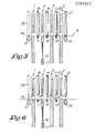
- the suction nozzles 18 to 21 are lowered towards the warp sheet 5, almost right up to the supporting elements 11 to 14, as shown in fig. 3.
- the result of raising the fallen drop wire 16 will be that where previously there was a sag 22 in the warp thread 15 there will now be a free-hanging loop 24.
- the suction nozzle 19 is activated, with the result that the warp thread 15 is drawn taut and perhaps also partly sucked in.
- the suction nozzles 18 to 21 are now moved upwards, with the result that said loop 24 is displaced over a short distance, arriving over the supporting element 12, since the suction nozzle 19 drags the warp thread 15 towards it.
- suction nozzle 19 When the nozzles arrive in their highest position, suction nozzle 19 is deactivated and suction nozzle 20 is activated (the activation and deactivation times may overlap slightly).
- the series of suction nozzles is once more presented to the warp sheet 5, resulting in a situation as shown in fig. 5.
- the warp thread 15 is then moved along by the action of suction nozzle 20, so that the loop is farther displaced to nozzle 20, as shown in fig. 6.
- a hooking or gripping mechanism 25 may be positioned in proximity to the last suction nozzle 21 in order to take over the warp thread 15 from the suction nozzle 21, so that the latter may be deactivated. Said hooking or gripping mechanism 25 may then be used for further manipulation of the warp thread 15; however such manipulation is outwith the scope of this invention.
- suction nozzle which is first lowered beside the fallen drop wire 16, then activated and raised so as to draw the loop 24 with it, and subsequently deactivated and positioned over the following row of drop wires. This sequence is repeated until the suction nozzle arrives outside the warp stop motion, at which point the abovementioned hooking or gripping mechanism 25 can take over the thread.
- the device in addition to the suction nozzles, the device must include the necessary transport, activation, deactivation and control functions necessary for the cycle to be carried out automatically.
- the loop 24 can of course be carried either to side 26 or side 27 of the warp stop motion; in the latter case, there must be another suction nozzle 28 at the other side 27 of the warp stop motion.
- the operating cycle of the suction nozzles 18 to 21 is as follows. When a warp break is detected, all the suction nozzles 18 to 21 are lowered. The suction nozzle nearest the fallen drop wire 16 is activated and raised so that the broken warp thread 15 is raised with it; in the accompanying figures, the suction nozzles concerned would be nozzle 19. When the suction nozzle 19 arrives in its raised position, it is deactivated and the next suction nozzle 20, which is still in the lowered position, is activated and then raised. This process is repeated in a similar way until the loop 24 has been carried out of the warp stop motion.
- suction nozzles are then activated and deactivated successively, so that the loop 24 is passed from one to the other until it arrives outside the warp stop motion, either on side 26 or on side 27, in other words going directly from the stage shown in fig. 4 to the stage shown in fig. 6, without moving the suction nozzles up and down.
- a warp thread which gets stuck in a nozzle can also be freed by some mechanical device, eg. rings or tubes 29 mounted concentrically on the suction nozzles 18 to 21 and which move up and down.
- suction nozzles 18 to 21, and also nozzle 28 if provided, can also be mounted underneath the warp sheet 5 instead of above it.
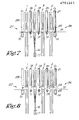
- the method of the invention is accomplished by using a succession of airjets at various points to displace the loop 24 in the broken warp thread 15, starting at the fallen drop wire 16 and progressing to one of the sides of the warp stop motion, in this case side 26.
- the suction nozzles 18 to 21, and nozzle 28 if provided, are replaced to blower nozzles 30 to 34. No up and down motion is necessary if such blower nozzles are used.
- the operation of the device may be simply deduced from fig. 10, and is more or less analagous to the method using suction nozzles.
- extraction tubes 35 to 39 mounted opposite the blower nozzles 30 to 34, in order to promote evacuation of the airstream from whichever blower nozzles are activated.
- the extraction tubes may also operate as suction nozzles, so that there is a combined action of blower and suction nozzles.
- blower nozzles 30 to 33, and also blower nozzle 34 if provided, are mounted underneath the warp sheet 5. This has the advantage that they can be mounted on the same transport mechanism as the rotatable gripper device 17.
- the loop 24 can also be transported out of the warp stop motion by means of hooking or gripping devices.
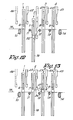
- the suction nozzles are replaced by hooks 42 to 45, and also hook 46 if provided, which move up and down, thus raising the loop 24, starting at the fallen drop wire 16.
- the particularity of this method is that, as shown in the two figures, it is not necessary for the fallen drop wire 16 to be presented and raised by a special gripping device 17, since the corresponding drop wire will be raised by the action of gripper 43 in fig. 13.
- the motion of the hooks must of course be controlled in such a way that they operate separately one after the other so that they carry the loop 24 in the warp thread 15 with them. In order to avoid unwanted effects on the loop 24, it is also possible for a guide 47 for the broken warp thread to be lowered.
- suitably controlled gripping or clamping devices may be used instead of the hooks 42 to 45.
- the hooking, gripping or clamping devices may of course also be mounted under the warp sheet 5.
- the suction nozzles 18 to 21 or the suction nozzle 28 may be provided with a sieve-shaped element 48 which prevents the broken warp thread 15 being sucked completely into the suction nozzles 18 to 21 or 28.
- the extraction tubes 35 to 39 may also be provided with a sieve-shaped element 48 which prevents the broken warp thread 15 being blown completely into the extraction tubes 35 to 39.
- the sieve-shaped element 48 may be provided with holes 49 whereby the diamter of the holes 49 is less than the diameter of the warp thead 15 in order to prevent the warp thread being sucked into the holes 49.
Landscapes
- Engineering & Computer Science (AREA)
- Textile Engineering (AREA)
- Auxiliary Weaving Apparatuses, Weavers' Tools, And Shuttles (AREA)
- Looms (AREA)
- Treatment Of Fiber Materials (AREA)
Applications Claiming Priority (2)
| Application Number | Priority Date | Filing Date | Title |
|---|---|---|---|
| BE8700254A BE1000376A4 (nl) | 1987-03-13 | 1987-03-13 | Werkwijze voor het ter hoogte van de kettingwachter afzonderen van een gebroken kettingdraad uit de ketting bij een weefmachine, alsook inrichting die deze werkwijze toepast. |
| BE8700254 | 1987-03-13 |
Publications (2)
| Publication Number | Publication Date |
|---|---|
| EP0284591A1 true EP0284591A1 (de) | 1988-09-28 |
| EP0284591B1 EP0284591B1 (de) | 1991-05-29 |
Family
ID=3882562
Family Applications (1)
| Application Number | Title | Priority Date | Filing Date |
|---|---|---|---|
| EP88870044A Expired EP0284591B1 (de) | 1987-03-13 | 1988-03-10 | Verfahren zum Abtrennen eines gebrochenen Kettenfadens aus dem Kettenfell an einer Webmaschine und Vorrichtung zur Durchführung dieses Verfahrens |
Country Status (4)
| Country | Link |
|---|---|
| US (2) | US4905737A (de) |
| EP (1) | EP0284591B1 (de) |
| BE (1) | BE1000376A4 (de) |
| DE (1) | DE3862976D1 (de) |
Cited By (4)
| Publication number | Priority date | Publication date | Assignee | Title |
|---|---|---|---|---|
| EP0421924A1 (de) * | 1989-10-03 | 1991-04-10 | Sulzer RàTi Ag | Verfahren und Einrichtung zur Behebung von Kettfadenbrüchen in einer Webmaschine |
| EP0364404A3 (de) * | 1988-10-10 | 1991-08-07 | Texipat S.A. | Vorrichtung und Verfahren zum automatischen Reparieren von gebrochenen Kettfäden in Webmaschinen |
| EP0508514A1 (de) * | 1991-04-09 | 1992-10-14 | Picanol N.V. | Verfahren und Vorrichtung um das Ende eines gebrochenen Kettfadens von der Kette in einer Webmaschine zu isolieren |
| EP2570530A1 (de) * | 2011-09-14 | 2013-03-20 | Starlinger & Co Gesellschaft m.b.H. | Kettbändchenwächter und Rundwebmaschine |
Families Citing this family (6)
| Publication number | Priority date | Publication date | Assignee | Title |
|---|---|---|---|---|
| EP0381143B1 (de) * | 1989-02-02 | 1996-05-29 | Tsudakoma Corporation | Verfahren und Vorrichtung zum automatischen Reparieren eines Kettfadens |
| JPH06104946B2 (ja) * | 1989-10-11 | 1994-12-21 | シーケーディ株式会社 | ドロッパの分離装置 |
| DE69115319T2 (de) * | 1990-03-28 | 1996-05-02 | Tsudakoma Ind Co Ltd | Verfahren zur Lokalisierung der einem gebrochenen Kettenfaden entsprechenden Lücke in einem Webblatt sowie Lokalisierungs- bzw. Einziehvorrichtung |
| KR930004078B1 (ko) * | 1990-03-28 | 1993-05-20 | 쯔다고마 고오교오 가부시끼가이샤 | 수복(修腹)후의 경사의 처리방법 |
| JP2832857B2 (ja) * | 1990-04-19 | 1998-12-09 | 津田駒工業株式会社 | たて糸修復用制御方法およびその装置 |
| JP5216990B2 (ja) * | 2005-11-21 | 2013-06-19 | ピカノール | エアージェット式織機によこ糸を導入する方法とエアージェット式織機 |
Citations (2)
| Publication number | Priority date | Publication date | Assignee | Title |
|---|---|---|---|---|
| NL68526C (de) * | ||||
| FR1467135A (fr) * | 1965-12-13 | 1967-01-27 | Cotonniere De Fives | Casse-chaîne électrique perfectionné pour métier à tisser |
Family Cites Families (9)
| Publication number | Priority date | Publication date | Assignee | Title |
|---|---|---|---|---|
| DE2902003C2 (de) * | 1979-01-19 | 1986-08-28 | W. Schlafhorst & Co, 4050 Mönchengladbach | Tufting-Maschine mit einer Einrichtung zum Verlängern der zugeführten Fadenschar |
| US4300599A (en) * | 1980-01-04 | 1981-11-17 | Leesona Corporation | Warp detection system |
| DE3143484C2 (de) * | 1981-11-03 | 1983-09-29 | Lindauer Dornier Gmbh, 8990 Lindau | Vorrichtung zum Vereinzeln von Weblitzen oder Lamellen |
| NL8202215A (nl) * | 1982-06-01 | 1984-01-02 | Rueti Te Strake Bv | Spoelloze weefmachine, voorzien van middelen voor het uit het weefvak verwijderen van defecte inslagdraden. |
| EP0104298B1 (de) * | 1982-09-24 | 1987-04-01 | GebràDer Sulzer Aktiengesellschaft | Vorrichtung zur logistischen Bedienung von Textilmaschinen |
| JPS609952A (ja) * | 1983-06-29 | 1985-01-19 | 株式会社豊田自動織機製作所 | 織機における切断経糸処理方法 |
| NL8600372A (nl) * | 1986-02-14 | 1987-09-01 | Picanol Nv | Inrichting voor het bepalen van de plaats van een kettingbreuk bij weefmachines met kettingwachterlamellen. |
| DE3764218D1 (de) * | 1986-07-08 | 1990-09-13 | Picanol Nv | Verfahren und vorrichtung zum vereinfachen der reparatur eines kettfadens in webmaschinen mit abstellamellen. |
| NL8602192A (nl) * | 1986-08-28 | 1988-03-16 | Picanol Nv | Werkwijze voor het herstellen van een kettingbreuk bij weefmachines en herbedradingsinrichtingen hierbij aangewend. |
-
1987
- 1987-03-13 BE BE8700254A patent/BE1000376A4/nl not_active IP Right Cessation
-
1988
- 1988-03-10 EP EP88870044A patent/EP0284591B1/de not_active Expired
- 1988-03-10 DE DE8888870044T patent/DE3862976D1/de not_active Expired - Lifetime
- 1988-03-14 US US07/167,906 patent/US4905737A/en not_active Expired - Fee Related
-
1989
- 1989-11-21 US US07/439,871 patent/US4967801A/en not_active Expired - Fee Related
Patent Citations (2)
| Publication number | Priority date | Publication date | Assignee | Title |
|---|---|---|---|---|
| NL68526C (de) * | ||||
| FR1467135A (fr) * | 1965-12-13 | 1967-01-27 | Cotonniere De Fives | Casse-chaîne électrique perfectionné pour métier à tisser |
Cited By (8)
| Publication number | Priority date | Publication date | Assignee | Title |
|---|---|---|---|---|
| EP0364404A3 (de) * | 1988-10-10 | 1991-08-07 | Texipat S.A. | Vorrichtung und Verfahren zum automatischen Reparieren von gebrochenen Kettfäden in Webmaschinen |
| EP0421924A1 (de) * | 1989-10-03 | 1991-04-10 | Sulzer RàTi Ag | Verfahren und Einrichtung zur Behebung von Kettfadenbrüchen in einer Webmaschine |
| EP0421923A1 (de) * | 1989-10-03 | 1991-04-10 | Sulzer RàTi Ag | Verfahren und Einrichtung zum Einziehen eines Kettfadens in gewebebildende Teile einer Webmaschine |
| EP0508514A1 (de) * | 1991-04-09 | 1992-10-14 | Picanol N.V. | Verfahren und Vorrichtung um das Ende eines gebrochenen Kettfadens von der Kette in einer Webmaschine zu isolieren |
| BE1004740A3 (nl) * | 1991-04-09 | 1993-01-19 | Picanol Nv | Werkwijze en inrichting voor het afzonderen van een draadeinde van een gebroken kettingdraad uit de ketting bij een weefmachine. |
| US5249606A (en) * | 1991-04-09 | 1993-10-05 | Picanol N.V., Naamloze Vennootschap | Isolating a yarn end of a broken warp thread from the warp in a weaving machine |
| EP2570530A1 (de) * | 2011-09-14 | 2013-03-20 | Starlinger & Co Gesellschaft m.b.H. | Kettbändchenwächter und Rundwebmaschine |
| WO2013037631A1 (de) * | 2011-09-14 | 2013-03-21 | Starlinger & Co Gesellschaft M.B.H. | Kettbändchenwächter und rundwebmaschine |
Also Published As
| Publication number | Publication date |
|---|---|
| US4905737A (en) | 1990-03-06 |
| BE1000376A4 (nl) | 1988-11-16 |
| US4967801A (en) | 1990-11-06 |
| DE3862976D1 (de) | 1991-07-04 |
| EP0284591B1 (de) | 1991-05-29 |
Similar Documents
| Publication | Publication Date | Title |
|---|---|---|
| EP0284591B1 (de) | Verfahren zum Abtrennen eines gebrochenen Kettenfadens aus dem Kettenfell an einer Webmaschine und Vorrichtung zur Durchführung dieses Verfahrens | |
| AU646496B2 (en) | Device for handling healds or drop wires in a warp thread insertion machine | |
| US4815498A (en) | Process and apparatus for manipulating fallen drop wires of weaving loom warp stop motions and facilitating repair of broken warp threads | |
| US4909283A (en) | Tucking-in device for weaving machines | |
| US4915144A (en) | Delivering yarns with an excess length from a yarn store in an air jet multicolor loom | |
| JPH0735625B2 (ja) | たて糸の切れ端分離方法およびその装置 | |
| ITPI960032A1 (it) | Perfezionamenti ad un metodo e ad una apparecchiatura per l'imbrigliamento in corso di tessitura di porzioni terminali di filo | |
| US4140156A (en) | Weft strand positioning at the exit end of the shed in a weaving machine | |
| US5111560A (en) | Automatic warp threading apparatus | |
| CN217851512U (zh) | 一种假睫毛自动编织设备 | |
| EP0462926A1 (de) | Schussbruchbehebung bei Projektilwebmaschinen | |
| JPH10168694A (ja) | 糸交換型の整経機における 外された糸の迅速回収システム | |
| JP2665918B2 (ja) | たて糸自動補修方法およびその装置 | |
| US3803673A (en) | Device for removing yarn remainders from coil cores | |
| CN109881342A (zh) | 自动穿综机用上综丝行程套件 | |
| JPS6328951A (ja) | 経糸検出片を備えた織機の経糸修理を容易にする方法及びその実施に使用する装置 | |
| US5090454A (en) | Deweaving apparatus with pneumatic defective pick release for shuttle-type loom | |
| US3875973A (en) | Shed mechanism for a weaving machine | |
| US4798045A (en) | Process for splicing fibers in strips, and a machine for feeding a textile machine incorporating such a process | |
| DE69115319T2 (de) | Verfahren zur Lokalisierung der einem gebrochenen Kettenfaden entsprechenden Lücke in einem Webblatt sowie Lokalisierungs- bzw. Einziehvorrichtung | |
| US2808076A (en) | Looms having automatic bobbinchanging mechanism | |
| US5249606A (en) | Isolating a yarn end of a broken warp thread from the warp in a weaving machine | |
| US1931092A (en) | Method and apparatus for making pile fabrics | |
| EP0417849A1 (de) | Verfahren zum Entfernen des am Ende der Spulhülse geklemmten und aufgewickelten Garnteiles und eine Vorrichtung zum Durchführen des Verfahrens | |
| US4640315A (en) | Projectile weaving machine |
Legal Events
| Date | Code | Title | Description |
|---|---|---|---|
| PUAI | Public reference made under article 153(3) epc to a published international application that has entered the european phase |
Free format text: ORIGINAL CODE: 0009012 |
|
| AK | Designated contracting states |
Kind code of ref document: A1 Designated state(s): CH DE FR IT LI |
|
| 17P | Request for examination filed |
Effective date: 19881012 |
|
| 17Q | First examination report despatched |
Effective date: 19901025 |
|
| GRAA | (expected) grant |
Free format text: ORIGINAL CODE: 0009210 |
|
| AK | Designated contracting states |
Kind code of ref document: B1 Designated state(s): CH DE FR IT LI |
|
| REF | Corresponds to: |
Ref document number: 3862976 Country of ref document: DE Date of ref document: 19910704 |
|
| ITF | It: translation for a ep patent filed | ||
| ET | Fr: translation filed | ||
| PLBE | No opposition filed within time limit |
Free format text: ORIGINAL CODE: 0009261 |
|
| STAA | Information on the status of an ep patent application or granted ep patent |
Free format text: STATUS: NO OPPOSITION FILED WITHIN TIME LIMIT |
|
| 26N | No opposition filed | ||
| PGFP | Annual fee paid to national office [announced via postgrant information from national office to epo] |
Ref country code: FR Payment date: 19930212 Year of fee payment: 6 |
|
| PGFP | Annual fee paid to national office [announced via postgrant information from national office to epo] |
Ref country code: CH Payment date: 19930219 Year of fee payment: 6 |
|
| PGFP | Annual fee paid to national office [announced via postgrant information from national office to epo] |
Ref country code: DE Payment date: 19930310 Year of fee payment: 6 |
|
| PG25 | Lapsed in a contracting state [announced via postgrant information from national office to epo] |
Ref country code: LI Effective date: 19940331 Ref country code: CH Effective date: 19940331 |
|
| PG25 | Lapsed in a contracting state [announced via postgrant information from national office to epo] |
Ref country code: FR Effective date: 19941130 |
|
| REG | Reference to a national code |
Ref country code: CH Ref legal event code: PL |
|
| PG25 | Lapsed in a contracting state [announced via postgrant information from national office to epo] |
Ref country code: DE Effective date: 19941201 |
|
| REG | Reference to a national code |
Ref country code: FR Ref legal event code: ST |
|
| PG25 | Lapsed in a contracting state [announced via postgrant information from national office to epo] |
Ref country code: IT Free format text: LAPSE BECAUSE OF NON-PAYMENT OF DUE FEES;WARNING: LAPSES OF ITALIAN PATENTS WITH EFFECTIVE DATE BEFORE 2007 MAY HAVE OCCURRED AT ANY TIME BEFORE 2007. THE CORRECT EFFECTIVE DATE MAY BE DIFFERENT FROM THE ONE RECORDED. Effective date: 20050310 |