EP0284643A1 - Godet rotatif grillagé pour la séparation en fonction de leur grosseur des particules d'un matériau - Google Patents
Godet rotatif grillagé pour la séparation en fonction de leur grosseur des particules d'un matériau Download PDFInfo
- Publication number
- EP0284643A1 EP0284643A1 EP87106349A EP87106349A EP0284643A1 EP 0284643 A1 EP0284643 A1 EP 0284643A1 EP 87106349 A EP87106349 A EP 87106349A EP 87106349 A EP87106349 A EP 87106349A EP 0284643 A1 EP0284643 A1 EP 0284643A1
- Authority
- EP
- European Patent Office
- Prior art keywords
- bucket
- rotation
- sides
- axis
- products
- Prior art date
- Legal status (The legal status is an assumption and is not a legal conclusion. Google has not performed a legal analysis and makes no representation as to the accuracy of the status listed.)
- Granted
Links
- 239000000463 material Substances 0.000 title claims abstract description 46
- 239000011362 coarse particle Substances 0.000 title description 2
- 239000010419 fine particle Substances 0.000 title description 2
- 239000000470 constituent Substances 0.000 claims abstract description 23
- 239000000047 product Substances 0.000 claims description 28
- 230000033001 locomotion Effects 0.000 claims description 14
- 230000008878 coupling Effects 0.000 claims description 7
- 238000010168 coupling process Methods 0.000 claims description 7
- 238000005859 coupling reaction Methods 0.000 claims description 7
- 239000011324 bead Substances 0.000 claims description 5
- 239000002184 metal Substances 0.000 claims description 4
- 229910052729 chemical element Inorganic materials 0.000 claims 1
- 238000004513 sizing Methods 0.000 description 8
- 239000004575 stone Substances 0.000 description 8
- 239000002689 soil Substances 0.000 description 4
- 230000003014 reinforcing effect Effects 0.000 description 3
- 238000000926 separation method Methods 0.000 description 3
- 230000005540 biological transmission Effects 0.000 description 2
- 230000000694 effects Effects 0.000 description 2
- 241000219310 Beta vulgaris subsp. vulgaris Species 0.000 description 1
- 235000007201 Saccharum officinarum Nutrition 0.000 description 1
- 240000000111 Saccharum officinarum Species 0.000 description 1
- 235000002595 Solanum tuberosum Nutrition 0.000 description 1
- 244000061456 Solanum tuberosum Species 0.000 description 1
- 235000021536 Sugar beet Nutrition 0.000 description 1
- 208000003443 Unconsciousness Diseases 0.000 description 1
- 238000009825 accumulation Methods 0.000 description 1
- 238000004873 anchoring Methods 0.000 description 1
- 239000000969 carrier Substances 0.000 description 1
- 230000035515 penetration Effects 0.000 description 1
- 235000012015 potatoes Nutrition 0.000 description 1
- 238000005086 pumping Methods 0.000 description 1
Images



Classifications
-
- E—FIXED CONSTRUCTIONS
- E02—HYDRAULIC ENGINEERING; FOUNDATIONS; SOIL SHIFTING
- E02F—DREDGING; SOIL-SHIFTING
- E02F7/00—Equipment for conveying or separating excavated material
- E02F7/06—Delivery chutes or screening plants or mixing plants mounted on dredgers or excavators
-
- B—PERFORMING OPERATIONS; TRANSPORTING
- B07—SEPARATING SOLIDS FROM SOLIDS; SORTING
- B07B—SEPARATING SOLIDS FROM SOLIDS BY SIEVING, SCREENING, SIFTING OR BY USING GAS CURRENTS; SEPARATING BY OTHER DRY METHODS APPLICABLE TO BULK MATERIAL, e.g. LOOSE ARTICLES FIT TO BE HANDLED LIKE BULK MATERIAL
- B07B1/00—Sieving, screening, sifting, or sorting solid materials using networks, gratings, grids, or the like
- B07B1/18—Drum screens
- B07B1/185—Drum screens provided with exchangeable sieve panels
-
- B—PERFORMING OPERATIONS; TRANSPORTING
- B07—SEPARATING SOLIDS FROM SOLIDS; SORTING
- B07B—SEPARATING SOLIDS FROM SOLIDS BY SIEVING, SCREENING, SIFTING OR BY USING GAS CURRENTS; SEPARATING BY OTHER DRY METHODS APPLICABLE TO BULK MATERIAL, e.g. LOOSE ARTICLES FIT TO BE HANDLED LIKE BULK MATERIAL
- B07B1/00—Sieving, screening, sifting, or sorting solid materials using networks, gratings, grids, or the like
- B07B1/18—Drum screens
- B07B1/22—Revolving drums
-
- E—FIXED CONSTRUCTIONS
- E02—HYDRAULIC ENGINEERING; FOUNDATIONS; SOIL SHIFTING
- E02F—DREDGING; SOIL-SHIFTING
- E02F3/00—Dredgers; Soil-shifting machines
- E02F3/04—Dredgers; Soil-shifting machines mechanically-driven
- E02F3/28—Dredgers; Soil-shifting machines mechanically-driven with digging tools mounted on a dipper- or bucket-arm, i.e. there is either one arm or a pair of arms, e.g. dippers, buckets
- E02F3/36—Component parts
- E02F3/40—Dippers; Buckets ; Grab devices, e.g. manufacturing processes for buckets, form, geometry or material of buckets
- E02F3/401—Buckets or forks comprising, for example, shock absorbers, supports or load striking scrapers to prevent overload
Definitions
- This invention relates to a rotary grid-structure bucket for separating from each other fine and coarse particles of sizable materials or products, the back of the bucket comprising coupling means for coupling the bucket to an implement carrier, such as a wheeled loader, an excavator loader, an excavating machine or a tractor equipped with a loading assembly, the front of the bucket being open for collection of the sizable materials or products in the bucket, the bucket comprising a separating part located between the back and the front and having sides with apertures therein for allowing the fine constituents of the sizable materials or products to escape therethrough, the implement carrier being adapted to cause the bucket to perform shifting movements, lifting movements and tilting movements for collection, lifting and tilting of the sizable materials or products, the bucket cooperating with a rotation assembly for rotating the bucket in relation to the implement carrier about an axis of rotation with extends in a forward direction from the back of the bucket to the front thereof, and the bucket imparting, through its rotation, movement to the sizable
- the object of the present invention is to eliminate this problem and to provide a rotary bucket of the above type which makes it possible to distribute the materials or products over the entire bucket length without risking that they will unintentionally escape through the open front of the bucket.
- This object is realized according to the invention substantially by means of the characteristic features defined by the appendant claim 1.
- the materials or products will be distributed over the entire length of the separating part of the bucket and the front part of the bucket will form a threshold which prevents the materials or products from unintentionally falling out through the open front of the bucket.
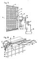
- the drawings illustrate an implement carrier 1 in the form of a tractor 1 with a conventional loading assembly 2 which is adapted to be coupled to a rotary bucket 3 of grid structure designed for the separation of fine and coarse constituents 4 and 5, respectively, of sizable materials or products 6.
- sizable material or product 6 topsoil mingled with stones and roots.
- the purpose of the sizing is to separate the topsoil, i.e. the fine constituents, from the stones and roots, i.e. the coarse constituents.
- the bucket 3 has a preferably closed back 7 and an open front 8. Adjacent the back 7 the bucket 3 has a separating part 9 which in this case is quadrilateral and whose sides 10, 11, 12 and 13 have apertures 14 therein to allow the topsoil 4, but not the stones and roots 5, to pass therethrough.
- the bucket 3 has a holder 15 with coupling means, and a rotation assembly 17.
- the coupling means 16 are adapted to permit coupling the bucket 3 to the loading assembly 2 while the rotation assembly 17 is adapted to rotate the bucket 3 in relation to the loading assembly 2 about an axis of rotation R which extends centrally through the bucket 3 in a forward direction from the back 7 to the front 8.
- the rotation assembly 17 is centered with the axis of rotation R and drives the bucket 3 via a gear transmission 18 (not shown in detail).
- the rotation assembly 17 preferably is a so-called hydraulic motor, which is connectable to the hydraulic system 19 of the tractor via conduits 20, 21.
- FIG. 12 Another location of the rotation assembly 17 is shown in figure 12.
- the rotation assembly 17 is mounted eccentrically with respect to the axis of rotation R.
- the gear transmission 18 in this case is a gear 22 on the output shaft of the rotation assembly 17, and said gear 22 drives a toothed rim 23 fixedly mounted on the back 7 of the bucket 3.
- the sides 10-13 of the separating part 9 all are of a size and they are symmetrically arranged around the axis of rotation R. Moreover, the sides 10-13 diverge symmetrically with respect to the axis of rotation R in a forward direction, i.e. the separating part 9 widens symmetrically in a forward direction. Each side 10-13 preferably diverges at an angle X of 8-30°, preferably about 12°, in relation to the axis of rotation R (or a line 24 parallel to the axis of rotation).
- the bucket 3 has a front part 25 whose four sides 26-29 constitute forward extensions of the sides 10-13 of the separating part 9.
- the sides 26-29 of the front part 25 diverge in a lesser degree with respect to the axis of rotation R than the sides 10-13 of the separating part 9 (according to a dash and dot line 12a in figure 12) and/or extend in parallel with the axis of rotation R (the full line 12b in figure 12) and/or converge in relation to the axis of rotation R (the dash and dot line 12c in figure 12).
- the angle ⁇ between the lines 12a and 24 is for instance 5° and the angle ⁇ 1 between the lines 24 and 12c is for instance also 5°.
- all sides 26-29 of the front part 25 are symmetrically arranged in relation to the axis of rotation and they are of a size, similar and extend at the same angle to the axis of rotation R.
- the sides 26-29 of the front part 25 may be different, one or more of these sides may extend at another angle to the axis of rotation R than the other side or sides 26-29, and the sides 26-29 may possibly have different shapes.
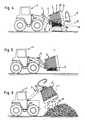
- the loading assembly 2 can be set to keep the bucket 3 in a position in which the portion 9a of the sides 10-13 of the separating part 9, which is momentarily lowermost during rotation, extends as seen from the side horizontally (along the horizontal line H in figure 4) or approximately horisontally, while the portion 25a of the sides 26-29 of the front part 25, which is momentarily lowermost during rotation, extends as seen from the side in an upward direction (along the obliquely upwardly extending line U).
- the sizable materials 6 in the bucket 3 will rest during rotation on a lower portion 25a of the bucket 3 that extends horizontally, which implies that the sizable materials 6 in the bucket 3 will be distributed over the entire length of the separating part 9 instead of collecting on part of the length of the separating part 9, as was the case earlier.
- the lowermost portion 25a of the front part 25 while rotating is simultaneously upwardly directed such that said lowermost part forms a threshold ahead of the separating part 9, said threshold preventing the sizable materials 6 from falling out through the open front 8 of the bucket 3 when the bucket 3 is rotated for separation of the topsoil 4.
- topsoil 4 will effectively be caused to pass through the apertures 14 in the separating part 9 and the topsoil 4 will be distributed uniformly over an area which is as long as the separating part 9. If the tractor besides is propelled during the separating operation a uniform topsoil layer can be spread over a large soil surface.
- the inside 30 of the bucket 3 consists of four triangular parts 30a-30d which together form a pyramidal inner part of the bucket.
- the parts 30a-30d open into central parts 32 of the inside 30 and said central parts may be polygonal or circular, as shown in the drawings.
- the inside 30 has this pyramidal shape, i.e.
- Each triangular part 30a-30d preferably extends at an angle ⁇ of 5-15°, preferably about 10°, to a line 33 at right angles to the axis of rotation R, but the parts 30a-30d may extend at other angles to said line 33.
- the bucket 3 comprises four corner profile members 34-37 extending in a forward direction from the back 7, which members are symmetrically arranged in relation to the axis of rotation R.
- the corner profile members 34-37 are welded to a four-sided frame constituting the front part 25 of the bucket 3.
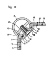
- Each corner profile member 34-37 as seen in cross section comprises an approximately semicircular central part 38, an open side 39 of which is turned inwardly, facing the interior of the bucket 3.
- the central part 38 merges in a first outer portion 40 and on an opposite side merges in a second outer portion 41; said outer portions make a right or approximately right angle with one another.
- a fixation profile member 42 which over its length has a number of threaded holes 43 for bolts 44.
- each grid unit 45-48 is of identical size and shape, and each such unit comprises a frame composed of four frame profile members 49-53 of which the two opposed frame profile members 51 and 52 are adapted to be fixed to the corner profile members 34-37, while the frame profile member 49 is adapted to be placed adjacent the back 7 and the frame profile member 50 adjacent the front part 25.
- Each grid unit 45-48 further comprises a wire grid 54 consisting of metal wires 55 which alternately pass over and below each other to form square apertures 14 or apertures of any other suitable shape, through which the topsoil 4 but not stones, roots and other coarse constituents 5 can pass.
- the metal wires 55 are suitably fixed to the frame profile members 49-53, for instance in that they are passed into slots in said profile members and then welded thereto.
- the two frame profile members 51, 52 are provided with laterally directed beads 57.
- An elongated anchorage profile member 59 with a plurality of holes 60 for bolts 44 is provided at one inner side with two recesses 61, 62 in which the beads 57 of two grid units 45-48 are adapted to engage.
- the grid units 45-48 and the corner profile members 34-37 are assembled simply by placing the frame profile members 51 or 52 of two grid units 45-48 adjacent the fixation profile member 42 of the frame profile members, by arranging the anchorage profile member 59 such that the beads 57 engage in its recesses 61, 62 and by securing the anchorage profile member 59 to the fixation profile member 42 in that the bolts 44 are screwed into the holes 43. If the grid units 45-48 have to be exchanged for some reason or other they can be dismounted simply by loosening the bolts 44 and removing the anchorage profile members 59. In this way, damaged grid units 45-48 can easily be exchanged, or grid units with one mesh size can rapidly be replaced by grid units with another mesh size.
- the grid units 45-48 may be clamped to the corner profile members 34-37 by means of the bolts 44 or they may be arranged for restricted mobility to permit "shaking off" constituents that have stuck to the metal wires 55.
- the grid units 45-48 are fastened in that the anchorage profile member 59 clamps the frame profile members 51 or 52 to the outer portions 40, 41.
- the grid units 45-48 may, however, be arranged for restricted motion simply in that a washer (not shown) is placed between the anchorage profile member 59 and the fixation profile member 42.
- Said washer should be so thick that there is formed a gap between the anchorage profile member 59 and the outer portions 40 and 41 which is wider than the frame profile members 51 or 52, whereby said members are able to move back and forth until the bead 57 bears against the anchorage profile member 59 and the fixation profile member 42, respectively.
- the front part 25 of the bucket 3 has a four-sided frame and each frame front side 26-29 consists, adjacent the separating part 9, of a reinforcing profile member 64 having an inwardly directed reinforcing point 65 which to a certain extent also forms a threshold which prevents materials 6 in the separating part 9 falling forwards.
- a reinforcing profile member 64 having an inwardly directed reinforcing point 65 which to a certain extent also forms a threshold which prevents materials 6 in the separating part 9 falling forwards.
- planar, forwardly directed edge elements 66 whose front edges 67 constitute cutting edges serving to facilitate the penetration of the bucket 3 into the materials or products 6 upon their collection.
- One, two or three, but not all the sides 10-13 off the separating part 9 may be closed entirely or for the most part. This will make it possible to transport sizable materials or products 6 in the bucket without any risk of their falling out of it.
- the bucket 3 is set so that its closed side will form the underside of the bucket 3, whereupon the bucket 3 is moved into the materials or products 6. After collection, they are transported to the contemplated location without the bucket 3 being rotated.
- the bucket 3 For collection of the unsized topsoil 6 the bucket 3 is lowered until one side 26 of the front part 25 is close to the soil surface 68, extending parallel to it. Then the tractor 1 is driven towards the topsoil pile, whereby the bucket 3 is subjected to shifting movements F, thereby digging into said topsoil pile (figure 11). The bucket 3 is then subjected to a lifting movement L and also to a tilting movement until it slants upwardly, whereupon the bucket is caused to rotate some revolutions to cause large roots and the like lying in the front part 25 of the bucket 3, to fall out (figure 2).
- the invention is not restricted to the embodiment described above and illustrated in the drawings, but can be varied within the scope of the appendant claims.
- the length of the separating part in relation to the overall length of the bucket may be smaller than that illustrated even though the separating part in general should be as long as possible.
- the separating part need not have detachable sides and/or detachable grids; these may be fixedly mounted.
- the separating part may have a number of sides other than four, for instance three sides, five sides, six sides etc., or the separating part may be circular, semicircular or shaped as a segment of a circle. Besides, these various shapes may also apply to the bucket in its entirety.
- the inside of the back of the bucket may have a shape other than pyramidal even though such a pyramidal shape is of special advantage. It is essential that the inside constitutes sections and/or edges that break up the inside in such a manner that it is not fully uniform, as seen in a direction around the axis of rotation.
- the sides of the front part need not extend symmetrically in relation to the axis of rotation and they need not be uniform as in the embodiment described but may differ with regard to shape and size. All of these sides need not either extend in parallell with or at the same angle to the axis of rotation, but one side may extend in parallel with or at a certain angle to the axis of rotation, while one or more of the other sides extend at another angle to the axis of rotation. It is not either necessary for all of these sides to form cutting edges, but it is fundamentally sufficient if one side forms such an edge.
- the rotation assembly may be of a type other than that illustrated, it may be placed in another manner and it may rotate the bucket via a device other than that illustrated.
- the rotation assembly may be an electric motor which is connectable to an electric system in the vehicle.
- the implement carriers may be of a suitable type other than those mentioned above, provided that it has the capability to lift, tilt and rotate the bucket.
- the bucket may be utilized for sizing sizable materials or products other than topsoil.
- sizable materials or products other than topsoil As an example of such other products, mention may be made of stone material comprising small and large stones to be separated.
- the separating part may comprise a rear portion closest to the back of the bucket and a fore portion closest to the front part, whereby said portions diverge at different angles relative to the axis of rotation.
- the front portion extends parallel with the sides of the front part, i.e. diverge in a lesser degree than the rear portion relative to the axis of rotation, extends parallel with the axis of rotation or converge relative to the axis of rotation.
Landscapes
- Engineering & Computer Science (AREA)
- Mining & Mineral Resources (AREA)
- Civil Engineering (AREA)
- General Engineering & Computer Science (AREA)
- Structural Engineering (AREA)
- Mechanical Engineering (AREA)
- Combined Means For Separation Of Solids (AREA)
- Shovels (AREA)
- Processing And Handling Of Plastics And Other Materials For Molding In General (AREA)
- Farming Of Fish And Shellfish (AREA)
Priority Applications (1)
| Application Number | Priority Date | Filing Date | Title |
|---|---|---|---|
| AT87106349T ATE65097T1 (de) | 1987-03-30 | 1987-05-02 | Gitterfoermige drehschaufel zum trennen von teilchen verschiedener groesse. |
Applications Claiming Priority (2)
| Application Number | Priority Date | Filing Date | Title |
|---|---|---|---|
| SE8701311A SE454711B (sv) | 1987-03-30 | 1987-03-30 | Roterbar separationskorg med kopplingsorgan till redskapsberare |
| SE8701311 | 1987-03-30 |
Publications (2)
| Publication Number | Publication Date |
|---|---|
| EP0284643A1 true EP0284643A1 (fr) | 1988-10-05 |
| EP0284643B1 EP0284643B1 (fr) | 1991-07-10 |
Family
ID=20368035
Family Applications (1)
| Application Number | Title | Priority Date | Filing Date |
|---|---|---|---|
| EP87106349A Expired - Lifetime EP0284643B1 (fr) | 1987-03-30 | 1987-05-02 | Godet rotatif grillagé pour la séparation en fonction de leur grosseur des particules d'un matériau |
Country Status (5)
| Country | Link |
|---|---|
| US (1) | US5002656A (fr) |
| EP (1) | EP0284643B1 (fr) |
| AT (1) | ATE65097T1 (fr) |
| DE (1) | DE3771325D1 (fr) |
| SE (1) | SE454711B (fr) |
Cited By (10)
| Publication number | Priority date | Publication date | Assignee | Title |
|---|---|---|---|---|
| WO1990012929A1 (fr) * | 1989-04-21 | 1990-11-01 | Tord Jonsson | Systeme pour une pelle mecanique trieuse |
| GB2235141A (en) * | 1989-08-23 | 1991-02-27 | Darryl Thorpe | Riddle |
| DE4007409A1 (de) * | 1990-03-06 | 1991-09-12 | Gerhard Huebner | Verfahren zum entfernen von fremdkoerpern aus boeden und vorrichtung zur durchfuehrung des verfahrens |
| EP1177839A1 (fr) * | 2000-07-26 | 2002-02-06 | Luca Vaccaro | Godet de criblage et de mélange |
| WO2003068419A1 (fr) * | 2002-02-12 | 2003-08-21 | Extec Screens And Crushers Limited | Installation de criblage |
| ITPD20100221A1 (it) * | 2010-07-15 | 2012-01-16 | Meccanica Breganzese S P A | Benna vagliatrice |
| ITUB20159565A1 (it) * | 2015-12-14 | 2017-06-14 | Mecc Breganzese S P A | Cesto vagliatore e benna comprendente lo stesso |
| EP3339515A1 (fr) | 2016-12-23 | 2018-06-27 | Javier Aracama Martinez De Lahidalga | Godet et procédé de tamisage d'un matériau inerte |
| SE1950913A1 (sv) * | 2019-08-05 | 2021-02-06 | Bo Johansson | Stensorterarskopa och metod för dess användning |
| WO2021094654A1 (fr) * | 2019-11-14 | 2021-05-20 | Huvilaveistämö A. Suojala | Dispositif de criblage |
Families Citing this family (16)
| Publication number | Priority date | Publication date | Assignee | Title |
|---|---|---|---|---|
| US5311684A (en) * | 1990-05-04 | 1994-05-17 | Rudolf Van Dalfsen | Scooping apparatus, vehicle and coupling plate therefore |
| CA2074052C (fr) * | 1992-07-16 | 1998-05-05 | Real R. Laprade | Dispositif de tamisage de sol |
| US5301813A (en) * | 1992-11-16 | 1994-04-12 | Schnittjer Bradley J | Apparatus for separating material |
| SE501521C2 (sv) * | 1994-04-20 | 1995-03-06 | Gunborg Margit Linnea Hellgren | Skopa med sållningsanordning |
| US5732827A (en) * | 1995-03-03 | 1998-03-31 | Portec Inc. | Screening apparatus |
| US6439393B1 (en) * | 2000-02-14 | 2002-08-27 | Bruce K. Zeller | Method and apparatus for separating excavated material |
| AUPS270802A0 (en) * | 2002-05-31 | 2002-06-20 | Turnbull, Sam Dominic Seaton | A screen/mixer |
| US8534371B2 (en) * | 2009-08-13 | 2013-09-17 | Kent Roessler | Rock picker and tumbler |
| US20110100882A1 (en) * | 2009-10-30 | 2011-05-05 | Beam Roger D | Portable solids screening bucket |
| KR101366423B1 (ko) | 2011-11-16 | 2014-02-24 | 상진옥 | 회전식 스크린 버켓 |
| FI124431B (fi) * | 2013-02-01 | 2014-08-29 | Pohmako Ky | Tärytinlaite, kauha ja menetelmä tärytykseen |
| US20190168232A1 (en) * | 2016-11-21 | 2019-06-06 | Thomas Joseph Bruggemann | Multi-Purpose Plant Flower Trimmer and Separator |
| US20170197217A1 (en) * | 2016-11-21 | 2017-07-13 | Thomas Bruggemann | Dual Purpose Female Cannabis Seedless Flower Bud Trimmers, Kief Separators and Methods |
| IT201700078145A1 (it) * | 2017-07-11 | 2019-01-11 | Mecc Breganzese S P A In Breve Mb S P A | Benna vagliatrice |
| US10974280B2 (en) * | 2017-09-27 | 2021-04-13 | Theodore Leonard Kasper | Rock separator |
| US20220002967A1 (en) * | 2020-07-06 | 2022-01-06 | Thomas Sampson | Dirt Screening Bucket Attachment Device |
Citations (6)
| Publication number | Priority date | Publication date | Assignee | Title |
|---|---|---|---|---|
| FR1486732A (fr) * | 1966-07-13 | 1967-06-30 | Appareil à l'usage des travaux de terrassem ents, de bâtiments ou similaires, les machines munies de cet outil ou similaire | |
| US3765490A (en) * | 1972-06-29 | 1973-10-16 | G Logue | Combined loader bucket and fines separator |
| US4005755A (en) * | 1973-12-14 | 1977-02-01 | Bakke Even A | Machine for rock removal and soil cultivation |
| US4157956A (en) * | 1978-04-19 | 1979-06-12 | Robinson Leo E | Screening bucket |
| FR2540905A1 (fr) * | 1983-02-14 | 1984-08-17 | Ardennes Equip | Perfectionnements aux godets a crible pour chargeur frontal |
| EP0178656A1 (fr) * | 1984-10-18 | 1986-04-23 | Prodec Inter Ab | Procédé et dispositif pour la séparation des produits gros et fins d'excavation |
Family Cites Families (24)
| Publication number | Priority date | Publication date | Assignee | Title |
|---|---|---|---|---|
| US338847A (en) * | 1886-03-30 | Stephen b | ||
| US248242A (en) * | 1881-10-11 | Rotary bolt | ||
| US683775A (en) * | 1900-12-15 | 1901-10-01 | Millard F Kirkpatrick | Dipper for steam-shovels. |
| US928965A (en) * | 1908-06-01 | 1909-07-27 | Hanna Engineering Works | Revolving sifting-screen. |
| US1793389A (en) * | 1928-07-07 | 1931-02-17 | Elmer William | Ballast-cleaning apparatus |
| US2119676A (en) * | 1934-05-28 | 1938-06-07 | Richard D Heller | Trommel |
| DE767207C (de) * | 1938-10-12 | 1952-02-28 | Heinrich Lanz Ag | Sortiertrommel fuer Dreschmaschinen |
| US2422985A (en) * | 1944-07-04 | 1947-06-24 | Laurence L Reckler | Earth handling implement |
| US2882976A (en) * | 1955-11-07 | 1959-04-21 | John H Wheeler | Machine for harvesting crops |
| US3033394A (en) * | 1959-06-29 | 1962-05-08 | Kash Products Inc | Multipurpose apparatus for earthworking and the like |
| US3072257A (en) * | 1959-08-21 | 1963-01-08 | Lester W Hockenberry | Combined gravel collecting and screening mechanism |
| US3003265A (en) * | 1959-12-30 | 1961-10-10 | Lutjens Herman | Bucket device |
| US3231246A (en) * | 1964-03-13 | 1966-01-25 | American Equipment Co | Mixing apparatus for attachment to tractors |
| US3208593A (en) * | 1964-04-27 | 1965-09-28 | Dietert Co Harry W | Cylindrical screening apparatus |
| US3431662A (en) * | 1966-01-28 | 1969-03-11 | Marcus J Bles | Snow removing basket for tractor |
| US3461968A (en) * | 1966-04-28 | 1969-08-19 | Rca Corp | Screening loader |
| GB1291555A (en) * | 1970-01-15 | 1972-10-04 | Econofuel Ltd | Apparatus for and method of screening free running material |
| GB1512206A (en) * | 1974-12-21 | 1978-05-24 | Foulger Ltd W | Cleaning and loading apparatus for root crops |
| US4018675A (en) * | 1975-05-19 | 1977-04-19 | Petrucci Ben G | Waste sorting machine |
| NO800181L (no) * | 1980-01-25 | 1981-08-13 | Herbjoern Loekken | Anordning ved gravemaskin. |
| SE440522B (sv) * | 1980-09-15 | 1985-08-05 | Rolf Mannbro | Anordning vid grevskopor med en drivanordning for att kunna vrida skopan i obegrensad vinkel der drivanordningen er forsedd med en bromsanordning |
| DE3101606A1 (de) * | 1981-01-20 | 1982-08-19 | Raiffeisenbank Winzer-Hengersberg eG, 8351 Winzer | Vorrichtung zum laden von druckempfindlichem gut voneiner halde, insbesondere von zuckenrueben auf ein transportfahrzeug zum abtransport vom feld |
| JPS5810955A (ja) * | 1981-07-10 | 1983-01-21 | Canon Inc | 画像形成装置 |
| AT383511B (de) * | 1983-02-17 | 1987-07-10 | Voest Alpine Ag | Siebvorrichtung |
-
1987
- 1987-03-30 SE SE8701311A patent/SE454711B/sv not_active IP Right Cessation
- 1987-05-02 EP EP87106349A patent/EP0284643B1/fr not_active Expired - Lifetime
- 1987-05-02 AT AT87106349T patent/ATE65097T1/de active
- 1987-05-02 DE DE8787106349T patent/DE3771325D1/de not_active Expired - Fee Related
-
1988
- 1988-03-25 US US07/173,551 patent/US5002656A/en not_active Expired - Fee Related
Patent Citations (6)
| Publication number | Priority date | Publication date | Assignee | Title |
|---|---|---|---|---|
| FR1486732A (fr) * | 1966-07-13 | 1967-06-30 | Appareil à l'usage des travaux de terrassem ents, de bâtiments ou similaires, les machines munies de cet outil ou similaire | |
| US3765490A (en) * | 1972-06-29 | 1973-10-16 | G Logue | Combined loader bucket and fines separator |
| US4005755A (en) * | 1973-12-14 | 1977-02-01 | Bakke Even A | Machine for rock removal and soil cultivation |
| US4157956A (en) * | 1978-04-19 | 1979-06-12 | Robinson Leo E | Screening bucket |
| FR2540905A1 (fr) * | 1983-02-14 | 1984-08-17 | Ardennes Equip | Perfectionnements aux godets a crible pour chargeur frontal |
| EP0178656A1 (fr) * | 1984-10-18 | 1986-04-23 | Prodec Inter Ab | Procédé et dispositif pour la séparation des produits gros et fins d'excavation |
Cited By (14)
| Publication number | Priority date | Publication date | Assignee | Title |
|---|---|---|---|---|
| WO1990012929A1 (fr) * | 1989-04-21 | 1990-11-01 | Tord Jonsson | Systeme pour une pelle mecanique trieuse |
| GB2235141A (en) * | 1989-08-23 | 1991-02-27 | Darryl Thorpe | Riddle |
| DE4007409A1 (de) * | 1990-03-06 | 1991-09-12 | Gerhard Huebner | Verfahren zum entfernen von fremdkoerpern aus boeden und vorrichtung zur durchfuehrung des verfahrens |
| EP1177839A1 (fr) * | 2000-07-26 | 2002-02-06 | Luca Vaccaro | Godet de criblage et de mélange |
| WO2003068419A1 (fr) * | 2002-02-12 | 2003-08-21 | Extec Screens And Crushers Limited | Installation de criblage |
| US7374049B2 (en) | 2002-02-12 | 2008-05-20 | Extec Screens & Crushers Limited | Screening plant |
| ITPD20100221A1 (it) * | 2010-07-15 | 2012-01-16 | Meccanica Breganzese S P A | Benna vagliatrice |
| WO2012007921A1 (fr) | 2010-07-15 | 2012-01-19 | Meccanica Breganzese S.P.A. In Breve Mb S.P.A. | Godet de criblage pour machine de travaux |
| US8678195B2 (en) | 2010-07-15 | 2014-03-25 | Meccanica Breganzese S.P.A. In Breve Mb S.P.A. | Screening bucket |
| ITUB20159565A1 (it) * | 2015-12-14 | 2017-06-14 | Mecc Breganzese S P A | Cesto vagliatore e benna comprendente lo stesso |
| EP3339515A1 (fr) | 2016-12-23 | 2018-06-27 | Javier Aracama Martinez De Lahidalga | Godet et procédé de tamisage d'un matériau inerte |
| SE1950913A1 (sv) * | 2019-08-05 | 2021-02-06 | Bo Johansson | Stensorterarskopa och metod för dess användning |
| SE543599C2 (sv) * | 2019-08-05 | 2021-04-13 | Bo Johansson | Stensorterarskopa och metod för dess användning |
| WO2021094654A1 (fr) * | 2019-11-14 | 2021-05-20 | Huvilaveistämö A. Suojala | Dispositif de criblage |
Also Published As
| Publication number | Publication date |
|---|---|
| ATE65097T1 (de) | 1991-07-15 |
| DE3771325D1 (de) | 1991-08-14 |
| SE454711B (sv) | 1988-05-24 |
| EP0284643B1 (fr) | 1991-07-10 |
| SE8701311D0 (sv) | 1987-03-30 |
| US5002656A (en) | 1991-03-26 |
Similar Documents
| Publication | Publication Date | Title |
|---|---|---|
| EP0284643B1 (fr) | Godet rotatif grillagé pour la séparation en fonction de leur grosseur des particules d'un matériau | |
| EP0178656B1 (fr) | Procédé et dispositif pour la séparation des produits gros et fins d'excavation | |
| EP0387794B1 (fr) | Véhicule automoteur utilitaire pour le nettoyage des plages | |
| US8893409B1 (en) | Excavating machinery with bucket for screening and/or mixing excavated material | |
| KR100871106B1 (ko) | 구근작물 수확기 | |
| US7066275B1 (en) | Rock separator with beveled tines and removable grates | |
| US4988005A (en) | Sifter | |
| US20150259876A1 (en) | Topsoil Separator and Spreader for Skid Steer Loaders | |
| US7117951B2 (en) | Landscape preparation apparatus | |
| KR102336088B1 (ko) | 트랙터 장착용 구근 작물 수확 장치 | |
| CA2396288C (fr) | Installation de criblage du sol | |
| JPH01190807A (ja) | 砂浜清掃装置 | |
| US3596717A (en) | Beach-cleaning vehicle | |
| KR102051404B1 (ko) | 구근류 채굴장치 | |
| US4698925A (en) | Soil reclaiming implement | |
| US7013982B2 (en) | Range-master vehicle for safe recovery of ordnance and land mines | |
| JPH07107829A (ja) | 収穫機 | |
| US7055698B1 (en) | Rock separator | |
| US6625908B1 (en) | Apparatus for digging a trench | |
| GB2252575A (en) | Separating device for fishing dredge | |
| US8555530B2 (en) | System and method for pipeline padding | |
| EP4001508A1 (fr) | Dispositif et procédé de nettoyage du sable | |
| EP1077289A2 (fr) | Dispositif pour travailler le sol | |
| DE8123263U1 (de) | "an eine fahrbare arbeitsmaschine anbaubare einrichtung zur aufbereitung von rohen erdboeden" | |
| DE102022100698A1 (de) | Vorrichtung zur Sandreinigung |
Legal Events
| Date | Code | Title | Description |
|---|---|---|---|
| PUAI | Public reference made under article 153(3) epc to a published international application that has entered the european phase |
Free format text: ORIGINAL CODE: 0009012 |
|
| AK | Designated contracting states |
Kind code of ref document: A1 Designated state(s): AT BE CH DE ES FR GB GR IT LI LU NL SE |
|
| 17P | Request for examination filed |
Effective date: 19881226 |
|
| 17Q | First examination report despatched |
Effective date: 19901016 |
|
| GRAA | (expected) grant |
Free format text: ORIGINAL CODE: 0009210 |
|
| ITF | It: translation for a ep patent filed | ||
| AK | Designated contracting states |
Kind code of ref document: B1 Designated state(s): AT BE CH DE ES FR GB GR IT LI LU NL SE |
|
| PG25 | Lapsed in a contracting state [announced via postgrant information from national office to epo] |
Ref country code: SE Effective date: 19910710 Ref country code: LI Effective date: 19910710 Ref country code: GR Free format text: LAPSE BECAUSE OF FAILURE TO SUBMIT A TRANSLATION OF THE DESCRIPTION OR TO PAY THE FEE WITHIN THE PRESCRIBED TIME-LIMIT Effective date: 19910710 Ref country code: CH Effective date: 19910710 Ref country code: BE Effective date: 19910710 Ref country code: AT Effective date: 19910710 |
|
| REF | Corresponds to: |
Ref document number: 65097 Country of ref document: AT Date of ref document: 19910715 Kind code of ref document: T |
|
| ET | Fr: translation filed | ||
| REF | Corresponds to: |
Ref document number: 3771325 Country of ref document: DE Date of ref document: 19910814 |
|
| REG | Reference to a national code |
Ref country code: CH Ref legal event code: PL |
|
| PG25 | Lapsed in a contracting state [announced via postgrant information from national office to epo] |
Ref country code: ES Free format text: LAPSE BECAUSE OF FAILURE TO SUBMIT A TRANSLATION OF THE DESCRIPTION OR TO PAY THE FEE WITHIN THE PRESCRIBED TIME-LIMIT Effective date: 19911021 |
|
| PLBE | No opposition filed within time limit |
Free format text: ORIGINAL CODE: 0009261 |
|
| STAA | Information on the status of an ep patent application or granted ep patent |
Free format text: STATUS: NO OPPOSITION FILED WITHIN TIME LIMIT |
|
| PG25 | Lapsed in a contracting state [announced via postgrant information from national office to epo] |
Ref country code: LU Free format text: LAPSE BECAUSE OF NON-PAYMENT OF DUE FEES Effective date: 19920531 |
|
| 26N | No opposition filed | ||
| PGFP | Annual fee paid to national office [announced via postgrant information from national office to epo] |
Ref country code: FR Payment date: 20010405 Year of fee payment: 15 |
|
| PGFP | Annual fee paid to national office [announced via postgrant information from national office to epo] |
Ref country code: GB Payment date: 20010427 Year of fee payment: 15 |
|
| PGFP | Annual fee paid to national office [announced via postgrant information from national office to epo] |
Ref country code: NL Payment date: 20010509 Year of fee payment: 15 |
|
| PGFP | Annual fee paid to national office [announced via postgrant information from national office to epo] |
Ref country code: DE Payment date: 20010621 Year of fee payment: 15 |
|
| REG | Reference to a national code |
Ref country code: GB Ref legal event code: IF02 |
|
| PG25 | Lapsed in a contracting state [announced via postgrant information from national office to epo] |
Ref country code: GB Free format text: LAPSE BECAUSE OF NON-PAYMENT OF DUE FEES Effective date: 20020502 |
|
| PG25 | Lapsed in a contracting state [announced via postgrant information from national office to epo] |
Ref country code: NL Free format text: LAPSE BECAUSE OF NON-PAYMENT OF DUE FEES Effective date: 20021201 |
|
| PG25 | Lapsed in a contracting state [announced via postgrant information from national office to epo] |
Ref country code: DE Free format text: LAPSE BECAUSE OF NON-PAYMENT OF DUE FEES Effective date: 20021203 |
|
| GBPC | Gb: european patent ceased through non-payment of renewal fee |
Effective date: 20020502 |
|
| PG25 | Lapsed in a contracting state [announced via postgrant information from national office to epo] |
Ref country code: FR Free format text: LAPSE BECAUSE OF NON-PAYMENT OF DUE FEES Effective date: 20030131 |
|
| NLV4 | Nl: lapsed or anulled due to non-payment of the annual fee |
Effective date: 20021201 |
|
| REG | Reference to a national code |
Ref country code: FR Ref legal event code: ST |
|
| PG25 | Lapsed in a contracting state [announced via postgrant information from national office to epo] |
Ref country code: IT Free format text: LAPSE BECAUSE OF NON-PAYMENT OF DUE FEES;WARNING: LAPSES OF ITALIAN PATENTS WITH EFFECTIVE DATE BEFORE 2007 MAY HAVE OCCURRED AT ANY TIME BEFORE 2007. THE CORRECT EFFECTIVE DATE MAY BE DIFFERENT FROM THE ONE RECORDED. Effective date: 20050502 |