EP0284675A1 - Séparateur vapeur-eau en tandem - Google Patents
Séparateur vapeur-eau en tandem Download PDFInfo
- Publication number
- EP0284675A1 EP0284675A1 EP87302743A EP87302743A EP0284675A1 EP 0284675 A1 EP0284675 A1 EP 0284675A1 EP 87302743 A EP87302743 A EP 87302743A EP 87302743 A EP87302743 A EP 87302743A EP 0284675 A1 EP0284675 A1 EP 0284675A1
- Authority
- EP
- European Patent Office
- Prior art keywords
- riser
- water
- mixture
- shell
- separator according
- Prior art date
- Legal status (The legal status is an assumption and is not a legal conclusion. Google has not performed a legal analysis and makes no representation as to the accuracy of the status listed.)
- Granted
Links
- XLYOFNOQVPJJNP-UHFFFAOYSA-N water Substances O XLYOFNOQVPJJNP-UHFFFAOYSA-N 0.000 title claims abstract description 72
- 239000000203 mixture Substances 0.000 claims abstract description 42
- 238000000926 separation method Methods 0.000 claims abstract description 10
- 238000005192 partition Methods 0.000 claims abstract 3
- 230000000630 rising effect Effects 0.000 claims description 9
- 238000007599 discharging Methods 0.000 claims description 8
- 230000000875 corresponding effect Effects 0.000 claims 1
- 230000004087 circulation Effects 0.000 description 4
- 238000012986 modification Methods 0.000 description 4
- 230000004048 modification Effects 0.000 description 4
- 239000007788 liquid Substances 0.000 description 2
- 230000004323 axial length Effects 0.000 description 1
- 239000012530 fluid Substances 0.000 description 1
- 230000005484 gravity Effects 0.000 description 1
Images


Classifications
-
- F—MECHANICAL ENGINEERING; LIGHTING; HEATING; WEAPONS; BLASTING
- F22—STEAM GENERATION
- F22B—METHODS OF STEAM GENERATION; STEAM BOILERS
- F22B37/00—Component parts or details of steam boilers
- F22B37/02—Component parts or details of steam boilers applicable to more than one kind or type of steam boiler
- F22B37/26—Steam-separating arrangements
- F22B37/32—Steam-separating arrangements using centrifugal force
-
- B—PERFORMING OPERATIONS; TRANSPORTING
- B04—CENTRIFUGAL APPARATUS OR MACHINES FOR CARRYING-OUT PHYSICAL OR CHEMICAL PROCESSES
- B04C—APPARATUS USING FREE VORTEX FLOW, e.g. CYCLONES
- B04C3/00—Apparatus in which the axial direction of the vortex flow following a screw-thread type line remains unchanged ; Devices in which one of the two discharge ducts returns centrally through the vortex chamber, a reverse-flow vortex being prevented by bulkheads in the central discharge duct
- B04C3/04—Multiple arrangement thereof
-
- B—PERFORMING OPERATIONS; TRANSPORTING
- B04—CENTRIFUGAL APPARATUS OR MACHINES FOR CARRYING-OUT PHYSICAL OR CHEMICAL PROCESSES
- B04C—APPARATUS USING FREE VORTEX FLOW, e.g. CYCLONES
- B04C5/00—Apparatus in which the axial direction of the vortex is reversed
- B04C5/24—Multiple arrangement thereof
- B04C5/26—Multiple arrangement thereof for series flow
Definitions
- This invention relates to a steam processing apparatus and, more particularly, to a separator for receiving a mixture of steam and water, separating the steam from the water in two stages and discharging the steam and the water from separate outlets.
- the steam-water separator of the present invention comprises a first stage riser adapted to receive a steam-water mixture, baffle means disposed in a spaced relation to said riser, at least one discharge slot formed through said riser, a discharge member for the or each slot registering therewith for receiving said mixture and discharging it against said baffle means to promote the separation of water from said mixture, said water collecting on said baffle means and said mixture rising by buoyant forces, a second stage riser disposed above said first stage riser, means for directing said rising mixture into said second stage riser, additional baffle means disposed in a spaced relation to said second stage riser, at least one discharge slot formed through said second stage riser, and a discharge member for the or each latter slot in registration therewith for receiving said rising mixture and discharging it against said baffle means to facilitate additional separation of water from said mixture, said water collecting on said additional baffle means and said mixture rising by buoyant forces for further treatment.
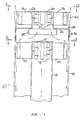
- the reference numeral 10 refers in general to the steam-water separator of the present invention.
- the separator 10 includes a first stage riser 12, which is adapted to receive a steam-water mixture from a riser or tube (not shown) or from a steam drum (not shown) which can be a part of a natural circulation steam generator, or the like.
- the riser 12 extends within an upright cylindrical shell 14 in a coaxially spaced relationship.
- a top plate 16 extends over the upper end of the riser 12 and a plurality of slots 18 are formed through the upper wall portion of the riser.
- a plurality of arcuate arms 20 are connected to the riser 12 in registry with the slots 18, respectively, with the free ends of the arms being open to permit the steam-water mixture to discharge therefrom in a substantially tangential direction relative to the inner wall of the shell 14. It is understood that a support structure (not shown) can be provided within the shell 14 for supporting the riser 12 within the shell in the coaxial position shown.
- a second stage riser 24 is provided in the upper portion of the shell 14 in a spaced relation to the riser 12.
- the riser 24 is supported relative to the shell 14 by a horizontally extending splash ring 26 having a drip ring 28 extending downwardly from the lower portion thereof and adapted to receive the mixture rising in the shell from the first stage separator formed by the riser 12 and the arms 20.
- a top plate 30 extends over the upper end of the riser 24 and a plurality of slots 32 are formed through the riser.
- a plurality of arcuate arms 34 are connected to, and extend outwardly from, the riser 24 in registry with the slots 32. The free ends of the arms 34 are open to permit the steam-water mixture to discharge therefrom in a substantially tangential direction relative to the inner wall of the shell 14.
- a plurality of water relief holes 36 extend through a portion of the shell 14 between the arms 20 and the splash ring 26.
- a series of drain openings 38 are provided around the shell 14 immediately above the splash ring 26.
- a series of spaced discharge slots 40 are provided in the upper end portion of the shell 14.
- the mixture of steam and water entering the lowers end portion of the riser 12 rises upwardly and then passes radially outwardly from the riser through the slots 18 and into arcuate arms 20 where it is directed tangentially against the inner wall of the shell 14.
- the water portion of the mixture collects on the inner wall of the shell 14 and a portion of this water flows down the wall by gravitational forces and is collected in the steam drum or in any other known manner.
- the remaining portion of the water collecting on the inner wall of the shell 14 rises upwardly slightly along the inner surface of the shell above the tops of the arms 20 due to the kinetic energy in the jet streams of the steam-water mixture discharging from the arms. This portion of water discharges from the water relief holes 36 and then falls by gravity downwardly into the steam drum, or the like.
- the remaining portion of the mixture rises upwardly in the shell 14 and is directed into the lower end portion of the riser 24 by the splash ring 26 and the drip ring 28.
- the mixture then passes radially outwardly from the riser 24 through the slots 32 and through the arcuate arms 34. This causes an additional separation of the steam from the water, with the steam discharging through the slots 40 whereby it leaves the separator for further treatment.
- the water portion of the mixture collects on the upper inner wall of the shell 14 and passes downwardly through the drain openings 38 where it is collected in the steam drum, or the like.
- the steam-water separator is achieved at relatively low pressure loss and low carryover over a wide range of steam and water flow conditions.
- the separator 10 can operate under high steam and water loading while maintaining the low pressure loss.
- the separator of the present invention is of a simple, efficient design and is relatively inexpensive to fabricate.
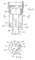
- the shell 14 is terminated a short way above the discharge member 20 in an open end and the water relief holes of the previous embodiment are omitted.
- the splash ring 26 extends radially to a depending skirt 42 which surrounds the top end of the shell 14.
- a further cylindrical member 44 of greater diameter than the skirt 42 surrounds the discharge member 34 and extends downwards to overlap the said skirt 42.
- Members 44 and 42 comprise shrouds which trap any water which is separated from the steam-water mixture as a consequence of its centrifugal motion when it emerges from the discharge means 20, 34.
- the swirl kinetic energy is absorbed on the inner walls of members 42, 44 and the water drops under gravitational force to the base of the steam drum.
- a plurality of radial fins or plates 46 are disposed within and at the base of the shell 14 within and at the base of the shell 14 there is disposed a plurality of radial fins or plates 46. These plates extend for a short way up the shell from the base thereof and serve to remove any swirl kinetic energy from the water which drains downwards from the inner walls of the shell and from the discharge device 20.
- the fins or plates 46 are uniformly perforated (47) to assist in the removal of the said swirl kinetic energy.
- Shell 14 has a bottom axial end wall formed by an inverted dish-shaped member 48 on which the fins 46 are mounted.
- the member 48 is also perforated over its whole surface with perforations 50 to allow drainage of water from the separator.
- Riser 12 is fitted internally along its axial length with a pair of helical ribs 52, 54. These ribs act as baffles and provide the steam-water mixture with pre-spin before it enters the first stage discharge member 20.
- the individual arms 20, 34 of the discharge members, or of at least one of the discharge members are straight along a substantial part of their length instead of being curved or spiral-shaped as in Figures 2 and 3. These arms are disposed substantially tangentially to their root diameter. The ends of the arms are curved all in the same direction so as to discharge the steam-water mixture in a direction substantially tangential to the inner wall of the shell 14 or shroud 44, as the case may be.
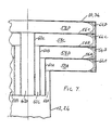
- the respective riser and discharge devices 20, 34 may also be modified as shown in Figures 7 and 8, wherein Figure 8 is a purely schematic illustration of the modified structure shown in detail in Figure 7.
- each arm of the respective discharge device is fitted with a plurality of horizontal separators 56A-56C spaced apart in the vertical direction so as to divide the hollow interior into a series of substantially equally dimensioned passages 58A-58D arranged one above the other.
- the separators 56A-56C are each joined to a respective one of a number of nested vertically disposed cylindrical coaxial separators 60A-60C mounted in the respective riser 12, 28.
- the inner coaxial separator 60C defines a cylindrical passage 62D which communicates with the top compartment in each of the arms of the discharge device 20, 34 and the other two coaxial separators 60A, 60B define annular passages 62A-62C each of which communicates with respective corresponding passages in the said arms, each passage thereby defining a path which is isolated from the paths defined by the other passages.
- the purpose of this arrangement is to assist in the efficient discharge of the separated water and steam from the respective discharge device.
- the kinetic energy contained by the separated water droplets carries the latter upwards to the upper surfaces of the discharge device.
- the water has a tendency to mainly collect at the top of the device and be discharged at a higher level than the separated steam and so become re-entrained with the steam as the latter rises.
Landscapes
- Engineering & Computer Science (AREA)
- Physics & Mathematics (AREA)
- Thermal Sciences (AREA)
- Mechanical Engineering (AREA)
- General Engineering & Computer Science (AREA)
- Separating Particles In Gases By Inertia (AREA)
- Cyclones (AREA)
Priority Applications (2)
| Application Number | Priority Date | Filing Date | Title |
|---|---|---|---|
| EP19870302743 EP0284675B1 (fr) | 1987-03-30 | 1987-03-30 | Séparateur vapeur-eau en tandem |
| DE19873783361 DE3783361T2 (de) | 1987-03-30 | 1987-03-30 | Tandemabscheider fuer ein dampf-wasser-gemisch. |
Applications Claiming Priority (1)
| Application Number | Priority Date | Filing Date | Title |
|---|---|---|---|
| EP19870302743 EP0284675B1 (fr) | 1987-03-30 | 1987-03-30 | Séparateur vapeur-eau en tandem |
Publications (2)
| Publication Number | Publication Date |
|---|---|
| EP0284675A1 true EP0284675A1 (fr) | 1988-10-05 |
| EP0284675B1 EP0284675B1 (fr) | 1992-12-30 |
Family
ID=8197840
Family Applications (1)
| Application Number | Title | Priority Date | Filing Date |
|---|---|---|---|
| EP19870302743 Expired EP0284675B1 (fr) | 1987-03-30 | 1987-03-30 | Séparateur vapeur-eau en tandem |
Country Status (2)
| Country | Link |
|---|---|
| EP (1) | EP0284675B1 (fr) |
| DE (1) | DE3783361T2 (fr) |
Cited By (8)
| Publication number | Priority date | Publication date | Assignee | Title |
|---|---|---|---|---|
| EP0728509A3 (fr) * | 1995-02-24 | 1997-05-02 | Fresenius Ag | Dispositif pour éliminer les bulles de gaz d'un liquide médical |
| EP0776686A1 (fr) * | 1995-12-01 | 1997-06-04 | Exxon Research And Engineering Company | Séparateur gaz/solides à plusieurs étappes |
| WO2007107740A1 (fr) * | 2006-03-23 | 2007-09-27 | Acis R & D Limited | Séparateur de particules |
| US7856170B2 (en) | 2005-03-15 | 2010-12-21 | Rational Ag | Device for producing steam and cooking appliance |
| CN101648093B (zh) * | 2008-08-15 | 2011-09-14 | 中冶赛迪工程技术股份有限公司 | 一种同轴式分离器 |
| US8152877B2 (en) | 2010-03-12 | 2012-04-10 | Euro-Pro Operating Llc | Shroud for a cleaning service apparatus |
| CN103933834A (zh) * | 2013-01-17 | 2014-07-23 | 陈永真 | 旋风式热空气全热回收除尘除湿汽水分离机 |
| CN115445364A (zh) * | 2022-09-26 | 2022-12-09 | 中国船舶重工集团公司第七一九研究所 | 一种汽水分离器 |
Families Citing this family (1)
| Publication number | Priority date | Publication date | Assignee | Title |
|---|---|---|---|---|
| WO2002012790A1 (fr) | 2000-08-09 | 2002-02-14 | Rational Ag | Procede et dispositif de production de vapeur, en particulier pour un appareil de cuisson |
Citations (7)
| Publication number | Priority date | Publication date | Assignee | Title |
|---|---|---|---|---|
| DE931170C (de) * | 1948-01-30 | 1955-08-01 | Comb Engineering Superheater | Fliehkraftabscheider |
| US3314220A (en) * | 1965-03-22 | 1967-04-18 | Foster Wheeler Corp | Multiannular centrifugal separator |
| DE2204829A1 (de) * | 1972-02-02 | 1973-08-09 | Siemens Ag | Fliehkraftabscheider |
| EP0018840A1 (fr) * | 1979-05-02 | 1980-11-12 | Westinghouse Electric Corporation | Appareil pour séparer d'humidité entraînée de vapeur saturée dans un genérateur de vapeur nucléaire |
| US4289514A (en) * | 1980-06-25 | 1981-09-15 | The Babcock & Wilcox Company | Stacked re-entrant arm vapor-liquid separator |
| GB2126499A (en) * | 1982-09-07 | 1984-03-28 | Foster Wheeler Energy Corp | Steam separator |
| FR2558741A1 (fr) * | 1984-01-31 | 1985-08-02 | Electricite De France | Separateur de melanges par centrifugation |
-
1987
- 1987-03-30 DE DE19873783361 patent/DE3783361T2/de not_active Expired - Fee Related
- 1987-03-30 EP EP19870302743 patent/EP0284675B1/fr not_active Expired
Patent Citations (7)
| Publication number | Priority date | Publication date | Assignee | Title |
|---|---|---|---|---|
| DE931170C (de) * | 1948-01-30 | 1955-08-01 | Comb Engineering Superheater | Fliehkraftabscheider |
| US3314220A (en) * | 1965-03-22 | 1967-04-18 | Foster Wheeler Corp | Multiannular centrifugal separator |
| DE2204829A1 (de) * | 1972-02-02 | 1973-08-09 | Siemens Ag | Fliehkraftabscheider |
| EP0018840A1 (fr) * | 1979-05-02 | 1980-11-12 | Westinghouse Electric Corporation | Appareil pour séparer d'humidité entraînée de vapeur saturée dans un genérateur de vapeur nucléaire |
| US4289514A (en) * | 1980-06-25 | 1981-09-15 | The Babcock & Wilcox Company | Stacked re-entrant arm vapor-liquid separator |
| GB2126499A (en) * | 1982-09-07 | 1984-03-28 | Foster Wheeler Energy Corp | Steam separator |
| FR2558741A1 (fr) * | 1984-01-31 | 1985-08-02 | Electricite De France | Separateur de melanges par centrifugation |
Cited By (11)
| Publication number | Priority date | Publication date | Assignee | Title |
|---|---|---|---|---|
| EP0728509A3 (fr) * | 1995-02-24 | 1997-05-02 | Fresenius Ag | Dispositif pour éliminer les bulles de gaz d'un liquide médical |
| EP0776686A1 (fr) * | 1995-12-01 | 1997-06-04 | Exxon Research And Engineering Company | Séparateur gaz/solides à plusieurs étappes |
| US7856170B2 (en) | 2005-03-15 | 2010-12-21 | Rational Ag | Device for producing steam and cooking appliance |
| WO2007107740A1 (fr) * | 2006-03-23 | 2007-09-27 | Acis R & D Limited | Séparateur de particules |
| US8097057B2 (en) | 2006-03-23 | 2012-01-17 | Euro-Pro Operating Llc | Particle separator |
| CN101648093B (zh) * | 2008-08-15 | 2011-09-14 | 中冶赛迪工程技术股份有限公司 | 一种同轴式分离器 |
| US8152877B2 (en) | 2010-03-12 | 2012-04-10 | Euro-Pro Operating Llc | Shroud for a cleaning service apparatus |
| CN103933834A (zh) * | 2013-01-17 | 2014-07-23 | 陈永真 | 旋风式热空气全热回收除尘除湿汽水分离机 |
| CN103933834B (zh) * | 2013-01-17 | 2016-05-25 | 陈永真 | 旋风式热空气全热回收除尘除湿汽水分离机 |
| CN115445364A (zh) * | 2022-09-26 | 2022-12-09 | 中国船舶重工集团公司第七一九研究所 | 一种汽水分离器 |
| CN115445364B (zh) * | 2022-09-26 | 2024-05-03 | 中国船舶重工集团公司第七一九研究所 | 一种汽水分离器 |
Also Published As
| Publication number | Publication date |
|---|---|
| EP0284675B1 (fr) | 1992-12-30 |
| DE3783361D1 (de) | 1993-02-11 |
| DE3783361T2 (de) | 1993-07-15 |
Similar Documents
| Publication | Publication Date | Title |
|---|---|---|
| US3603062A (en) | Gas-liquid separator | |
| US3989485A (en) | Process and apparatus for scrubbing exhaust gas from cyclone collectors | |
| US3992172A (en) | Separator arrangement for start-up system | |
| JPS6024405Y2 (ja) | 分離装置を具えた蒸気発生器 | |
| CA1224162A (fr) | Deshumidificateur de vapeur, et ses garnitures | |
| EP0023808B1 (fr) | Générateur de vapeur nucléaire | |
| EP0284675A1 (fr) | Séparateur vapeur-eau en tandem | |
| EP0873773B1 (fr) | Evaporateur vertical | |
| US5635068A (en) | Combination centrifugal separator for air and solids | |
| US3868236A (en) | Centrifugal gas-liquid separator | |
| US5320652A (en) | Steam separating apparatus | |
| EP0083811B1 (fr) | Appareil pour séparer des mélanges de liquide et de gaz | |
| US4565554A (en) | Steam separating apparatus and separators used therein | |
| EP0038325A4 (fr) | Separateur horizontal vapeur/liquide. | |
| US4713098A (en) | Tandem curved arm steam-water separator | |
| US4632068A (en) | Modular sludge collection system for a nuclear steam generator | |
| US6105941A (en) | Vapor/liquid contacting cyclone with device to prevent backmixing and process for using the same | |
| EP0203896A2 (fr) | Séparateur à courants ascendants pour un mélange à deux phases, liquide-gaz ou liquide-vapeur | |
| EA003338B1 (ru) | Каскадный газоочиститель для мокрой очистки выхлопного газа | |
| JP3926563B2 (ja) | 二次羽根を備えた蒸気/液体接触サイクロン | |
| US5275644A (en) | Steam separating apparatus | |
| EP0185174B1 (fr) | Générateur de vapeur comprenant une trappe à boue | |
| US2923377A (en) | Liquid vapor separating vessel | |
| US5061304A (en) | Steam processing apparatus and method | |
| CA1169364A (fr) | Dispositif d'assechement de la vapeur |
Legal Events
| Date | Code | Title | Description |
|---|---|---|---|
| PUAI | Public reference made under article 153(3) epc to a published international application that has entered the european phase |
Free format text: ORIGINAL CODE: 0009012 |
|
| AK | Designated contracting states |
Kind code of ref document: A1 Designated state(s): DE FR GB IT SE |
|
| 17P | Request for examination filed |
Effective date: 19881103 |
|
| 17Q | First examination report despatched |
Effective date: 19900220 |
|
| RAP1 | Party data changed (applicant data changed or rights of an application transferred) |
Owner name: FOSTER WHEELER ENERGY LIMITED |
|
| GRAA | (expected) grant |
Free format text: ORIGINAL CODE: 0009210 |
|
| AK | Designated contracting states |
Kind code of ref document: B1 Designated state(s): DE FR GB IT SE |
|
| ITF | It: translation for a ep patent filed | ||
| REF | Corresponds to: |
Ref document number: 3783361 Country of ref document: DE Date of ref document: 19930211 |
|
| ET | Fr: translation filed | ||
| PLBE | No opposition filed within time limit |
Free format text: ORIGINAL CODE: 0009261 |
|
| STAA | Information on the status of an ep patent application or granted ep patent |
Free format text: STATUS: NO OPPOSITION FILED WITHIN TIME LIMIT |
|
| 26N | No opposition filed | ||
| EAL | Se: european patent in force in sweden |
Ref document number: 87302743.7 |
|
| PGFP | Annual fee paid to national office [announced via postgrant information from national office to epo] |
Ref country code: SE Payment date: 19950918 Year of fee payment: 9 Ref country code: GB Payment date: 19950918 Year of fee payment: 9 |
|
| PGFP | Annual fee paid to national office [announced via postgrant information from national office to epo] |
Ref country code: FR Payment date: 19950928 Year of fee payment: 9 |
|
| PGFP | Annual fee paid to national office [announced via postgrant information from national office to epo] |
Ref country code: DE Payment date: 19950929 Year of fee payment: 9 |
|
| PG25 | Lapsed in a contracting state [announced via postgrant information from national office to epo] |
Ref country code: GB Effective date: 19960330 |
|
| PG25 | Lapsed in a contracting state [announced via postgrant information from national office to epo] |
Ref country code: SE Effective date: 19960331 |
|
| GBPC | Gb: european patent ceased through non-payment of renewal fee |
Effective date: 19960330 |
|
| PG25 | Lapsed in a contracting state [announced via postgrant information from national office to epo] |
Ref country code: FR Effective date: 19961129 |
|
| PG25 | Lapsed in a contracting state [announced via postgrant information from national office to epo] |
Ref country code: DE Effective date: 19961203 |
|
| EUG | Se: european patent has lapsed |
Ref document number: 87302743.7 |
|
| REG | Reference to a national code |
Ref country code: FR Ref legal event code: ST |
|
| PG25 | Lapsed in a contracting state [announced via postgrant information from national office to epo] |
Ref country code: IT Free format text: LAPSE BECAUSE OF NON-PAYMENT OF DUE FEES;WARNING: LAPSES OF ITALIAN PATENTS WITH EFFECTIVE DATE BEFORE 2007 MAY HAVE OCCURRED AT ANY TIME BEFORE 2007. THE CORRECT EFFECTIVE DATE MAY BE DIFFERENT FROM THE ONE RECORDED. Effective date: 20050330 |