EP0284680A2 - Appareil de préhension pour une ligne d'assemblage de véhicules - Google Patents
Appareil de préhension pour une ligne d'assemblage de véhicules Download PDFInfo
- Publication number
- EP0284680A2 EP0284680A2 EP87305605A EP87305605A EP0284680A2 EP 0284680 A2 EP0284680 A2 EP 0284680A2 EP 87305605 A EP87305605 A EP 87305605A EP 87305605 A EP87305605 A EP 87305605A EP 0284680 A2 EP0284680 A2 EP 0284680A2
- Authority
- EP
- European Patent Office
- Prior art keywords
- vehicle body
- holding means
- holding
- vehicle
- pillars
- Prior art date
- Legal status (The legal status is an assumption and is not a legal conclusion. Google has not performed a legal analysis and makes no representation as to the accuracy of the status listed.)
- Granted
Links
Images


Classifications
-
- B—PERFORMING OPERATIONS; TRANSPORTING
- B23—MACHINE TOOLS; METAL-WORKING NOT OTHERWISE PROVIDED FOR
- B23K—SOLDERING OR UNSOLDERING; WELDING; CLADDING OR PLATING BY SOLDERING OR WELDING; CUTTING BY APPLYING HEAT LOCALLY, e.g. FLAME CUTTING; WORKING BY LASER BEAM
- B23K37/00—Auxiliary devices or processes, not specially adapted for a procedure covered by only one of the other main groups of this subclass
- B23K37/04—Auxiliary devices or processes, not specially adapted for a procedure covered by only one of the other main groups of this subclass for holding or positioning work
- B23K37/047—Auxiliary devices or processes, not specially adapted for a procedure covered by only one of the other main groups of this subclass for holding or positioning work moving work to adjust its position between soldering, welding or cutting steps
-
- B—PERFORMING OPERATIONS; TRANSPORTING
- B25—HAND TOOLS; PORTABLE POWER-DRIVEN TOOLS; MANIPULATORS
- B25B—TOOLS OR BENCH DEVICES NOT OTHERWISE PROVIDED FOR, FOR FASTENING, CONNECTING, DISENGAGING, OR HOLDING
- B25B11/00—Work holders not covered by any preceding group in the subclass, e.g. magnetic work holders, vacuum work holders
- B25B11/02—Assembly jigs
-
- B—PERFORMING OPERATIONS; TRANSPORTING
- B62—LAND VEHICLES FOR TRAVELLING OTHERWISE THAN ON RAILS
- B62D—MOTOR VEHICLES; TRAILERS
- B62D65/00—Designing, manufacturing, e.g. assembling, facilitating disassembly, or structurally modifying motor vehicles or trailers, not otherwise provided for
- B62D65/02—Joining sub-units or components to, or positioning sub-units or components with respect to, body shell or other sub-units or components
-
- B—PERFORMING OPERATIONS; TRANSPORTING
- B23—MACHINE TOOLS; METAL-WORKING NOT OTHERWISE PROVIDED FOR
- B23P—METAL-WORKING NOT OTHERWISE PROVIDED FOR; COMBINED OPERATIONS; UNIVERSAL MACHINE TOOLS
- B23P2700/00—Indexing scheme relating to the articles being treated, e.g. manufactured, repaired, assembled, connected or other operations covered in the subgroups
- B23P2700/50—Other automobile vehicle parts, i.e. manufactured in assembly lines
Definitions
- the present invention relates to holding apparatus for holding a partly assembled vehicle. Typically, it would form part of a work station or "gate" in a motor vehicle assembly line.
- the present invention provides holding apparatus having vehicle holding means mounted on a holding structure, which is arranged so that in use the vehicle and the apparatus are moved relative to one another so that the holding means pass into the vehicle body through an aperture in the vehicle body.
- the holding means are then moved outwardly to approach the sides of the vehicle body from the inside. When they reach the vehicle body, the holding means operate to hold or clamp it.
- the holding means will enter the vehicle body from above, such as by passing through an aperture in the vehicle body where a roof panel is later to be fitted. Either the holding means may be lowered into the vehicle body or the vehicle body may be raised to pass round the holding means. Alternatively, the holding means may enter the vehicle body through window apertures or from beneath in the case of a vehicle body which does not include a floor panel.
- the arrangement of the present invention has a number of advantages over the conventional clamping apparatus. These advantages flow principally from the fact that the holding means is located inside the vehicle body and so does not obstruct the performance of assembly tasks being applied to the vehicle body from the outside.
- the holding means are arranged to pass into the body shell and approach the vehicle sides from inside the body, then the additional bulk of any variable positioning means is less of an obstruction, and the problem of the holding means moving into the path of the movements of robots located outside the vehicle body does not arise.
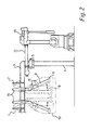
- a vehicle body holding apparatus has a fixed stand 1 comprising four pillars arranged in front and rear pairs.
- the stand 1 supports a main framework 3 which rests upon one pair of the pillars of the stand 1, and is pivoted to the other pair of pillars at 5.
- a hydraulic cylinder or other lifting means is connected to the framework at a connection point 7. In this way, the framework can be rotated upwards around the pivot 5 to adopt the raised position shown in broken lines in Figure 1.
- An inner framework 9 extends downwardly from the main framework 3, and holds holding means such as clamps 11, or other tooling such as a dedicated spot welder.
- the inner framework 9 is located nearer to the mid-line of the apparatus than are the pillars 1 of the fixed stand.
- the holding apparatus In use, the holding apparatus would form part of a work station along a vehicle assembly line.
- the main framework 3 In operation, the main framework 3 would first be lifted into its raised position, carrying the inner framework 9 clear of the path of vehicles passing down the assembly line.
- a part- assembled vehicle body shell typically mounted on a transportation device such as a truck, would be moved between the pillars of the fixed stand 1 to a position under the framework 3.
- the framework 3 is lowered.
- the inner framework 9 is located relatively close to the mid-line of the apparatus, as the main framework 3 is lowered the inner framework 9 passes inside the vehicle body shell.
- the inner framework 9 enters the vehicle body shell through apertures such as those for the front and rear windscreens and an aperture later to be filled by a body roof panel.
- the position adopted by the inner framework 9 at this stage is shown in broken lines in Figure 2.
- the inner framework 9 is movably mounted on the main framework 3, and an actuation means such as a hydraulic cylinder is connected to the inner framework 9 at a connection point 15 in order to move the inner framework relative to the main framework 3.
- an actuation means such as a hydraulic cylinder is connected to the inner framework 9 at a connection point 15 in order to move the inner framework relative to the main framework 3.
- the inner framework will typically comprise left and right halves, each with its own connection point 15.
- the inner framework 9 will now be moved relative to the main framework 3 so as to carry the clamps 11 or other tooling outwardly towards the sides of the vehicle body shell.
- the inner framework 9 will be moved by a predetermined amount, and the clamps 11 or other tooling will have previously been positioned on the inner framework 9 so as to be carried by this movement into the desired positions relative to the vehicle body shell.
- the position now occupied by the inner framework 9 is shown in continuous lines in Figure 2.
- the clamps 11 are now actuated so that clamp pincers or fingers 17 ( Figure 1) grasp the vehicle body shell firmly in a number of places.
- the vehicle body shell is now firmly clamped in position, and assembly operations can now be performed on it.
- the assembly line station may be provided with robots 19 ( Figure 2) which carry out some or all of the assembly operations by means of movable arms 21 ( Figures 2 and 3).
- the inner framework 9 which supports the clamps 11 does not extend outwardly of the sides of the vehicle body shell. Thus it does not interfere with the movement of the robot arms 21 or any other assembly machines or any workers who approach the body shell from the outside.
- tooling used in the assembly operations may be mounted on the inner framework 9 or the main framework 3. This is particularly useful in cases where the tooling has to approach some part of the vehicle body shell from the inside.
- a spot welder for making welds on the inside of a vehicle boot is an example of such a tool.
- the clamps 11 release the vehicle body shell and the main framework 3 is lifted again to carry the inner framework and the clamps 11 clear of the vehicle body. The vehicle body is then carried away to the next station on the assembly line.
- the inner framework 9 includes means, such as slides, to vary the positions of the clamps 11. In this way, the positions at which the apparatus grasps the vehicle body shell can be varied so as to adapt the apparatus for use with different vehicle models. Means for varying the positions of the clamps will tend to increase the bulk of the inner framework 9. However, since the inner framework 9 holds the clamps 11 from inside the vehicle body shell this additional bulk does not obstruct the performance of assembly operations on the outside of the body shell by the robot arms 21 etc.
- the arrangement shown, in which the main framework 3 can be pivoted upwardly from the fixed stand 1 is suitable for incorporation in a pre-existing assembly line since it does not require the vehicle body shell to be raised or lowered by any significant amount.
- holding apparatus embodying the present invention is being incorporated in a new assembly line, it will normally be advantageous to provide means for lifting the vehicle up around the inner framework 9 rather than raising the framework and then lowering it so that the inner framework 9 passes into the vehicle body shell.
- the inner framework 9 can enter the vehicle body shell through other apertures.
- the apparatus can be arranged so that the inner framework enters the vehicle body shell from beneath.
Landscapes
- Engineering & Computer Science (AREA)
- Mechanical Engineering (AREA)
- Manufacturing & Machinery (AREA)
- Chemical & Material Sciences (AREA)
- Combustion & Propulsion (AREA)
- Transportation (AREA)
- Physics & Mathematics (AREA)
- Optics & Photonics (AREA)
- Automobile Manufacture Line, Endless Track Vehicle, Trailer (AREA)
- Automatic Assembly (AREA)
- Confectionery (AREA)
- Constituent Portions Of Griding Lathes, Driving, Sensing And Control (AREA)
Priority Applications (1)
| Application Number | Priority Date | Filing Date | Title |
|---|---|---|---|
| AT87305605T ATE59614T1 (de) | 1987-03-28 | 1987-06-24 | Haltegeraet fuer eine fahrzeugzusammenbaustrasse. |
Applications Claiming Priority (2)
| Application Number | Priority Date | Filing Date | Title |
|---|---|---|---|
| GB8707478 | 1987-03-28 | ||
| GB8707478A GB2206316B (en) | 1987-03-28 | 1987-03-28 | Holding apparatus for a vehicle assembly line |
Publications (3)
| Publication Number | Publication Date |
|---|---|
| EP0284680A2 true EP0284680A2 (fr) | 1988-10-05 |
| EP0284680A3 EP0284680A3 (en) | 1989-05-24 |
| EP0284680B1 EP0284680B1 (fr) | 1991-01-02 |
Family
ID=10614863
Family Applications (1)
| Application Number | Title | Priority Date | Filing Date |
|---|---|---|---|
| EP87305605A Expired - Lifetime EP0284680B1 (fr) | 1987-03-28 | 1987-06-24 | Appareil de préhension pour une ligne d'assemblage de véhicules |
Country Status (7)
| Country | Link |
|---|---|
| US (1) | US4795075A (fr) |
| EP (1) | EP0284680B1 (fr) |
| AT (1) | ATE59614T1 (fr) |
| AU (1) | AU592012B2 (fr) |
| DE (1) | DE3766956D1 (fr) |
| ES (1) | ES2006210A6 (fr) |
| GB (1) | GB2206316B (fr) |
Cited By (5)
| Publication number | Priority date | Publication date | Assignee | Title |
|---|---|---|---|---|
| FR2717764A1 (fr) * | 1994-03-22 | 1995-09-29 | Progressive Tool & Ind Co | Appareil de montage pour chaine de fabrication. |
| US5486083A (en) * | 1994-10-06 | 1996-01-23 | J Star Consolidated | Process and apparatus for handling a vehicle frame |
| WO2000076719A3 (fr) * | 1999-06-12 | 2001-04-12 | Thyssenkrupp Ind Ag | Cadre de serrage pour pieces laterales d'automobile |
| CN103192333A (zh) * | 2013-04-10 | 2013-07-10 | 江苏润邦重工股份有限公司 | 用于装配胎架小车的装配胎模 |
| CN109531495A (zh) * | 2018-12-31 | 2019-03-29 | 湖北汉唐智能科技股份有限公司 | 商用车平衡轴横梁装配方法 |
Families Citing this family (22)
| Publication number | Priority date | Publication date | Assignee | Title |
|---|---|---|---|---|
| US5104659A (en) * | 1984-05-31 | 1992-04-14 | American Cyanamid Company | Compositions, devices and method for controlling insects |
| US5011068A (en) * | 1989-12-05 | 1991-04-30 | Progressive Tool & Industries Co. | Automotive body framing system |
| US5374799A (en) * | 1991-01-30 | 1994-12-20 | Mazda Motor Corporation | Method for the assembly of automotive vehicle bodies and a jig unit therefor |
| IT1261262B (it) * | 1993-09-15 | 1996-05-09 | Comau Spa | Dispositivo per la saldatura a punti di strutture costituite da elementi di lamiera stampata |
| US6173881B1 (en) * | 1998-11-11 | 2001-01-16 | Progressive Tool & Industries Company | Car body assembly and welding station with reciprocal gate-supporting system |
| CA2323114C (fr) * | 1999-11-18 | 2007-12-11 | Honda Giken Kogyo Kabushiki Kaisha | Assembleuse de plancher de vehicule |
| DE10039593A1 (de) * | 2000-08-12 | 2002-02-21 | Daimler Chrysler Ag | Verfahren und Spannrahmen zum Fügen mehrerer Bauteil-Einzelteile zu einem komplexen zusammengesetzten Bauteil |
| DE10163391A1 (de) * | 2001-12-21 | 2003-07-03 | Audi Ag | Verfahren zur Verbindung von Karosseriebauteilen mit einer Verbindungsnaht |
| US6932263B2 (en) * | 2002-04-08 | 2005-08-23 | Progressive Tool & Industries Co. | Vehicle framing system for plurality of vehicle body styles |
| DE20306257U1 (de) * | 2003-04-17 | 2004-08-19 | Kuka Schweissanlagen Gmbh | Bearbeitungsvorrichtung |
| US8201723B2 (en) * | 2008-03-12 | 2012-06-19 | Comau, Inc. | Robotic high density welding body shop |
| US8713780B2 (en) | 2008-05-13 | 2014-05-06 | Comau, Inc. | High density welding subassembly machine |
| CN103522109B (zh) * | 2013-10-08 | 2015-09-09 | 上海新世纪机器人有限公司 | 生产流水线随行组合式定位工装 |
| CA3008600C (fr) | 2014-12-15 | 2022-09-13 | Comau Llc | Systeme et procede d'assemblage de vehicule modulaire |
| JP6092909B2 (ja) * | 2015-02-10 | 2017-03-08 | 富士重工業株式会社 | 車体の製造装置 |
| US10384873B2 (en) | 2016-05-06 | 2019-08-20 | Comau Llc | Inverted carrier lift device system and method |
| CN106078922A (zh) * | 2016-06-27 | 2016-11-09 | 苏州安特实业有限公司 | 一种台式操作台 |
| CN106826068A (zh) * | 2017-03-21 | 2017-06-13 | 天津芮盛汽车部件有限公司 | 焊接夹具装置 |
| PL3707096T3 (pl) | 2017-11-07 | 2024-09-23 | Comau Llc | System transportowy oraz sposoby |
| US11420853B2 (en) | 2019-10-03 | 2022-08-23 | Comau Llc | Assembly material logistics system and methods |
| PL4161851T3 (pl) | 2020-06-08 | 2025-12-08 | Comau Llc | Układ i sposoby logistyki materiałów montażowych |
| US20240239427A1 (en) * | 2023-01-13 | 2024-07-18 | Andrew Brown | Transportable Folding Storage Apparatus for Removable Vehicular Doors and Hardtop Roofs |
Family Cites Families (12)
| Publication number | Priority date | Publication date | Assignee | Title |
|---|---|---|---|---|
| US2215693A (en) * | 1938-07-16 | 1940-09-24 | Chrysler Corp | Welding apparatus |
| GB1461432A (en) * | 1974-06-25 | 1977-01-13 | Siv Deltix Spa | Welding machine |
| US4162387A (en) * | 1977-03-14 | 1979-07-24 | Ettore De Candia | Car body welding assembly system |
| US4316072A (en) * | 1979-09-17 | 1982-02-16 | Ductmate Industries, Inc. | Apparatus for positioning and securing components of a workpiece |
| GB2059303B (en) * | 1979-09-25 | 1983-06-02 | Nissan Motor | Two-shift automatic assembling apparatus |
| JPS56152542A (en) * | 1980-04-25 | 1981-11-26 | Honda Motor Co Ltd | Assembly and conveying device for vehicle body |
| JPS58119474A (ja) * | 1982-01-09 | 1983-07-15 | Honda Motor Co Ltd | 自動車車体の増打溶接装置 |
| IT1152517B (it) * | 1982-09-02 | 1987-01-07 | Rosa Gaetano Di | Impianto automatico per assemblaggio e saldatura di scocche di autoveicoli |
| FR2558092B1 (fr) * | 1984-01-12 | 1986-05-30 | Sciaky Sa | Installation pour l'assemblage de plusieurs modeles de carrosseries d'un meme type de vehicule automobile |
| IT1173481B (it) * | 1984-03-26 | 1987-06-24 | Rosa Gaetano Di | Impianto automatico per l'assemblaggio e saldatura di scocche di autoveicoli,dotato di un ritmo produttivo altissimo,mantenibili anche in concomitanza del cambio del modello in linea e quindi del cambio dei conformatori |
| JPS6112474A (ja) * | 1984-06-26 | 1986-01-20 | Toyota Motor Corp | 車体組立装置 |
| FR2580973B1 (fr) * | 1985-04-30 | 1989-12-22 | Renault Automation | Procede et dispositif d'assemblage destines notamment aux lignes capacitaires de carrosseries |
-
1987
- 1987-03-28 GB GB8707478A patent/GB2206316B/en not_active Expired - Fee Related
- 1987-06-24 AT AT87305605T patent/ATE59614T1/de not_active IP Right Cessation
- 1987-06-24 EP EP87305605A patent/EP0284680B1/fr not_active Expired - Lifetime
- 1987-06-24 DE DE8787305605T patent/DE3766956D1/de not_active Expired - Fee Related
- 1987-07-18 US US07/079,799 patent/US4795075A/en not_active Expired - Lifetime
- 1987-08-27 ES ES8702490A patent/ES2006210A6/es not_active Expired
- 1987-09-08 AU AU78136/87A patent/AU592012B2/en not_active Ceased
Cited By (6)
| Publication number | Priority date | Publication date | Assignee | Title |
|---|---|---|---|---|
| FR2717764A1 (fr) * | 1994-03-22 | 1995-09-29 | Progressive Tool & Ind Co | Appareil de montage pour chaine de fabrication. |
| US5486083A (en) * | 1994-10-06 | 1996-01-23 | J Star Consolidated | Process and apparatus for handling a vehicle frame |
| WO2000076719A3 (fr) * | 1999-06-12 | 2001-04-12 | Thyssenkrupp Ind Ag | Cadre de serrage pour pieces laterales d'automobile |
| CN103192333A (zh) * | 2013-04-10 | 2013-07-10 | 江苏润邦重工股份有限公司 | 用于装配胎架小车的装配胎模 |
| CN103192333B (zh) * | 2013-04-10 | 2015-08-12 | 江苏润邦重工股份有限公司 | 用于装配胎架小车的装配胎模 |
| CN109531495A (zh) * | 2018-12-31 | 2019-03-29 | 湖北汉唐智能科技股份有限公司 | 商用车平衡轴横梁装配方法 |
Also Published As
| Publication number | Publication date |
|---|---|
| DE3766956D1 (de) | 1991-02-07 |
| AU592012B2 (en) | 1989-12-21 |
| GB8707478D0 (en) | 1987-04-29 |
| ATE59614T1 (de) | 1991-01-15 |
| GB2206316B (en) | 1991-03-20 |
| GB2206316A (en) | 1989-01-05 |
| ES2006210A6 (es) | 1989-04-16 |
| US4795075A (en) | 1989-01-03 |
| AU7813687A (en) | 1988-09-29 |
| JPS641667A (en) | 1989-01-06 |
| EP0284680B1 (fr) | 1991-01-02 |
| EP0284680A3 (en) | 1989-05-24 |
Similar Documents
| Publication | Publication Date | Title |
|---|---|---|
| EP0284680B1 (fr) | Appareil de préhension pour une ligne d'assemblage de véhicules | |
| EP0658397A2 (fr) | Dispositif de soudage pour points de structures constituées d'éléments en tôle, en particulier de véhicules motorisés | |
| US5374799A (en) | Method for the assembly of automotive vehicle bodies and a jig unit therefor | |
| US5943768A (en) | Automotive framing system | |
| JPS61295184A (ja) | ドア−又は類似の開閉構成要素の自動取付プラント | |
| JPH05139348A (ja) | 自動車のトランクリツド組付装置 | |
| JP2000198473A (ja) | 自動車ガラス装着システム | |
| US5456002A (en) | Apparatus for installing instrument panel assemblies in automotive vehicle bodies | |
| JPH0659851B2 (ja) | 複数種の車体モデルの組付け方法 | |
| US5311659A (en) | Apparatus for installing instrument panel assemblies in automotive vehicle bodies | |
| JPH07136798A (ja) | 自動車車体の組立方法及び組立装置 | |
| EP0513453A1 (fr) | Poste de travail | |
| JPH08257762A (ja) | 車両のルーフ溶接装置 | |
| JP2974259B2 (ja) | 自動車車体の組立方法及びその組付治具装置 | |
| US5351384A (en) | Method of installing instrument panel assemblies in automotive vehicle bodies | |
| JP2850261B2 (ja) | ボンネットとフロントフェンダの組付方法及び装置 | |
| JPH0575533B2 (fr) | ||
| JPH011667A (ja) | 部分的に組立てられた自動車ボディを保持するための保持装置 | |
| JP2974262B2 (ja) | 自動車車体の組立方法 | |
| JP2658670B2 (ja) | 車体パネルの組立装置 | |
| JPH0560732U (ja) | ワーク挿入装置 | |
| JP2993311B2 (ja) | 溶接装置 | |
| JP3080733B2 (ja) | 車両のワーク搭載方法およびその装置 | |
| JPH06654A (ja) | 自動車車体の増打溶接装置 | |
| JP2974260B2 (ja) | 自動車車体の組立方法及びその組付治具装置 |
Legal Events
| Date | Code | Title | Description |
|---|---|---|---|
| PUAI | Public reference made under article 153(3) epc to a published international application that has entered the european phase |
Free format text: ORIGINAL CODE: 0009012 |
|
| AK | Designated contracting states |
Kind code of ref document: A2 Designated state(s): AT BE CH DE FR GR IT LI LU NL SE |
|
| 17P | Request for examination filed |
Effective date: 19881115 |
|
| RAP1 | Party data changed (applicant data changed or rights of an application transferred) |
Owner name: LITTON U.K. LIMITED |
|
| PUAL | Search report despatched |
Free format text: ORIGINAL CODE: 0009013 |
|
| AK | Designated contracting states |
Kind code of ref document: A3 Designated state(s): AT BE CH DE FR GR IT LI LU NL SE |
|
| 17Q | First examination report despatched |
Effective date: 19891218 |
|
| ITF | It: translation for a ep patent filed | ||
| GRAA | (expected) grant |
Free format text: ORIGINAL CODE: 0009210 |
|
| AK | Designated contracting states |
Kind code of ref document: B1 Designated state(s): AT BE CH DE FR GR IT LI LU NL SE |
|
| PG25 | Lapsed in a contracting state [announced via postgrant information from national office to epo] |
Ref country code: LI Effective date: 19910102 Ref country code: GR Free format text: LAPSE BECAUSE OF FAILURE TO SUBMIT A TRANSLATION OF THE DESCRIPTION OR TO PAY THE FEE WITHIN THE PRESCRIBED TIME-LIMIT Effective date: 19910102 Ref country code: CH Effective date: 19910102 Ref country code: AT Effective date: 19910102 |
|
| REF | Corresponds to: |
Ref document number: 59614 Country of ref document: AT Date of ref document: 19910115 Kind code of ref document: T |
|
| REF | Corresponds to: |
Ref document number: 3766956 Country of ref document: DE Date of ref document: 19910207 |
|
| ET | Fr: translation filed | ||
| REG | Reference to a national code |
Ref country code: CH Ref legal event code: PL |
|
| PG25 | Lapsed in a contracting state [announced via postgrant information from national office to epo] |
Ref country code: LU Free format text: LAPSE BECAUSE OF NON-PAYMENT OF DUE FEES Effective date: 19910630 |
|
| PLBE | No opposition filed within time limit |
Free format text: ORIGINAL CODE: 0009261 |
|
| STAA | Information on the status of an ep patent application or granted ep patent |
Free format text: STATUS: NO OPPOSITION FILED WITHIN TIME LIMIT |
|
| 26N | No opposition filed | ||
| NLS | Nl: assignments of ep-patents |
Owner name: LITCOM U.K. LIMITED TE AYLESBURY, GROOT-BRITTANNIE |
|
| PGFP | Annual fee paid to national office [announced via postgrant information from national office to epo] |
Ref country code: BE Payment date: 19940607 Year of fee payment: 8 |
|
| ITPR | It: changes in ownership of a european patent |
Owner name: CAMBIO RAGIONE SOCIALE;WESTERN ATLAS U.K. LIMITED |
|
| NLT1 | Nl: modifications of names registered in virtue of documents presented to the patent office pursuant to art. 16 a, paragraph 1 |
Owner name: WESTERN ATLAS U.K. LIMITED TE LONDEN, GROOT-BRITTA |
|
| PGFP | Annual fee paid to national office [announced via postgrant information from national office to epo] |
Ref country code: NL Payment date: 19940630 Year of fee payment: 8 |
|
| REG | Reference to a national code |
Ref country code: FR Ref legal event code: CD |
|
| EAL | Se: european patent in force in sweden |
Ref document number: 87305605.5 |
|
| PG25 | Lapsed in a contracting state [announced via postgrant information from national office to epo] |
Ref country code: BE Effective date: 19950630 |
|
| BERE | Be: lapsed |
Owner name: WESTERN ATLAS U.K. LTD Effective date: 19950630 |
|
| PG25 | Lapsed in a contracting state [announced via postgrant information from national office to epo] |
Ref country code: NL Effective date: 19960101 |
|
| NLV4 | Nl: lapsed or anulled due to non-payment of the annual fee |
Effective date: 19960101 |
|
| PGFP | Annual fee paid to national office [announced via postgrant information from national office to epo] |
Ref country code: FR Payment date: 20000627 Year of fee payment: 14 |
|
| PGFP | Annual fee paid to national office [announced via postgrant information from national office to epo] |
Ref country code: SE Payment date: 20000630 Year of fee payment: 14 |
|
| PGFP | Annual fee paid to national office [announced via postgrant information from national office to epo] |
Ref country code: DE Payment date: 20000722 Year of fee payment: 14 |
|
| PG25 | Lapsed in a contracting state [announced via postgrant information from national office to epo] |
Ref country code: SE Free format text: LAPSE BECAUSE OF NON-PAYMENT OF DUE FEES Effective date: 20010625 |
|
| EUG | Se: european patent has lapsed |
Ref document number: 87305605.5 |
|
| PG25 | Lapsed in a contracting state [announced via postgrant information from national office to epo] |
Ref country code: FR Free format text: LAPSE BECAUSE OF NON-PAYMENT OF DUE FEES Effective date: 20020228 |
|
| PG25 | Lapsed in a contracting state [announced via postgrant information from national office to epo] |
Ref country code: DE Free format text: LAPSE BECAUSE OF NON-PAYMENT OF DUE FEES Effective date: 20020403 |
|
| PG25 | Lapsed in a contracting state [announced via postgrant information from national office to epo] |
Ref country code: IT Free format text: LAPSE BECAUSE OF NON-PAYMENT OF DUE FEES;WARNING: LAPSES OF ITALIAN PATENTS WITH EFFECTIVE DATE BEFORE 2007 MAY HAVE OCCURRED AT ANY TIME BEFORE 2007. THE CORRECT EFFECTIVE DATE MAY BE DIFFERENT FROM THE ONE RECORDED. Effective date: 20050624 |