EP0284709A2 - Ventilateur résersible - Google Patents
Ventilateur résersible Download PDFInfo
- Publication number
- EP0284709A2 EP0284709A2 EP87890299A EP87890299A EP0284709A2 EP 0284709 A2 EP0284709 A2 EP 0284709A2 EP 87890299 A EP87890299 A EP 87890299A EP 87890299 A EP87890299 A EP 87890299A EP 0284709 A2 EP0284709 A2 EP 0284709A2
- Authority
- EP
- European Patent Office
- Prior art keywords
- wing
- fan
- rotation
- fan according
- wing surface
- Prior art date
- Legal status (The legal status is an assumption and is not a legal conclusion. Google has not performed a legal analysis and makes no representation as to the accuracy of the status listed.)
- Granted
Links
Images



Classifications
-
- F—MECHANICAL ENGINEERING; LIGHTING; HEATING; WEAPONS; BLASTING
- F04—POSITIVE - DISPLACEMENT MACHINES FOR LIQUIDS; PUMPS FOR LIQUIDS OR ELASTIC FLUIDS
- F04D—NON-POSITIVE-DISPLACEMENT PUMPS
- F04D25/00—Pumping installations or systems
- F04D25/16—Combinations of two or more pumps ; Producing two or more separate gas flows
- F04D25/166—Combinations of two or more pumps ; Producing two or more separate gas flows using fans
-
- F—MECHANICAL ENGINEERING; LIGHTING; HEATING; WEAPONS; BLASTING
- F04—POSITIVE - DISPLACEMENT MACHINES FOR LIQUIDS; PUMPS FOR LIQUIDS OR ELASTIC FLUIDS
- F04D—NON-POSITIVE-DISPLACEMENT PUMPS
- F04D19/00—Axial-flow pumps
- F04D19/002—Axial flow fans
- F04D19/005—Axial flow fans reversible fans
-
- F—MECHANICAL ENGINEERING; LIGHTING; HEATING; WEAPONS; BLASTING
- F04—POSITIVE - DISPLACEMENT MACHINES FOR LIQUIDS; PUMPS FOR LIQUIDS OR ELASTIC FLUIDS
- F04D—NON-POSITIVE-DISPLACEMENT PUMPS
- F04D29/00—Details, component parts, or accessories
- F04D29/26—Rotors specially for elastic fluids
- F04D29/32—Rotors specially for elastic fluids for axial flow pumps
- F04D29/38—Blades
- F04D29/382—Flexible blades
Definitions
- the invention relates to a fan with a reversible direction of rotation for changing the conveying direction, in particular for air circulation in wood drying systems, with blades attached to the fan shaft, of which each blade has at least two substantially radially extending blade carriers, which together carry a blade surface.
- Axial fans with a diameter of 10 cm up to 4 m are used to move large amounts of air with low air resistance. These fans have blades made of sheet metal or profile blades; Full profiles are e.g. above a certain power, which depends on the Reynolds number, e.g. when higher air outputs with greater resistance and higher peripheral speeds are to be achieved.
- GB-PS 581 956, GB-PS 15 113 (AD 1908), GB-PS 8 777 (AD 1908), US-PS 511 442 and GB-PS 1 509 903 fans are different Structure known that can not be used with an acceptable level of efficiency for operation with reversible direction of rotation with simultaneous change of conveying direction.
- fans that are intended to convey in opposite directions can be solved in various ways.
- reversible fans are used, for which a straight or double-sided blade is used, so that it does not matter in which direction the fan rotates.
- the air performance is poor in both directions of rotation, since the fan blades, which have the same profile in both directions, are not very efficient.
- fans in their or with their suspensions can be rotated around an off-axis bearing, so that they can be pivoted in one or the opposite direction.
- the turning of the blades can be adjusted in the opposite direction by a turning mechanism in fans.
- these solutions are unsatisfactory, since such constructions are complex and relatively expensive and the effort-efficiency ratio is not optimal.
- the object of the invention is to create a fan which can be used in reversible operation and which has a largely optimal efficiency in both directions of rotation.
- This is achieved according to the invention in a fan of the type mentioned at the outset in that, in order to adapt the wing surfaces to an ideal air-directing or wing profile, the width of the flexible wing surface is greater than the respective internal distance between the wing carriers or the elastically stretchable wing surfaces during the rotation by the Air pressure can be expanded in an arc shape, so that the wing surface can be moved or expanded unhindered in accordance with the directions of rotation from one side to the other side of a plane spanned by the two wing carriers.
- the fan blade has the wing-bearing Wing carriers which carry wing surfaces made of thin plates or foils made of sheet metal or plastic or a covering made of textile or plastic fabric.
- the wing surfaces When the fan is turned, the wing surfaces almost completely adopt an ideal air duct or wing profile. Because the width of the wing area is greater than the respective distance between the wing carriers, the wing area can bulge in a direction opposite to the conveying direction of the fan during operation and assume a wing profile which is adapted to an ideal air flow pattern.
- the efficiency of the fan according to the invention is not completely equivalent to that of conventional axial fans, the wing profile of which is optimally selected and the blades of which are made of sheet metal or hollow profiles, but it is up to 90-95% of the efficiency of these fans which only promote in one direction. so that due to the simplicity of the construction of the reversible direction of rotation fan according to the invention, this disadvantage of the reduced efficiency is not significant.
- each folded end in the plane of the wing surface having play for a displacement and / or pivoting with respect to the longitudinal support has or if wing surfaces made of canvas, fabric, plastic fabric or the like. with their lateral ends or flanks, e.g. in the form of loops, preferably fixed, are connected to the wing carriers.
- a good efficiency results if the deflection of the wing surface to the width of the wing surface or to the inner distance of the wing carrier delimiting the wing surface is in a ratio of 1: 5 to 1:20, preferably of 1:10, or when in operation Direction of rotation or plane of rotation forms a tangent to the leading end of the wing surface.
- the directions of rotation of the fans can also be periodically reversed, for example, so that the general spatial flow path of the air in the system remains the same, but the flow direction is changed by 180 °.
- a heating device is preferably assigned to each fan in a manner known per se. This can be controlled by a controller, wherein a thermocouple for individual detection and control of the heating power of the heating device of this fan is preferably assigned to each fan or its air flow. In this way, the heat can be supplied correctly in direct relation to the water output of the wood piles, which results in lower heat consumption.
- a further embodiment of the invention is characterized in that an air velocity measuring probe is preferably assigned to each fan or its air flow, so that the air velocity can be regulated individually.
- the speed of the fans is regulated by the air speed measuring probes in such a way that with different wood thicknesses, in particular with different stacking slats and differently laid boards, an air speed corresponding to the program can be adjusted.
- each fan's speed can be changed suddenly in order to change the air flow by volume pulses.
- the air flow can be adapted to the drying process by volume pulses. The purpose of these impulses is to replace the laminar boundary climate on the wood surface with a turbulent flow.
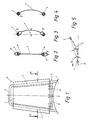
- Fig. 1 shows a shaft 1 of a fan, on which a frame structure 2 of a fan blade 3 is attached in relation to the shaft.
- the frame structure 2 has wing carriers 4 which extend essentially radially from the shaft 1 and are connected on the outside by a web 5, preferably in one piece. In the area of the shaft 1, the wing carriers 4 can be connected by means of a crossbar 6.
- wing surface 7 a flexible, thin metal or plastic plate or foil is provided as wing surface 7; 2 shows, as already mentioned, a section along the line II-II of FIG. 1. It can be seen that the wing surface 7 surrounds the side members 4 with their flanks or lateral ends and is bent back on or towards itself, the flanks or lateral ends of the wing surface at 8 on the wing surface 7 even by riveting, gluing, welding, spot welding or the like. are attached. The flanks or lateral ends of the wing surface 7 are bent around the wing carrier 4 to form loops 9 in such a way that a free space or channel 9 'is formed which displaces the area of the wing surface or the loops 9 transversely to the wing carriers 4 enables.
- the size of the deflection d in the longitudinal direction of the wing surface 7 can be changed.
- the deflection d in the region near the shaft is chosen to be greater than in the region of the outer web 5 This can be achieved by appropriate selection of the size of the loops 9 along the side members 4.
- the deflection d can be caused by the distance between the Wing carriers 4 exceeding width of the wing surface 7 in the longitudinal direction of the wing carrier 4 can be changed continuously or discontinuously.
- Fig. 4 shows essentially the same structure of the wing as Figs. 1 to 3, but as wing surface 7 is a canvas, a fabric, e.g. a plastic fabric or the like. intended.
- the lateral ends or flanks of the wing surface 7 are fastened to the wing carriers 4 with little or no play, e.g. glued, clamped, or fastened by turning over in the form of a narrow loop 9 and / or sewing, in particular in order to avoid fluttering of the fabric or fabric when the direction of rotation changes.
- a fastening device 10 e.g. a loop, as shown in dash-dotted lines in Fig. 1, may be provided, which is attached to the inner lower end of the wing surface 7 and extends around the crossbar 6, so that radial movement of the soft wing surface 7 is prevented outwards.
- Fig. 5 shows a section through a fan blade 3 in operation.
- the wing surface 7 takes a course such that the straight line parallel to the direction of rotation 11 of the fan or the fan blade 3 can be applied as a tangent 13 to the wing surface 7 when the wing carrier 4 leads in the direction of rotation by choosing the deflection d is.
- the flanks or lateral ends of the wings advantageously include the wing carriers 4 with the formation of channels or loops 9 with play.
- the plane spanned by the wing carriers 4 set in relation to the direction of rotation includes an angle ⁇ of approximately 15 to 20 ° with the direction of rotation or plane of rotation.
- the deflection of the wing surface 7 is in a ratio of 1: 5 to 1:20, preferably of about 1:10, to the width of the wing surface or to the inner distance of the wing carrier 4 delimiting the wing surface.
- the width of the wing surface 7 is understood to mean its width in the unmounted or flat state. This width must always be greater than the space between the wing supports 4, otherwise - except for an elastic, stretchable material - the wing surface 7 could not bulge or bend. Not included in the definition of the width are those parts of the wing surface 7 which are firmly connected to the wing carriers 4 (for example the coverings of the wing carriers 4 according to FIG. 4) and cannot contribute to bulging of the wing surface.
- the loops 9 rotate about the wing carrier 4 when the direction of rotation of the wing surface 7 is changed and the deflection d changes to the other side of the wing plane due to the air pressure.
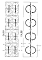
- the basic unit formed from four square fans 1 ⁇ , 2 ⁇ , 3 ⁇ , 4 ⁇ with reversible direction of rotation is shown in four different operating states.
- the fans 1 ⁇ , 2 ⁇ , 3 ⁇ , 4 ⁇ are arranged in a wall W dividing or closing the drying chamber K (see FIGS. 10-13).
- the reference character R denotes the flow path or the flow direction of the air indicated by arrows. It is assumed that when the fan 1 ⁇ rotates clockwise, an air flow directed at the viewer of FIG. 6 is generated, and thus this fan acts as a pressure fan (reference symbol D) with respect to the viewer.
- the two upper fans 1 ⁇ and 3 ⁇ work as pressure or suction fans and also the two lower fans 2 ⁇ and 4 ⁇ as D and S fans, the horizontal is shown, from left to right air flow R.
- 10A and 10B show in elevation and section plan, respectively, a multiple arrangement of the basic unit shown in FIGS. 6-9, i.e. of a total of four such basic units, arranged in an upright partition W of the drying chamber K.
- 10 B shows the lower half of FIG. 10 A.
- the individual fans are identified by the reference numerals 1 ⁇ , 2 ⁇ , 3 ⁇ , 4 ⁇ ; 1.1.2.1.3.1.4.1; 1.2.2.2.3.2.4.2; 1.3.2.3.3.3.4.3 provide and run in the manner shown as S or D fans. As indicated by the arrows R of the air flow, this results in a quasi "opposite" (i.e. one with an alternating, opposite direction of rotation in plan) horizontal flow.
- FIGS. 11 A and 11 B show in the same way and with the same reference numerals or the same symbols as FIGS. 10 A and 10 B a quasi "same-direction" horizontal flow.
- FIGS. 10 A and 10 B show in the same way and with the same reference numerals or the same symbols as FIGS. 10 A and 10 B an "opposite" vertical flow.
- FIGS. 13 A and 13 B show in the same way and with the same reference numerals or the same symbols as FIGS. 10 A and 10 B, a "same-direction" vertical flow.
- FIGS. 12 and 13 only applies to the drying chambers K arranged in the floor plan next to the fan wall W, whereas the flow in the area of the fan wall W runs horizontally.
Landscapes
- Engineering & Computer Science (AREA)
- Mechanical Engineering (AREA)
- General Engineering & Computer Science (AREA)
- Structures Of Non-Positive Displacement Pumps (AREA)
- Drying Of Solid Materials (AREA)
Applications Claiming Priority (2)
| Application Number | Priority Date | Filing Date | Title |
|---|---|---|---|
| AT793/87 | 1987-04-01 | ||
| AT79387A AT403734B (de) | 1987-04-01 | 1987-04-01 | Anordnung von axialventilatoren für holztrocknungsanlagen |
Publications (3)
| Publication Number | Publication Date |
|---|---|
| EP0284709A2 true EP0284709A2 (fr) | 1988-10-05 |
| EP0284709A3 EP0284709A3 (en) | 1989-03-01 |
| EP0284709B1 EP0284709B1 (fr) | 1991-04-10 |
Family
ID=3499896
Family Applications (1)
| Application Number | Title | Priority Date | Filing Date |
|---|---|---|---|
| EP19870890299 Expired - Lifetime EP0284709B1 (fr) | 1987-04-01 | 1987-12-30 | Ventilateur résersible |
Country Status (4)
| Country | Link |
|---|---|
| EP (1) | EP0284709B1 (fr) |
| AT (1) | AT403734B (fr) |
| DE (1) | DE3769311D1 (fr) |
| GR (1) | GR3002007T3 (fr) |
Cited By (5)
| Publication number | Priority date | Publication date | Assignee | Title |
|---|---|---|---|---|
| GB2237330B (en) * | 1989-10-07 | 1994-08-24 | John Nicoll Vannan | Semi flexible vane and fluid machine incorporating a plurality of such vanes |
| AT407797B (de) * | 1999-01-29 | 2001-06-25 | Theodor Dr Vanicek | Trocknungsanlage |
| US7434743B2 (en) * | 2005-01-28 | 2008-10-14 | Hewlett-Packard Development Company, L.P. | Reversible fan of electronic module |
| WO2008154791A1 (fr) * | 2007-06-19 | 2008-12-24 | Shenzhen Lianchuang Industry Co., Ltd. | Appareil de climatisation domestique ultra-mince |
| EP2631580A1 (fr) * | 2012-02-22 | 2013-08-28 | Bühler AG | Séchage d'aliments, notamment de produits à base de pâtes, doté d'un battant de ventilateur comprenant une matière plastique |
Families Citing this family (1)
| Publication number | Priority date | Publication date | Assignee | Title |
|---|---|---|---|---|
| AT404876B (de) * | 1995-05-16 | 1999-03-25 | Andritz Patentverwaltung | Verfahren zum trocknen von feuchtem gut, insbesonders von holzfasern und anlage zur durchführung dieses verfahrens |
Family Cites Families (8)
| Publication number | Priority date | Publication date | Assignee | Title |
|---|---|---|---|---|
| DE323848C (de) * | 1920-08-13 | Aeg | Stoffschaufel fuer Zentrifugalventilmotoren | |
| US1976410A (en) * | 1931-06-08 | 1934-10-09 | Howard B Oakleaf | Lumber drying apparatus for yard use |
| US2149267A (en) * | 1936-04-02 | 1939-03-07 | Gen Motors Corp | Fan |
| DE694061C (de) * | 1937-12-05 | 1940-07-24 | Siemens Schuckertwerke Akt Ges | Raumfaecher, Tischfaecher, Wandfaecher o. dgl. |
| GB581956A (en) * | 1944-06-12 | 1946-10-30 | John Newton Collins | Improvements relating to air impellers or fans |
| EP0043959B1 (fr) * | 1980-07-11 | 1984-08-29 | Niro Plan Ag | Four à circulation d'air chauffé à gaz ou électriquement pour cuire des denrées alimentaires |
| DE3321673C2 (de) * | 1983-06-15 | 1985-05-30 | Max 8908 Krumbach Wagner | Verfahren und Vorrichtung zum Trocknen von keramischen Formlingen |
| DE3340489A1 (de) * | 1983-11-09 | 1985-08-14 | Lignomat GmbH, 7148 Remseck | Verfahren zum trocknen von schnittholz |
-
1987
- 1987-04-01 AT AT79387A patent/AT403734B/de not_active IP Right Cessation
- 1987-12-30 EP EP19870890299 patent/EP0284709B1/fr not_active Expired - Lifetime
- 1987-12-30 DE DE8787890299T patent/DE3769311D1/de not_active Expired - Lifetime
-
1991
- 1991-05-28 GR GR91400681T patent/GR3002007T3/el unknown
Cited By (7)
| Publication number | Priority date | Publication date | Assignee | Title |
|---|---|---|---|---|
| GB2237330B (en) * | 1989-10-07 | 1994-08-24 | John Nicoll Vannan | Semi flexible vane and fluid machine incorporating a plurality of such vanes |
| AT407797B (de) * | 1999-01-29 | 2001-06-25 | Theodor Dr Vanicek | Trocknungsanlage |
| US7434743B2 (en) * | 2005-01-28 | 2008-10-14 | Hewlett-Packard Development Company, L.P. | Reversible fan of electronic module |
| GB2422727B (en) * | 2005-01-28 | 2009-08-19 | Hewlett Packard Development Co | Reversible fan of electronic module |
| WO2008154791A1 (fr) * | 2007-06-19 | 2008-12-24 | Shenzhen Lianchuang Industry Co., Ltd. | Appareil de climatisation domestique ultra-mince |
| EP2631580A1 (fr) * | 2012-02-22 | 2013-08-28 | Bühler AG | Séchage d'aliments, notamment de produits à base de pâtes, doté d'un battant de ventilateur comprenant une matière plastique |
| WO2013124220A1 (fr) * | 2012-02-22 | 2013-08-29 | Bühler AG | Séchage de produits alimentaires, en particulier de pâtes, avec une pale de ventilateur contenant du plastique |
Also Published As
| Publication number | Publication date |
|---|---|
| ATA79387A (de) | 1997-09-15 |
| EP0284709B1 (fr) | 1991-04-10 |
| DE3769311D1 (de) | 1991-05-16 |
| GR3002007T3 (en) | 1992-12-30 |
| EP0284709A3 (en) | 1989-03-01 |
| AT403734B (de) | 1998-05-25 |
Similar Documents
| Publication | Publication Date | Title |
|---|---|---|
| EP0315943B1 (fr) | Plancher surélevé pour l'extraction de l'air hors d'une pièce | |
| DE2253170C2 (de) | Verfahren und Vorrichtung zum Behandeln einer frei schwebend geführten Materialbahn | |
| DE1938529B2 (de) | Vorrichtung zum fuehren einer in laengsrichtung beweglichen bahn aus papier o.dgl. durch luftstrahlen | |
| DE19922165C2 (de) | Trockner für band- oder plattenförmiges Gut | |
| DE3343811A1 (de) | Saugriemenfoerderer | |
| DE29700769U1 (de) | Trockner für Gipskartonplatten | |
| EP0284709B1 (fr) | Ventilateur résersible | |
| DE202009007057U1 (de) | Luftkissentisch | |
| DE19619547A1 (de) | Luftkissendüse und Vorrichtung zur Wärmebehandlung einer kontinuierlich bewegten Warenbahn mit Luftkissendüsen | |
| EP3120085B1 (fr) | Dispositif de ventilation | |
| DE19905095C2 (de) | Bogenführungseinrichtung für eine Druckmaschine | |
| EP0586784B1 (fr) | Dispositif d'élaboration d'un système de circulation d'air pour le traitement de matériau en bande continue | |
| DE2328186C2 (de) | Induktionsgerät | |
| EP2288855B1 (fr) | Sortie d'air | |
| EP2746198B1 (fr) | Utilisation d'un dispositif de transport | |
| EP0695715B1 (fr) | Dispositif pour un appareil de sortie de feuilles | |
| DE69500781T2 (de) | Luftleitflügel für eine pneumatische Wendestange | |
| DE102020004454A1 (de) | Trockner zum Trocknen eines plattenförmigen Guts | |
| DE2838400C2 (de) | Luftauslaß zur Belüftung von Räumen | |
| DE4003956A1 (de) | Unterdruckduesensystem zur behandlung von beweglichen materialbahnen | |
| AT399024B (de) | Axialventilator | |
| CH658119A5 (de) | Lueftungsvorrichtung fuer einen raum mit zwei getrennten stroemungswegen zur be- und entlueftung. | |
| EP1652666B1 (fr) | Superstructure pour une machine à imprimer | |
| DE19915923C2 (de) | Umlufttrockner | |
| EP4224077B1 (fr) | Passage d'air |
Legal Events
| Date | Code | Title | Description |
|---|---|---|---|
| PUAI | Public reference made under article 153(3) epc to a published international application that has entered the european phase |
Free format text: ORIGINAL CODE: 0009012 |
|
| AK | Designated contracting states |
Kind code of ref document: A2 Designated state(s): BE CH DE ES FR GB GR IT LI NL SE |
|
| PUAL | Search report despatched |
Free format text: ORIGINAL CODE: 0009013 |
|
| AK | Designated contracting states |
Kind code of ref document: A3 Designated state(s): BE CH DE ES FR GB GR IT LI NL SE |
|
| 17P | Request for examination filed |
Effective date: 19890407 |
|
| 17Q | First examination report despatched |
Effective date: 19891030 |
|
| GRAA | (expected) grant |
Free format text: ORIGINAL CODE: 0009210 |
|
| ITF | It: translation for a ep patent filed | ||
| AK | Designated contracting states |
Kind code of ref document: B1 Designated state(s): BE CH DE ES FR GB GR IT LI NL SE |
|
| GBT | Gb: translation of ep patent filed (gb section 77(6)(a)/1977) | ||
| REF | Corresponds to: |
Ref document number: 3769311 Country of ref document: DE Date of ref document: 19910516 |
|
| ET | Fr: translation filed | ||
| PG25 | Lapsed in a contracting state [announced via postgrant information from national office to epo] |
Ref country code: ES Free format text: LAPSE BECAUSE OF FAILURE TO SUBMIT A TRANSLATION OF THE DESCRIPTION OR TO PAY THE FEE WITHIN THE PRESCRIBED TIME-LIMIT Effective date: 19910721 |
|
| PLBE | No opposition filed within time limit |
Free format text: ORIGINAL CODE: 0009261 |
|
| STAA | Information on the status of an ep patent application or granted ep patent |
Free format text: STATUS: NO OPPOSITION FILED WITHIN TIME LIMIT |
|
| 26N | No opposition filed | ||
| REG | Reference to a national code |
Ref country code: GR Ref legal event code: FG4A Free format text: 3002007 |
|
| EAL | Se: european patent in force in sweden |
Ref document number: 87890299.8 |
|
| PGFP | Annual fee paid to national office [announced via postgrant information from national office to epo] |
Ref country code: FR Payment date: 20000104 Year of fee payment: 14 |
|
| PGFP | Annual fee paid to national office [announced via postgrant information from national office to epo] |
Ref country code: GB Payment date: 20010110 Year of fee payment: 14 |
|
| PGFP | Annual fee paid to national office [announced via postgrant information from national office to epo] |
Ref country code: CH Payment date: 20010112 Year of fee payment: 14 |
|
| PGFP | Annual fee paid to national office [announced via postgrant information from national office to epo] |
Ref country code: BE Payment date: 20010122 Year of fee payment: 14 |
|
| PGFP | Annual fee paid to national office [announced via postgrant information from national office to epo] |
Ref country code: SE Payment date: 20010129 Year of fee payment: 14 |
|
| PGFP | Annual fee paid to national office [announced via postgrant information from national office to epo] |
Ref country code: NL Payment date: 20010131 Year of fee payment: 14 Ref country code: GR Payment date: 20010131 Year of fee payment: 14 |
|
| PGFP | Annual fee paid to national office [announced via postgrant information from national office to epo] |
Ref country code: DE Payment date: 20010228 Year of fee payment: 14 |
|
| PG25 | Lapsed in a contracting state [announced via postgrant information from national office to epo] |
Ref country code: GB Free format text: LAPSE BECAUSE OF NON-PAYMENT OF DUE FEES Effective date: 20011230 |
|
| PG25 | Lapsed in a contracting state [announced via postgrant information from national office to epo] |
Ref country code: SE Free format text: LAPSE BECAUSE OF NON-PAYMENT OF DUE FEES Effective date: 20011231 Ref country code: LI Free format text: LAPSE BECAUSE OF NON-PAYMENT OF DUE FEES Effective date: 20011231 Ref country code: GR Free format text: LAPSE BECAUSE OF NON-PAYMENT OF DUE FEES Effective date: 20011231 Ref country code: CH Free format text: LAPSE BECAUSE OF NON-PAYMENT OF DUE FEES Effective date: 20011231 Ref country code: BE Free format text: LAPSE BECAUSE OF NON-PAYMENT OF DUE FEES Effective date: 20011231 |
|
| REG | Reference to a national code |
Ref country code: GB Ref legal event code: IF02 |
|
| BERE | Be: lapsed |
Owner name: VIKTOR VANICEK G. M.B.H. Effective date: 20011231 |
|
| PG25 | Lapsed in a contracting state [announced via postgrant information from national office to epo] |
Ref country code: NL Free format text: LAPSE BECAUSE OF NON-PAYMENT OF DUE FEES Effective date: 20020701 |
|
| PG25 | Lapsed in a contracting state [announced via postgrant information from national office to epo] |
Ref country code: DE Free format text: LAPSE BECAUSE OF NON-PAYMENT OF DUE FEES Effective date: 20020702 |
|
| EUG | Se: european patent has lapsed |
Ref document number: 87890299.8 |
|
| REG | Reference to a national code |
Ref country code: CH Ref legal event code: PL |
|
| GBPC | Gb: european patent ceased through non-payment of renewal fee |
Effective date: 20011230 |
|
| PG25 | Lapsed in a contracting state [announced via postgrant information from national office to epo] |
Ref country code: FR Free format text: LAPSE BECAUSE OF NON-PAYMENT OF DUE FEES Effective date: 20020830 |
|
| NLV4 | Nl: lapsed or anulled due to non-payment of the annual fee |
Effective date: 20020701 |
|
| REG | Reference to a national code |
Ref country code: FR Ref legal event code: ST |
|
| PG25 | Lapsed in a contracting state [announced via postgrant information from national office to epo] |
Ref country code: IT Free format text: LAPSE BECAUSE OF NON-PAYMENT OF DUE FEES;WARNING: LAPSES OF ITALIAN PATENTS WITH EFFECTIVE DATE BEFORE 2007 MAY HAVE OCCURRED AT ANY TIME BEFORE 2007. THE CORRECT EFFECTIVE DATE MAY BE DIFFERENT FROM THE ONE RECORDED. Effective date: 20051230 |