EP0284740A2 - Dispositif de suspension pour lampes - Google Patents
Dispositif de suspension pour lampes Download PDFInfo
- Publication number
- EP0284740A2 EP0284740A2 EP88101839A EP88101839A EP0284740A2 EP 0284740 A2 EP0284740 A2 EP 0284740A2 EP 88101839 A EP88101839 A EP 88101839A EP 88101839 A EP88101839 A EP 88101839A EP 0284740 A2 EP0284740 A2 EP 0284740A2
- Authority
- EP
- European Patent Office
- Prior art keywords
- mounting plate
- suspension
- suspension device
- housing
- ceiling
- Prior art date
- Legal status (The legal status is an assumption and is not a legal conclusion. Google has not performed a legal analysis and makes no representation as to the accuracy of the status listed.)
- Granted
Links
Images

Classifications
-
- F—MECHANICAL ENGINEERING; LIGHTING; HEATING; WEAPONS; BLASTING
- F21—LIGHTING
- F21V—FUNCTIONAL FEATURES OR DETAILS OF LIGHTING DEVICES OR SYSTEMS THEREOF; STRUCTURAL COMBINATIONS OF LIGHTING DEVICES WITH OTHER ARTICLES, NOT OTHERWISE PROVIDED FOR
- F21V21/00—Supporting, suspending, or attaching arrangements for lighting devices; Hand grips
- F21V21/02—Wall, ceiling, or floor bases; Fixing pendants or arms to the bases
- F21V21/03—Ceiling bases, e.g. ceiling roses
-
- F—MECHANICAL ENGINEERING; LIGHTING; HEATING; WEAPONS; BLASTING
- F21—LIGHTING
- F21S—NON-PORTABLE LIGHTING DEVICES; SYSTEMS THEREOF; VEHICLE LIGHTING DEVICES SPECIALLY ADAPTED FOR VEHICLE EXTERIORS
- F21S8/00—Lighting devices intended for fixed installation
- F21S8/04—Lighting devices intended for fixed installation intended only for mounting on a ceiling or the like overhead structures
- F21S8/06—Lighting devices intended for fixed installation intended only for mounting on a ceiling or the like overhead structures by suspension
- F21S8/063—Lighting devices intended for fixed installation intended only for mounting on a ceiling or the like overhead structures by suspension with a rigid pendant, i.e. a pipe or rod
Definitions
- the invention relates to a suspension device for hanging lamps according to the preamble of claim 1.
- the invention has for its object to provide a suspension device of the type specified in the preamble of claim 1, which is suitable both for hook suspension and for direct rigid ceiling mounting, without all components having to be provided in duplicate.
- the suspension bracket is designed so that it can either be loosely hung in a ceiling hook with the eyelet, or rigidly attached to the ceiling with the mounting plate lying flat against the ceiling.
- the suspension bracket has an upper mounting plate that can be placed against the ceiling from below and screwed to it.
- An eyelet is provided under the mounting plate, through which the hook can be guided past the mounting plate.
- a rod can be attached to the retaining ring, which forms the lower end of the eyelet, which hangs vertically from the suspension bracket and the luminaire housing is attached to its lower end.
- the suspension bracket should be attached to a hook in an oscillating manner.
- a rigid rod in the event that the suspension bracket is attached directly to the ceiling, but then there is a risk that due to the long lever action of the rod when the lamp housing moves, the ceiling attachment of the suspension bracket will tear away.
- the luminaire should not be suspended with a rigid rod, but with a rope that allows the luminaire to move without exerting a moment on the suspension bracket.
- the suspension bracket can either be part of a versatile suspension device provided by the manufacturer, in which not all components are used when a particular suspension type is selected. On the other hand, it is also possible to supply the suspension bracket separately for a large number of lights, regardless of the type of fastening for which these lights are designed.
- the suspension bracket which is optionally suitable for hook attachment and for direct ceiling mounting, forms in the most general form a separate suspension part that can be used regardless of the special design of the luminaire-side housing holder.
- the mounting plate can be so narrow that it does not hinder the insertion of the ceiling hook into the eyelet.
- the mounting plate has a larger width, the features of claim 2 being provided in order to enable unimpeded insertion of the hook and an oscillation of the suspension bracket.
- claims 3 and 4 enable the use of a rope as a tension member, a single rope with two substantially parallel sections establishing the connection between the suspension bracket and the housing holder.
- the lengths of the two rope sections connected to one another in the suspension bracket can be varied by moving the rope in relation to the suspension bracket.
- the groove provided in the suspension bracket between the holes ensures that the deflection area of the rope is not clamped between the mounting plate and the ceiling, so that the length of the rope can be adjusted even when the suspension bracket is installed.
- the suspension bracket which is preferably made of metal, can be grounded in a relatively simple manner, as a result of which the rod attached to it or the rope consisting of wire is also grounded. If an electrical cable leads from the suspension bracket to the housing holder, a strain relief for the cable should be provided in the event that the cable runs unprotected. A strain relief part can be attached to the retaining ring, which is otherwise used to attach the rod.
- luminaire-side housing holder which can either be designed only for rod attachment, only for rope attachment, or optionally for one of the two attachment types.
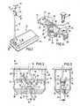
- a hanging lamp 10 with two suspension devices is suspended from the ceiling 11, only one suspension device 12 being shown. Both suspension devices grip at the front ends of the elongated lamp housing 13, specifically outside the area which is delimited by the lamp sockets provided in the interior of the lamp housing 13.
- a ceiling hook 14 is attached to the ceiling 11, in which the suspension bracket 15 is suspended.
- hanging type extends between the suspension bracket 15 and the housing holder 16 attached to the lamp housing 13, a tubular rod 17, through which a cable 18 for electrically connecting the lamp with a (not shown) ceiling connection in the vicinity of the hook 14 extends.
- the suspension bracket 15 has a flat upper mounting plate 19, under which a web 20 protruding downwards at right angles extends.
- Two arms 21 project downward from the web 20.
- the lower ends of the arms 21 are connected to one another by the retaining ring 22, the ring plane of which extends parallel to the plane of the mounting plate 19.
- the retaining ring 22 is provided with an internal thread 23 into which an external thread 24 (FIGS. 2 and 3) provided at the upper end of the rod 17 can be screwed.
- the horizontal web 20 forms, together with the arms 21 and the retaining ring 22, an eyelet 25 for inserting the hook 14.
- the upper limit of the eyelet 25 has the shape of an inverted V, the two flanks of which converge in the middle of the length of the holding bracket, so that the bracket 15 on the hook 14 is self-centering.
- the mounting plate 19 is provided in the central region of its length with two lateral recesses 26, the depth of which is so great that the width of the holding plate 19 is reduced to the width of the web 20 in the central region.
- the trapezoidal cutouts 26 serve to facilitate the insertion of the hook 14 into the eyelet 25 and, in the inserted state, to enable pendulum movements of the suspension bracket 15 with respect to the hook 14.
- Transversely elongated holes 27 are provided in the mounting plate 19 in order to be able to carry out the direct ceiling mounting of the suspension bracket 15 with screws.
- the elongated holes 27 are used to attach columnar buffer elements 28 made of rubber, which protrude from the holding plate 19. 2 extend into the vicinity of the ceiling 11 and serve to limit and dampen pendulum movements of the suspension bracket 15.
- Vertical bores 29 run through the mounting plate 19 and the web 20, into which transverse threaded bores 30 open in the region of the web 20. Clamping screws 31 are screwed into the threaded bores 30 in order to clamp a rope pulled through the bores 29.
- a groove 32 runs in the upper side of the mounting plate 19 and connects the upper ends of the bores 29 to one another.
- clamping legs 33 which are provided with corrugations on the outside, project downward. If a protective cap 34 made of plastic, which has a through opening 35 for the rod 17, is pushed onto the hanging bracket 15 from below, the clamping limbs 33 spread the protective cap 34 apart slightly, so that the protection cap is held clamped to the suspension bracket 15. The protective cap can be pushed onto the suspension bracket until its upper end abuts the ceiling 11. The clamping legs 33 hold the protective cap 34 regardless of how far this protective cap is pushed over the suspension bracket or how far the suspension bracket 15 dips into the protection cap.
- contact elements 36 in the form of screws screwed into threaded bores are provided on the web 20. These contact elements 36 can be connected to earth or earth lines in order to ground the suspension bracket and the electrically conductive parts connected to it.
- the suspension bracket described consists (with the exception of the screws inserted in it) from a one-piece metal part which can be produced, for example, by the die-casting process.
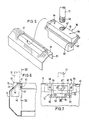
- the attached to the lower end of the rod 17 housing holder 16 consists of a metallic block 40 which is inserted from the inside into a cutout 41 of the end wall of the housing 13 and has an edge 42 which does not fit through the housing opening 41 and thus a support for forms the edge of the housing opening.
- the projection 46 of the block 16 projecting through the housing opening 41 contains a threaded bore 47 into which a thread 48 provided at the lower end of the rod 17 can be screwed.
- the block 40 At the lower end of the extension 46 there is a small projection 49 or an undercut which hooks on the edge of the housing opening 41.
- the block 40 At the block 40 is provided with protrusion 49 with two elastic buffers 50 which protrude slightly and press against an inner wall 51 of housing 13. The lamp holders (not shown) are also fastened to this inner wall 51.
- the elastic buffers 50 By means of the elastic buffers 50, the block 40 is pressed with its projection 49 outwards over the edge of the housing opening 41, so that it receives a hold on the housing 13 and cannot accidentally fall into the housing.
- the block 40 is therefore only loosely inserted from the inside into the housing 13 and clamped onto the housing wall.
- the block 40 is released by pressing this block in the direction of the wall 51, as a result of which the projection 49 is released from the edge of the housing opening 41, so that the block 40 can then be lowered into the interior of the housing. Conversely, the block 40 is assembled in the manner shown in FIG. 5 from the inside of the housing.
- a cavity 52 in the block 40 into which the through hole 47 opens and in which a clamping device 53 is attached in order to be able to clamp a cable 18 running through the through opening 47 to the block 40 for the purpose of strain relief.
- rope through bores 54 extend on both sides of the through opening 47, into which cross bores with clamping screws 55 open in the interior of the housing.
- the clamping screws 55 serve to fix the cable sections passed through the cable through-holes 54.
- the heads of the clamping screws 55 like the heads of the screws of the clamping device 53, face the interior of the housing, so that all the screws of the housing holder are accessible from the inside of the housing. Alignment or height adjustment can therefore take place with the housing holder 16 inserted into the luminaire housing, for example if the lower lamp cover is removed from the luminaire housing.
- FIGS. 1 to 7 While in the case of FIGS. 1 to 7 shown use of the suspension device rods 17 is used in Figs. 8 and 9 show a type of use in which the lamp is suspended from the suspension bracket 15 with a rope 60.
- There is a single rope 60 the two end regions of which are fixed to the block 40 with the clamping screws 55.
- the rope ends protrude from the lower end of the block 40 into the lamp housing 13.
- the rope through holes 54 in the housing holder 16 are at the same mutual distance as the holes 29 in the suspension bracket 15.
- rope openings 61 are provided in the bottom of the protective cap 34, which are also at a distance from the holes 29.
- the rope 60 thus leads from a rope through bore 54 into the protective cap 34, through a bore 29, then at the top of the mounting plate 15 in the groove 32 to the other bore 29 and from there through the protective cap 34 back to the housing holder 16.
- the clamping screws 31 in the suspension bracket 15 enable the cable 60 to be fixed in such a way that the lamp 10 is prevented from laterally sloping.
- the electrical cable is fastened with a strain relief part 62 to the retaining ring 22 of the suspension bracket 15.
- the strain relief part 62 consists of a threaded bushing which is screwed into the thread of the retaining ring 22 and a clamping device 63 in the form of a clamping screw for clamping the Has cable 18.
- the cable 18 leads down through the through opening 35 of the protective cap 34, protrudes through the through opening 47 of the housing holder 16 and is fixed in the housing holder 16 with the clamping device 53.
- the suspension bracket 15 with the mounting plate 19 is placed directly under the ceiling 11 and fastened to the ceiling with screws which pass through the holes 27.
- the protective cap 34 is pushed over the clamping legs 33, which in this case engage near the upper edge on the side wall of the protective cap 34.
- the suspension bracket 15, the protective cap 34 and the housing holder 16 can be used equally with both suspension types.
- Only the rod 17, the wire rope 60 and the strain relief part 62 are parts which are each optionally used in a particular type of suspension. These optional parts are relatively simple, so that their production does not cause great costs and there is no significant additional effort due to their non-use.
Landscapes
- Engineering & Computer Science (AREA)
- General Engineering & Computer Science (AREA)
- Non-Portable Lighting Devices Or Systems Thereof (AREA)
- Circuit Arrangements For Discharge Lamps (AREA)
- Load-Engaging Elements For Cranes (AREA)
- Fastening Of Light Sources Or Lamp Holders (AREA)
Priority Applications (1)
| Application Number | Priority Date | Filing Date | Title |
|---|---|---|---|
| AT8888101839T ATE105394T1 (de) | 1987-03-31 | 1988-02-09 | Aufhaengevorrichtung fuer haengeleuchten. |
Applications Claiming Priority (2)
| Application Number | Priority Date | Filing Date | Title |
|---|---|---|---|
| DE19873710609 DE3710609A1 (de) | 1987-03-31 | 1987-03-31 | Aufhaengevorrichtung fuer haengeleuchten |
| DE3710609 | 1987-03-31 |
Publications (3)
| Publication Number | Publication Date |
|---|---|
| EP0284740A2 true EP0284740A2 (fr) | 1988-10-05 |
| EP0284740A3 EP0284740A3 (en) | 1989-12-27 |
| EP0284740B1 EP0284740B1 (fr) | 1994-05-04 |
Family
ID=6324416
Family Applications (1)
| Application Number | Title | Priority Date | Filing Date |
|---|---|---|---|
| EP88101839A Expired - Lifetime EP0284740B1 (fr) | 1987-03-31 | 1988-02-09 | Dispositif de suspension pour lampes |
Country Status (3)
| Country | Link |
|---|---|
| EP (1) | EP0284740B1 (fr) |
| AT (1) | ATE105394T1 (fr) |
| DE (2) | DE3710609A1 (fr) |
Cited By (3)
| Publication number | Priority date | Publication date | Assignee | Title |
|---|---|---|---|---|
| EP0579971A1 (fr) * | 1992-06-25 | 1994-01-26 | Mid-America Building Products Corporation | Ensemble de montage en plastique pour un mur de bâtiment |
| EP0942229A1 (fr) * | 1998-03-10 | 1999-09-15 | Koninklijke Philips Electronics N.V. | Suspension de luminaire d'intérieur avec un cache pour cacher le point de fixation |
| WO2003027570A1 (fr) * | 2001-09-26 | 2003-04-03 | Ivalo Lighting Inc. | Appareil de montage de dispositif d'eclairage |
Families Citing this family (3)
| Publication number | Priority date | Publication date | Assignee | Title |
|---|---|---|---|---|
| US7347582B1 (en) | 2005-06-15 | 2008-03-25 | Dorcy International, Inc. | Invertible light source |
| DE202017103973U1 (de) | 2017-07-04 | 2017-08-17 | Christian Seltmann | Aufhängevorrichtung zur Deckenbefestigung einer Hängeleuchte |
| DE102019128713B4 (de) * | 2019-10-24 | 2022-06-15 | Bernd König | Deckenleuchtenhalterung und Deckenleuchtenanordnung |
Family Cites Families (9)
| Publication number | Priority date | Publication date | Assignee | Title |
|---|---|---|---|---|
| US1518768A (en) * | 1922-08-10 | 1924-12-09 | Albert F Anderson | Electric-fixture hanger |
| US1680078A (en) * | 1925-03-18 | 1928-08-07 | Miller Co | Lighting fixture |
| FR43193E (fr) * | 1932-11-25 | 1934-03-09 | Lampes Sa | Dispositif pour la fixation d'une monture sur le col d'un appareil d'éclairage |
| DE802262C (de) * | 1949-11-08 | 1951-02-08 | Schanzenbach & Co G M B H G | Pendeleinrichtung fuer Leuchtstofflampenreihen |
| US2739780A (en) * | 1954-01-11 | 1956-03-27 | Fluorescent Fixtures Of Califo | Fixture hanger assembly |
| US2990153A (en) * | 1954-12-13 | 1961-06-27 | Wolar Isidore | Hangers for cord supported fixtures |
| FR1542063A (fr) * | 1966-11-03 | Trilux Lenze Gmbh & Co Kg | Dispositif pour la fixation d'un appareil d'éclairage à un plafond ou à une paroi | |
| DE2815006A1 (de) * | 1978-04-07 | 1979-10-18 | Zeiss Ikon Ag | Leuchtentragschienensystem |
| DE8518629U1 (de) * | 1985-06-27 | 1986-10-30 | Philips Patentverwaltung Gmbh, 2000 Hamburg | Vorrichtung zum Aufhängen eines Leuchtentragseiles an einer Decke |
-
1987
- 1987-03-31 DE DE19873710609 patent/DE3710609A1/de not_active Ceased
-
1988
- 1988-02-09 DE DE3889375T patent/DE3889375D1/de not_active Expired - Fee Related
- 1988-02-09 EP EP88101839A patent/EP0284740B1/fr not_active Expired - Lifetime
- 1988-02-09 AT AT8888101839T patent/ATE105394T1/de not_active IP Right Cessation
Cited By (3)
| Publication number | Priority date | Publication date | Assignee | Title |
|---|---|---|---|---|
| EP0579971A1 (fr) * | 1992-06-25 | 1994-01-26 | Mid-America Building Products Corporation | Ensemble de montage en plastique pour un mur de bâtiment |
| EP0942229A1 (fr) * | 1998-03-10 | 1999-09-15 | Koninklijke Philips Electronics N.V. | Suspension de luminaire d'intérieur avec un cache pour cacher le point de fixation |
| WO2003027570A1 (fr) * | 2001-09-26 | 2003-04-03 | Ivalo Lighting Inc. | Appareil de montage de dispositif d'eclairage |
Also Published As
| Publication number | Publication date |
|---|---|
| EP0284740A3 (en) | 1989-12-27 |
| EP0284740B1 (fr) | 1994-05-04 |
| ATE105394T1 (de) | 1994-05-15 |
| DE3710609A1 (de) | 1988-10-20 |
| DE3889375D1 (de) | 1994-06-09 |
Similar Documents
| Publication | Publication Date | Title |
|---|---|---|
| CH667579A5 (de) | Trageinrichtung mit stufenlos verstellbaren auslegern. | |
| EP0284740B1 (fr) | Dispositif de suspension pour lampes | |
| DE2123097A1 (de) | Werkzeughalter für ein Kabelspleißgerät | |
| AT403839B (de) | Halter insbesondere für rohre, kabelstränge und hohlleiter | |
| DE3214596C2 (de) | Aufhängebügel | |
| DE102018105970B4 (de) | Variable Deckenbefestigung | |
| DE9205108U1 (de) | Halterung zur Aufnahme von Gegenständen an Gitterflächen | |
| DE3539169A1 (de) | Vorrichtung zur lagerung und schaustellung von warenpaeckchen | |
| DE7522285U (de) | Einrichtung zur lösbaren Verbindung zweier Bauteile | |
| DE29901397U1 (de) | Längliche, im Querschnittsprofil linsenartige Pendel- oder Anbauleuchte | |
| DE4413124A1 (de) | Vorrichtung zum Halten und Führen von Kabeln und Schläuchen in Schaltschränken | |
| EP0867657A2 (fr) | Lampe | |
| DE4010416A1 (de) | Aufhaengevorrichtung | |
| DE3008307A1 (de) | Befestigungsbeschlag zur formschluessigen verbindung mindestens zweier mit hinterschneidungen o.dgl. versehener profile | |
| AT17365U1 (de) | Befestigungsvorrichtung zur Befestigung einer Leuchte | |
| DE3340644A1 (de) | Scharnier, insbesondere fuer ausstellstangen von treibstangenbeschlaegen fuer fenster oder dergleichen | |
| DE69907559T2 (de) | Verankerungsvorrichtung für Kronleuchter | |
| DE9216604U1 (de) | Aufhängevorrichtung zum Aufhängen von Gegenständen, insbesondere Bilderhaltern an einer Schnur, einem Drahtseil o.dgl. | |
| DE9101353U1 (de) | Rohraufhänger | |
| DE3705027C2 (fr) | ||
| DE7720666U1 (de) | Halteschelle fuer rohre, kabel u.dgl. | |
| DE2812489B2 (de) | Aufhängevorrichtung für großflächige Deckenleuchten | |
| DE29501156U1 (de) | Leuchtenanordnung | |
| DE1191882B (de) | Befestigungsvorrichtung fuer elektrische Installationsgeraete, insbesondere D-Sicherungssockel auf Tragschienen | |
| DE1913393A1 (de) | Aufhaengevorrichtung fuer Beleuchtungskoerper |
Legal Events
| Date | Code | Title | Description |
|---|---|---|---|
| PUAI | Public reference made under article 153(3) epc to a published international application that has entered the european phase |
Free format text: ORIGINAL CODE: 0009012 |
|
| AK | Designated contracting states |
Kind code of ref document: A2 Designated state(s): AT DE FR GB IT NL |
|
| PUAL | Search report despatched |
Free format text: ORIGINAL CODE: 0009013 |
|
| AK | Designated contracting states |
Kind code of ref document: A3 Designated state(s): AT DE FR GB IT NL |
|
| 17P | Request for examination filed |
Effective date: 19900518 |
|
| 17Q | First examination report despatched |
Effective date: 19921211 |
|
| GRAA | (expected) grant |
Free format text: ORIGINAL CODE: 0009210 |
|
| AK | Designated contracting states |
Kind code of ref document: B1 Designated state(s): AT DE FR GB IT NL |
|
| PG25 | Lapsed in a contracting state [announced via postgrant information from national office to epo] |
Ref country code: IT Free format text: LAPSE BECAUSE OF FAILURE TO SUBMIT A TRANSLATION OF THE DESCRIPTION OR TO PAY THE FEE WITHIN THE PRESCRIBED TIME-LIMIT;WARNING: LAPSES OF ITALIAN PATENTS WITH EFFECTIVE DATE BEFORE 2007 MAY HAVE OCCURRED AT ANY TIME BEFORE 2007. THE CORRECT EFFECTIVE DATE MAY BE DIFFERENT FROM THE ONE RECORDED. Effective date: 19940504 Ref country code: NL Effective date: 19940504 Ref country code: GB Effective date: 19940504 Ref country code: FR Effective date: 19940504 |
|
| REF | Corresponds to: |
Ref document number: 105394 Country of ref document: AT Date of ref document: 19940515 Kind code of ref document: T |
|
| REF | Corresponds to: |
Ref document number: 3889375 Country of ref document: DE Date of ref document: 19940609 |
|
| EN | Fr: translation not filed | ||
| NLV1 | Nl: lapsed or annulled due to failure to fulfill the requirements of art. 29p and 29m of the patents act | ||
| GBV | Gb: ep patent (uk) treated as always having been void in accordance with gb section 77(7)/1977 [no translation filed] |
Effective date: 19940504 |
|
| PG25 | Lapsed in a contracting state [announced via postgrant information from national office to epo] |
Ref country code: AT Effective date: 19950209 |
|
| PLBE | No opposition filed within time limit |
Free format text: ORIGINAL CODE: 0009261 |
|
| STAA | Information on the status of an ep patent application or granted ep patent |
Free format text: STATUS: NO OPPOSITION FILED WITHIN TIME LIMIT |
|
| 26N | No opposition filed | ||
| PG25 | Lapsed in a contracting state [announced via postgrant information from national office to epo] |
Ref country code: DE Effective date: 19951101 |