EP0284902A2 - Procédé et dispositif pour joindre des tôles minces mises les unes sur les autres - Google Patents
Procédé et dispositif pour joindre des tôles minces mises les unes sur les autres Download PDFInfo
- Publication number
- EP0284902A2 EP0284902A2 EP88104218A EP88104218A EP0284902A2 EP 0284902 A2 EP0284902 A2 EP 0284902A2 EP 88104218 A EP88104218 A EP 88104218A EP 88104218 A EP88104218 A EP 88104218A EP 0284902 A2 EP0284902 A2 EP 0284902A2
- Authority
- EP
- European Patent Office
- Prior art keywords
- die
- plate
- stamp
- leveling
- plates
- Prior art date
- Legal status (The legal status is an assumption and is not a legal conclusion. Google has not performed a legal analysis and makes no representation as to the accuracy of the status listed.)
- Granted
Links
Images

Classifications
-
- B—PERFORMING OPERATIONS; TRANSPORTING
- B32—LAYERED PRODUCTS
- B32B—LAYERED PRODUCTS, i.e. PRODUCTS BUILT-UP OF STRATA OF FLAT OR NON-FLAT, e.g. CELLULAR OR HONEYCOMB, FORM
- B32B37/00—Methods or apparatus for laminating, e.g. by curing or by ultrasonic bonding
-
- B—PERFORMING OPERATIONS; TRANSPORTING
- B21—MECHANICAL METAL-WORKING WITHOUT ESSENTIALLY REMOVING MATERIAL; PUNCHING METAL
- B21D—WORKING OR PROCESSING OF SHEET METAL OR METAL TUBES, RODS OR PROFILES WITHOUT ESSENTIALLY REMOVING MATERIAL; PUNCHING METAL
- B21D39/00—Application of procedures in order to connect objects or parts, e.g. coating with sheet metal otherwise than by plating; Tube expanders
- B21D39/03—Application of procedures in order to connect objects or parts, e.g. coating with sheet metal otherwise than by plating; Tube expanders of sheet metal otherwise than by folding
- B21D39/031—Joining superposed plates by locally deforming without slitting or piercing
-
- B—PERFORMING OPERATIONS; TRANSPORTING
- B21—MECHANICAL METAL-WORKING WITHOUT ESSENTIALLY REMOVING MATERIAL; PUNCHING METAL
- B21D—WORKING OR PROCESSING OF SHEET METAL OR METAL TUBES, RODS OR PROFILES WITHOUT ESSENTIALLY REMOVING MATERIAL; PUNCHING METAL
- B21D39/00—Application of procedures in order to connect objects or parts, e.g. coating with sheet metal otherwise than by plating; Tube expanders
- B21D39/03—Application of procedures in order to connect objects or parts, e.g. coating with sheet metal otherwise than by plating; Tube expanders of sheet metal otherwise than by folding
-
- Y—GENERAL TAGGING OF NEW TECHNOLOGICAL DEVELOPMENTS; GENERAL TAGGING OF CROSS-SECTIONAL TECHNOLOGIES SPANNING OVER SEVERAL SECTIONS OF THE IPC; TECHNICAL SUBJECTS COVERED BY FORMER USPC CROSS-REFERENCE ART COLLECTIONS [XRACs] AND DIGESTS
- Y10—TECHNICAL SUBJECTS COVERED BY FORMER USPC
- Y10T—TECHNICAL SUBJECTS COVERED BY FORMER US CLASSIFICATION
- Y10T29/00—Metal working
- Y10T29/49—Method of mechanical manufacture
- Y10T29/49826—Assembling or joining
- Y10T29/49908—Joining by deforming
- Y10T29/49915—Overedge assembling of seated part
-
- Y—GENERAL TAGGING OF NEW TECHNOLOGICAL DEVELOPMENTS; GENERAL TAGGING OF CROSS-SECTIONAL TECHNOLOGIES SPANNING OVER SEVERAL SECTIONS OF THE IPC; TECHNICAL SUBJECTS COVERED BY FORMER USPC CROSS-REFERENCE ART COLLECTIONS [XRACs] AND DIGESTS
- Y10—TECHNICAL SUBJECTS COVERED BY FORMER USPC
- Y10T—TECHNICAL SUBJECTS COVERED BY FORMER US CLASSIFICATION
- Y10T29/00—Metal working
- Y10T29/49—Method of mechanical manufacture
- Y10T29/49826—Assembling or joining
- Y10T29/49908—Joining by deforming
- Y10T29/49936—Surface interlocking
-
- Y—GENERAL TAGGING OF NEW TECHNOLOGICAL DEVELOPMENTS; GENERAL TAGGING OF CROSS-SECTIONAL TECHNOLOGIES SPANNING OVER SEVERAL SECTIONS OF THE IPC; TECHNICAL SUBJECTS COVERED BY FORMER USPC CROSS-REFERENCE ART COLLECTIONS [XRACs] AND DIGESTS
- Y10—TECHNICAL SUBJECTS COVERED BY FORMER USPC
- Y10T—TECHNICAL SUBJECTS COVERED BY FORMER US CLASSIFICATION
- Y10T29/00—Metal working
- Y10T29/49—Method of mechanical manufacture
- Y10T29/49826—Assembling or joining
- Y10T29/49908—Joining by deforming
- Y10T29/49938—Radially expanding part in cavity, aperture, or hollow body
-
- Y—GENERAL TAGGING OF NEW TECHNOLOGICAL DEVELOPMENTS; GENERAL TAGGING OF CROSS-SECTIONAL TECHNOLOGIES SPANNING OVER SEVERAL SECTIONS OF THE IPC; TECHNICAL SUBJECTS COVERED BY FORMER USPC CROSS-REFERENCE ART COLLECTIONS [XRACs] AND DIGESTS
- Y10—TECHNICAL SUBJECTS COVERED BY FORMER USPC
- Y10T—TECHNICAL SUBJECTS COVERED BY FORMER US CLASSIFICATION
- Y10T403/00—Joints and connections
- Y10T403/49—Member deformed in situ
- Y10T403/4991—Both members deformed
Definitions
- the invention is based on a method for connecting superimposed thin plates (in particular sheets) according to the type of the main claim and the type of claim 4 and claim 7.
- connection technology has a wide range of applications, since it does not require any additional auxiliary parts, such as rivets, screws and the like, without the connection quality being therefore poorer.
- Such connections are not only subject to considerable tensile forces, but also shear forces and, in addition to the frictional connection, always have a positive connection at the connection point between the plates, although despite all the advantages there remains a disadvantage that the sheet metal projection formed by the joining element protrudes from the plate plane, so that this type of connection technology cannot be used everywhere. Other objects can get caught on these sheet metal warts or they represent undesired elevations, for example on parts to be painted.
- a known method of the generic type (US Pat. No. 3,934,327) produces punching cams in which a crushing operation follows after a deep-drawing and punching process, the plate piece closer to the plates being widened by squeezing and engaging behind the plates with its edges (clinching ). So that the sheet metal projection protrudes as little as possible from the plane of the plate, a depression is embossed into the plates by means of additional pressing tools, within which the punching cam is then formed, so that its joining parts protrude only insignificantly from this depression.
- the disadvantage is that there are now elevations on both sides of the plates to be connected, so that the problem mentioned at the outset is not resolved, but only relocated.
- the inventive method according to the characterizing features of the main claim has the advantage that after joining the plates no protruding parts from the plate level, such as sheet metal warts, are present, the remaining blind openings on the plate surface on the the stamp was used smaller than in the known methods, but are also of minor importance.
- this connection technology can thus be used to a much greater extent without being associated with any significant increase in price.
- An essential and, above all, surprising advantage of the invention is that the additional material deformation in the joining element leads to a considerable increase in strength, particularly with regard to shear, which can be up to 100% compared to an unplaned connection. Dynamic strength is also improved.
- the device according to the invention with the characterizing features of claim 4 draws on experience such as has long been available in this connection technology, namely on two-part tools with a die, the bottom of which is displaceable and serves on the one hand as a die base and on the other hand serves as a stamping base during the leveling process.
- the actual stamp which performs its stamping function at the start of the joining process and then acts as a calibration stamp by gently retracting it during the leveling process.
- the guide part surrounding the actual stamp for example a bushing, can already be moved onto the plates at the beginning of the deep-drawing or punching process in order to clamp them together with the die tool.
- this stamp is resiliently mounted in the guide part in the direction of force, the flexibility only having an effect on the leveling force, so that during the deep-drawing and also crushing process the stamp remains in its position relative to the guide part and only, when the strong leveling force occurs from the die side, gives way to provide enough space for the squeezed material.
- the device with the characterizing features of claim 7 has the advantage over the known devices that a relatively small additional tool effort is required and that simple tools can be used, which affects above all the life of these tools.
- a roller device can also be used for the leveling, in particular with a pair of rollers, one roller of which has a smooth surface, while the other roller has calibration mandrels which engage in the blind openings already created by the previous joining process.
- the first embodiment is shown as a tool example, only the actual manufacturing tool in five different working positions and the plates to be connected are shown.
- the completeness of the invention also includes the pressing device, which can be designed in a wide variety of ways and by means of which the tool must be actuated in order to carry out the connection according to the invention.
- the tool consists of a punch 1 of a die 2 and an anvil 3, which is displaceable relative to the die 2.
- the plates to be connected are present between the punch 1 and the die 2, a lower plate 4 and an upper plate 5.
- These plates are mostly sheets, although more than two such sheets can of course also be connected to one another.
- a bushing 6 (guide part) is arranged around the stamp 1 and can be displaced relative to the stamp 1.
- a correspondingly changeable length of the working pin 7 protrudes from the socket 6.
- the upper plate 5 faces the shoulder 8 of the socket 6 and the end face 9 of the working pin 7.
- the first part of the working process namely the deep-drawing, has ended, in which the working pin 7 has deep-drawn the plate portions 10 and 11 of the two plates 4 and 5 upstream of its free end face 9 into a pocket opening.
- the die 1 assumes its end position in which the deep-drawn plate portions 10 and 11 have already been squeezed. In this position, the shoulder 8 lies against the surface of the plate 5.
- the plate portions opposite the end face 9 are strongly pressed together by the resistance of the anvil 3 and the delimiting die 2, the material being displaced radially outwards. Due to the squeezing effect, the deep-drawn plate portions were radially expanded to a squeeze part shown horizontally here that it reaches behind the deep-drawing opening 14 of the lower plate 4.
- a form-fitting, extremely strong connection is achieved by flowing the plate material into one another.
- the tool assumes the end position after a leveling operation of the two plate parts 10 and 11, that is to say the entire machining operation, in which the anvil 3 has been pushed up into the plane of the plates 4 and 5 and thereby the deep-drawn parts 10, 11 displaced into the plate level.
- the material displaced thereby fills the previously formed cavity 15, the form stamp 1 functioning as a calibration stamp and the bushing 6 as a resistance bearing.
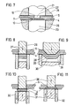
- FIG. 6 shows an embodiment of the bushing 6 and the dozer 7, in which the dozer 7 is supported by a collar 16 on an elastic material 17, for example a spring, and its stroke is limited by a stop 18.
- This elastic material 17 is designed so that it does not give way during the deep-drawing and squeezing process, but only during the leveling process, that is to say when the anvil 3 is moved in the direction of plates 4, 5. As a result, an extra die 7 is pressed inside the bush 6 Tool saved.
- FIG. 7 shows a second exemplary embodiment in which the leveling process is carried out at a separate work station.
- the steps shown in FIGS. 1 to 3 are carried out at the first work station, while here only the leveling process shown in FIG. 5 is carried out for the separate work station.
- the diameter of the leveling ram 23 is in any case so large that it covers the bleck wart formed by the joining or the drawn plate parts 10 and 11.
- FIG. 8 to 11 show the third exemplary embodiment in which a punching cam is subsequently leveled.
- a stamping and pressing stamp 26 which can be moved back and forth by appropriate devices, cuts through the plates 5 and 4 at the points 27 and leaves lateral sections 28 which are only deep-drawn.
- 8 shows a cross section at which the interfaces can be seen
- FIG. 9 shows a section rotated by 90 ° with respect to FIG. 8, from which the deep-drawn connection can be seen.
- Fig. 10 it is shown how the pressed-out sheet metal parts 29 and 30 are squeezed by moving an anvil 31 upwards by the punching and pressing punch 26 remaining. As a result, at least the sheet metal section becomes at the interfaces 29 expands and engages behind the lower plate 4. In order to allow a flow of material, the die 32 was moved slightly downwards for this squeezing process.
- Fig. 11 shows the leveling process again, in which the punching and pressing die 26 has moved slightly upwards, in order to again create a space for receiving crushed material and in which the anvil 31 and the die 32 now form a common press die up to the plane of the plates 4 and 5 are shifted.
Landscapes
- Engineering & Computer Science (AREA)
- Mechanical Engineering (AREA)
- Shaping Metal By Deep-Drawing, Or The Like (AREA)
- Connection Of Plates (AREA)
- Perforating, Stamping-Out Or Severing By Means Other Than Cutting (AREA)
- Lining Or Joining Of Plastics Or The Like (AREA)
- Press Drives And Press Lines (AREA)
- Coupling Device And Connection With Printed Circuit (AREA)
- Non-Reversible Transmitting Devices (AREA)
- Arc Welding In General (AREA)
- Forging (AREA)
- Pressure Welding/Diffusion-Bonding (AREA)
Priority Applications (1)
| Application Number | Priority Date | Filing Date | Title |
|---|---|---|---|
| AT88104218T ATE91654T1 (de) | 1987-04-01 | 1988-03-17 | Verfahren und vorrichtung zum verbinden aufeinanderliegender duenner platten. |
Applications Claiming Priority (2)
| Application Number | Priority Date | Filing Date | Title |
|---|---|---|---|
| DE19873710929 DE3710929A1 (de) | 1987-04-01 | 1987-04-01 | Verfahren und vorrichtung zum verbinden aufeinanderliegender duenner platten |
| DE3710929 | 1987-04-01 |
Publications (3)
| Publication Number | Publication Date |
|---|---|
| EP0284902A2 true EP0284902A2 (fr) | 1988-10-05 |
| EP0284902A3 EP0284902A3 (en) | 1990-06-06 |
| EP0284902B1 EP0284902B1 (fr) | 1993-07-21 |
Family
ID=6324608
Family Applications (1)
| Application Number | Title | Priority Date | Filing Date |
|---|---|---|---|
| EP88104218A Revoked EP0284902B1 (fr) | 1987-04-01 | 1988-03-17 | Procédé et dispositif pour joindre des tôles minces mises les unes sur les autres |
Country Status (9)
| Country | Link |
|---|---|
| US (1) | US4831711A (fr) |
| EP (1) | EP0284902B1 (fr) |
| JP (1) | JPS63256231A (fr) |
| KR (1) | KR930012252B1 (fr) |
| AT (1) | ATE91654T1 (fr) |
| AU (1) | AU598355B2 (fr) |
| BR (1) | BR8801516A (fr) |
| DE (2) | DE3710929A1 (fr) |
| ES (1) | ES2041718T3 (fr) |
Cited By (7)
| Publication number | Priority date | Publication date | Assignee | Title |
|---|---|---|---|---|
| DE4139347A1 (de) * | 1991-11-29 | 1993-06-03 | Sta Co Mettallerzeugnisse Gmbh | Druckfuegespannvorrichtung |
| EP0546270A1 (fr) * | 1991-11-13 | 1993-06-16 | ECKOLD GmbH & Co. KG | Procédé pour la transformation locale de matière fragile |
| EP0601281A1 (fr) * | 1992-12-05 | 1994-06-15 | ECKOLD GmbH & Co. KG | Procédé pour joindre des tôles recouvrantes et jeu d'outil pour la fabrication d'assemblage |
| DE4432639A1 (de) * | 1994-09-14 | 1996-03-28 | Meinig Metu System | Verfahren und Vorrichtung zum Verbinden zweier oder mehrerer Blechlagen |
| DE10245604A1 (de) * | 2002-09-30 | 2004-04-15 | Fraunhofer-Gesellschaft zur Förderung der angewandten Forschung e.V. | Verfahren und Vorrichtung zum dauerhaften Verbinden von einander überlappenden, plattenförmigen Bauteilen |
| DE10250342A1 (de) * | 2002-10-29 | 2004-05-19 | Daimlerchrysler Ag | Fügeverfahren und Fügevorrichtung zum Verbinden von überlappend angeordneten Fügeteilen |
| EP2921241A1 (fr) * | 2014-03-18 | 2015-09-23 | BTM Corporation | Appareil de clinchage et procédé pour sa fabrication |
Families Citing this family (43)
| Publication number | Priority date | Publication date | Assignee | Title |
|---|---|---|---|---|
| SE8800407D0 (sv) * | 1988-02-05 | 1988-02-05 | Cerac Sa | A method for joining two or several overlaying sheet formed members together, metal or non-metal, and an apparatus for carrying out said method |
| DE3934743A1 (de) * | 1989-10-18 | 1991-04-25 | Eckold Vorrichtung | Verfahren zum verbinden zweier bauteile |
| DE4012206C2 (de) * | 1990-04-14 | 1994-02-17 | Porsche Ag | Verbundelement |
| US5432989A (en) * | 1992-10-27 | 1995-07-18 | Archer Manufacturing Corporation | Apparatus and method for joining sheet material |
| JP2583201B2 (ja) * | 1994-08-05 | 1997-02-19 | 株式会社エナミ精機 | 金属板間の接合構造 |
| GB9616849D0 (en) * | 1996-08-10 | 1996-09-25 | T & N Technology Ltd | Forming a composite panel |
| US5939212A (en) * | 1997-06-09 | 1999-08-17 | Atd Corporation | Flexible corrugated multilayer metal foil shields and method of making |
| US6047511A (en) * | 1998-03-04 | 2000-04-11 | Usg Interiors, Inc. | Grid tee with integrally stitched web |
| TW556074B (en) * | 1998-12-15 | 2003-10-01 | Foxconn Prec Components Co Ltd | Heat sink and the manufacturing method thereof |
| US6231944B1 (en) | 1999-07-27 | 2001-05-15 | Lydall, Inc. | Method for producing a thermal, acoustical and/or vibrational abatement shield and shield produced thereby |
| US6205641B1 (en) * | 1999-09-29 | 2001-03-27 | Lucent Technologies, Inc. | Anvil assembly for a press for assembling a fastener into a workpiece |
| US6345438B1 (en) * | 2000-06-08 | 2002-02-12 | Homac Manufacturing Company | Method for making bus and post electrical connector using locking pins |
| US6493907B2 (en) | 2001-01-12 | 2002-12-17 | Honeywell International Inc. | Wire terminal fastener and method |
| JP2004520941A (ja) * | 2001-05-11 | 2004-07-15 | トックス・プレッソテヒニック・ゲゼルシャフト・ミト・ベシュレンクテル・ハフツング・ウント・コンパニー・コマンディトゲゼルシャフト | 板を機械的に結合するための工具 |
| DE10130726C2 (de) * | 2001-06-21 | 2003-07-03 | Zebras Zentrum Fuer Entwicklun | Verfahren und Einrichtung zur Herstellung einer Verbindung zwischen sich überlappenden plattenförmigen Bauteilen |
| DE10130723C2 (de) * | 2001-06-21 | 2003-10-09 | Zebras Zentrum Fuer Entwicklun | Verfahren und Einrichtung zur Herstellung einer Kaltpressschweißverbindung zwischen sich überlappenden plattenförmigen Bauteilen |
| WO2005078344A1 (fr) * | 2004-02-05 | 2005-08-25 | Beckett Gas, Inc. | Bruleur |
| JP4148152B2 (ja) * | 2004-02-16 | 2008-09-10 | マツダ株式会社 | 摩擦点接合構造 |
| BRPI0609143A2 (pt) | 2005-03-17 | 2011-09-13 | Ind Origami Llc | folha de material para a formação de uma estrutura estrutural tridimensional, viga oca e armação de exoesqueleto |
| RU2308344C2 (ru) * | 2005-10-26 | 2007-10-20 | Мемжанов Николай Османович | Способ соединения пакета деталей и силовая точка соединения пакета деталей |
| KR20080078915A (ko) * | 2005-12-22 | 2008-08-28 | 인더스트리얼 오리가미, 인크. | 평면 시트의 결합 방법 및 그 시트 |
| US7479600B2 (en) * | 2006-06-15 | 2009-01-20 | Group Dekko, Inc. | Electrical bus and method for forming an electrical bus |
| EP2079554A2 (fr) | 2006-10-26 | 2009-07-22 | Industrial Origami, Inc. | Procédé de transformation de matériau en feuille à deux dimensions en structure à trois dimensions |
| US8202628B2 (en) * | 2006-12-08 | 2012-06-19 | Musashi Seimitsu Kogyo Kabushiki Kaisha | Fusion-bonded product having high-strength part and manufacturing method thereof |
| EP2118553A4 (fr) | 2007-02-09 | 2014-04-16 | Ind Origami Inc | Structure tridimensionnelle portant une charge |
| AU2008215090B2 (en) * | 2007-02-13 | 2013-01-10 | Inventio Ag | Method and tool for clinching thick sheet metal, and use of the tool |
| JP2009026842A (ja) * | 2007-07-18 | 2009-02-05 | Isesaki Homing:Kk | 金属板連結固定方法、基板支持具、基板支持具付きレール、基板セット具 |
| US8757558B2 (en) * | 2007-12-17 | 2014-06-24 | Mp Husky, Llc | Cable tray |
| WO2009110298A1 (fr) * | 2008-02-17 | 2009-09-11 | Mori Shohei | Procédé, élément et dispositif de reliure du papier, et produit en papier en rapport avec l'invention |
| US7762034B2 (en) * | 2008-09-26 | 2010-07-27 | Chicago Metallic Corporation | Rotary stitch for joining sheet metal stock |
| US8024848B2 (en) * | 2008-10-08 | 2011-09-27 | GM Global Technology Operations LLC | Double-action clinching method |
| JP5287432B2 (ja) * | 2009-03-31 | 2013-09-11 | トヨタ車体株式会社 | 多段プレス装置及びそれを用いた被成形体の成形方法 |
| DE202009007835U1 (de) | 2009-06-03 | 2009-11-26 | Technische Universität Chemnitz | Hybrider Werkstoffverbund aus mehreren Fügepartnern |
| DE102009023717B4 (de) * | 2009-06-03 | 2014-05-22 | Technische Universität Chemnitz | Verfahren und Vorrichtung zur Herstellunq eines hybriden Werkstoffverbundes aus mehreren Füqepartnern und damit hergestellter hybrider Werkstoffverbund |
| EP2329905B1 (fr) * | 2009-12-03 | 2012-05-30 | Helmholtz-Zentrum Geesthacht Zentrum für Material- und Küstenforschung GmbH | Procédé pour assembler des pièces métalliques et plastiques |
| KR101180942B1 (ko) * | 2009-12-04 | 2012-09-07 | 현대자동차주식회사 | 서스펜션 암 |
| DE202011000731U1 (de) | 2011-03-30 | 2011-06-01 | Schmitz Cargobull AG, 48341 | Profilträger für ein Fahrzeugchassis und Nutzfahrzeugchassis mit einem solchen Profilträger |
| US8528187B2 (en) * | 2011-06-17 | 2013-09-10 | Gm Global Technology Operation Llc | Method and apparatus for joining multiple components |
| US8936164B2 (en) * | 2012-07-06 | 2015-01-20 | Industrial Origami, Inc. | Solar panel rack |
| DE102013008323A1 (de) * | 2013-05-08 | 2014-11-13 | Westfalia-Automotive Gmbh | Trägeranordnung für eine Anhängekupplung oder einen Lastenträger mit Steckzapfen |
| JP6161198B2 (ja) * | 2013-08-29 | 2017-07-12 | 株式会社Subaru | 異材接合方法 |
| DE102013020676B4 (de) | 2013-12-06 | 2023-03-02 | Daimler Truck AG | Lagerungseinheit für eine Fahrerhauslagerung eines Lastkraftwagens |
| USD1009309S1 (en) | 2020-04-21 | 2023-12-26 | Rockwool A/S | Grid tee for suspended ceiling |
Citations (2)
| Publication number | Priority date | Publication date | Assignee | Title |
|---|---|---|---|---|
| US3934327A (en) | 1974-08-16 | 1976-01-27 | Hafner Otto P | Method of interlocking overlapping sheet material |
| DE3532900A1 (de) | 1985-09-14 | 1987-03-26 | Eugen Rapp | Verfahren und vorrichtung zum verbinden duenner platten |
Family Cites Families (16)
| Publication number | Priority date | Publication date | Assignee | Title |
|---|---|---|---|---|
| US2122557A (en) * | 1936-08-14 | 1938-07-05 | Canter Morris | Method and apparatus for applying metallic seals |
| US2254558A (en) * | 1938-10-10 | 1941-09-02 | Ivan A Williams | Fastening element and method of making same |
| NL133141C (fr) * | 1964-05-20 | |||
| DE1652624A1 (de) * | 1968-03-14 | 1971-09-16 | Fraze Ermal C | Verfahren zur Herstellung eines Nietes und Werkzeugeinrichtung zur Ausfuehrung des Verfahrens |
| US3771216A (en) * | 1971-10-27 | 1973-11-13 | Johnson Die & Eng Co | Method and tooling for extruding a closed end rivet |
| JPS5659540A (en) * | 1979-10-19 | 1981-05-23 | Toshiba Corp | Joining device of plate material |
| JPS56114536A (en) * | 1980-02-13 | 1981-09-09 | Toshiba Corp | Joining device of sheet material |
| US4757609A (en) * | 1980-09-08 | 1988-07-19 | Btm Corporation | Apparatus for joining sheet material |
| JPS57195541A (en) * | 1981-05-29 | 1982-12-01 | Toshiba Corp | Joining method for plates |
| JPS58188522A (ja) * | 1982-04-30 | 1983-11-04 | Mitsubishi Electric Corp | 重ね合わせた金属板の固着方法 |
| US4531279A (en) * | 1982-08-23 | 1985-07-30 | Robertshaw Controls Company | Method of making a leakproof joint |
| US4601090A (en) * | 1982-08-23 | 1986-07-22 | Robertshaw Controls Company | Leakproof joint construction and apparatus for making the same |
| JPS61249635A (ja) * | 1985-04-26 | 1986-11-06 | Enami Seiki:Kk | 板状部材の接合方法 |
| EP0215449B1 (fr) * | 1985-09-14 | 1991-05-22 | RAPP, Eugen | Procédé et dispositif pour assembler des plaques minces |
| DE3532899A1 (de) * | 1985-09-14 | 1987-03-26 | Eugen Rapp | Verfahren und vorrichtung zum verbinden von platten durch stanznocken |
| JP3159061B2 (ja) * | 1996-06-21 | 2001-04-23 | 松下電工株式会社 | 金属箔貼り積層板の製造方法 |
-
1987
- 1987-04-01 DE DE19873710929 patent/DE3710929A1/de active Granted
-
1988
- 1988-03-17 DE DE8888104218T patent/DE3882407D1/de not_active Expired - Lifetime
- 1988-03-17 AT AT88104218T patent/ATE91654T1/de not_active IP Right Cessation
- 1988-03-17 ES ES198888104218T patent/ES2041718T3/es not_active Expired - Lifetime
- 1988-03-17 EP EP88104218A patent/EP0284902B1/fr not_active Revoked
- 1988-03-30 BR BR8801516A patent/BR8801516A/pt not_active Application Discontinuation
- 1988-03-31 AU AU14084/88A patent/AU598355B2/en not_active Ceased
- 1988-04-01 JP JP63082111A patent/JPS63256231A/ja active Granted
- 1988-04-01 KR KR1019880003689A patent/KR930012252B1/ko not_active Expired - Fee Related
- 1988-04-01 US US07/176,552 patent/US4831711A/en not_active Expired - Fee Related
Patent Citations (2)
| Publication number | Priority date | Publication date | Assignee | Title |
|---|---|---|---|---|
| US3934327A (en) | 1974-08-16 | 1976-01-27 | Hafner Otto P | Method of interlocking overlapping sheet material |
| DE3532900A1 (de) | 1985-09-14 | 1987-03-26 | Eugen Rapp | Verfahren und vorrichtung zum verbinden duenner platten |
Cited By (10)
| Publication number | Priority date | Publication date | Assignee | Title |
|---|---|---|---|---|
| EP0546270A1 (fr) * | 1991-11-13 | 1993-06-16 | ECKOLD GmbH & Co. KG | Procédé pour la transformation locale de matière fragile |
| DE4139347A1 (de) * | 1991-11-29 | 1993-06-03 | Sta Co Mettallerzeugnisse Gmbh | Druckfuegespannvorrichtung |
| EP0545240A1 (fr) * | 1991-11-29 | 1993-06-09 | DE-STA-CO METALLERZEUGNISSE GmbH | Dispositif de serrage d'agrafage de tôles |
| EP0601281A1 (fr) * | 1992-12-05 | 1994-06-15 | ECKOLD GmbH & Co. KG | Procédé pour joindre des tôles recouvrantes et jeu d'outil pour la fabrication d'assemblage |
| LT3140B (en) | 1992-12-05 | 1995-01-31 | Eckold Vorrichtung | A method for joining superposed metal sheets and a tool set for producing such joints |
| US5517743A (en) * | 1992-12-05 | 1996-05-21 | Eckold Gmbh & Co. Kg | Method and apparatus for joining superposes metal sheets |
| DE4432639A1 (de) * | 1994-09-14 | 1996-03-28 | Meinig Metu System | Verfahren und Vorrichtung zum Verbinden zweier oder mehrerer Blechlagen |
| DE10245604A1 (de) * | 2002-09-30 | 2004-04-15 | Fraunhofer-Gesellschaft zur Förderung der angewandten Forschung e.V. | Verfahren und Vorrichtung zum dauerhaften Verbinden von einander überlappenden, plattenförmigen Bauteilen |
| DE10250342A1 (de) * | 2002-10-29 | 2004-05-19 | Daimlerchrysler Ag | Fügeverfahren und Fügevorrichtung zum Verbinden von überlappend angeordneten Fügeteilen |
| EP2921241A1 (fr) * | 2014-03-18 | 2015-09-23 | BTM Corporation | Appareil de clinchage et procédé pour sa fabrication |
Also Published As
| Publication number | Publication date |
|---|---|
| AU1408488A (en) | 1988-10-06 |
| DE3710929A1 (de) | 1988-10-13 |
| EP0284902B1 (fr) | 1993-07-21 |
| DE3710929C2 (fr) | 1989-02-02 |
| EP0284902A3 (en) | 1990-06-06 |
| AU598355B2 (en) | 1990-06-21 |
| KR880012357A (ko) | 1988-11-26 |
| JPH0469493B2 (fr) | 1992-11-06 |
| ATE91654T1 (de) | 1993-08-15 |
| US4831711A (en) | 1989-05-23 |
| JPS63256231A (ja) | 1988-10-24 |
| BR8801516A (pt) | 1988-11-08 |
| KR930012252B1 (ko) | 1993-12-28 |
| DE3882407D1 (de) | 1993-08-26 |
| ES2041718T3 (es) | 1993-12-01 |
Similar Documents
| Publication | Publication Date | Title |
|---|---|---|
| EP0284902B1 (fr) | Procédé et dispositif pour joindre des tôles minces mises les unes sur les autres | |
| DE69317303T3 (de) | Selbststanzende nieten | |
| DE4333052C2 (de) | Selbststanzende Befestigungsvorrichtung | |
| DE10041281C2 (de) | Vorrichtung zum Umformen von Platinen aus flexibel gewalztem Metallband | |
| EP0215385B1 (fr) | Procédé et dispositif pour assembler des plaques par des ergots poinçonnés | |
| DE4404659B4 (de) | Verfahren zum Herstellen einer Nietverbindung sowie Werkzeug zur Durchführung des Verfahrens | |
| WO2005122337A1 (fr) | Contact d'estampage et son procede de production | |
| DE2406361A1 (de) | Ungeteiltes gleitlager bzw. gehaeusebuchse mit stossfuge und mit formgeschlossenem bund sowie verfahren und vorrichtung zu deren herstellung | |
| DE2128767C3 (de) | Gesamtverbundwerkzeug | |
| EP1549447B1 (fr) | Procede et dispositif permettant d'assembler de maniere durable des composants chevauchants en forme de plaque | |
| DE102013217213A1 (de) | Verfahren zum einstanzen und befestigen eines befestigungselements und entsprechende matrize | |
| DE3208867A1 (de) | Verfahren und vorrichtung zum biegen von langgestreckten teilen | |
| DE102014104146B4 (de) | Stanze | |
| DE10314544A1 (de) | Formschüssige Fügeverbindung | |
| DE3101995A1 (de) | Verfahren zur herstellung von elektrischen kontakstuecken | |
| DE69708777T2 (de) | Verfahren zum Ausschneiden eines Zuschnittteils aus einer Blechplatte | |
| DE4444857C1 (de) | Verfahren und Vorrichtung zur Herstellung mindestens einer Öffnung in der Wandung eines rohrartigen Teils | |
| DE102015008171A1 (de) | Vorrichtung und Verfahren zum Bearbeiten eines Blechbauteils | |
| DE3016168C2 (de) | Gesamtverbundschneid- und Biegewerkzeug | |
| DE19957076A1 (de) | Verfahren und Vorrichtung zum Lochen von Blechformteilen aus einem Aluminiumwerkstoff | |
| DE2713893A1 (de) | Vorrichtung zum zusammenfuegen zweier teile | |
| DE1452574A1 (de) | Verfahren und Vorrichtungen zur Herstellung von Schaufeln mit Stroemungsprofilen | |
| AT167653B (de) | Verfahren und Vorrichtung zur Herstellung von mehrarmigen biegsamen und federnden Zahnklammern zur Befestigung von Zahnprothesen an Pfeilerzähnen | |
| DE2909214C2 (de) | Verfahren zum Herstellen eines Polschuhs für elektrische Maschinen | |
| DE2344831A1 (de) | Verfahren zur herstellung von krummlinigen fittings und einrichtung zur durchfuehrung des verfahrens |
Legal Events
| Date | Code | Title | Description |
|---|---|---|---|
| PUAI | Public reference made under article 153(3) epc to a published international application that has entered the european phase |
Free format text: ORIGINAL CODE: 0009012 |
|
| AK | Designated contracting states |
Kind code of ref document: A2 Designated state(s): AT BE CH DE ES FR GB GR IT LI LU NL SE |
|
| PUAL | Search report despatched |
Free format text: ORIGINAL CODE: 0009013 |
|
| AK | Designated contracting states |
Kind code of ref document: A3 Designated state(s): AT BE CH DE ES FR GB GR IT LI LU NL SE |
|
| 17P | Request for examination filed |
Effective date: 19900515 |
|
| 17Q | First examination report despatched |
Effective date: 19910325 |
|
| GRAA | (expected) grant |
Free format text: ORIGINAL CODE: 0009210 |
|
| AK | Designated contracting states |
Kind code of ref document: B1 Designated state(s): AT BE CH DE ES FR GB GR IT LI LU NL SE |
|
| REF | Corresponds to: |
Ref document number: 91654 Country of ref document: AT Date of ref document: 19930815 Kind code of ref document: T |
|
| ET | Fr: translation filed | ||
| REF | Corresponds to: |
Ref document number: 3882407 Country of ref document: DE Date of ref document: 19930826 |
|
| ITF | It: translation for a ep patent filed | ||
| GBT | Gb: translation of ep patent filed (gb section 77(6)(a)/1977) |
Effective date: 19930812 |
|
| PG25 | Lapsed in a contracting state [announced via postgrant information from national office to epo] |
Ref country code: GR Free format text: LAPSE BECAUSE OF FAILURE TO SUBMIT A TRANSLATION OF THE DESCRIPTION OR TO PAY THE FEE WITHIN THE PRESCRIBED TIME-LIMIT Effective date: 19931022 |
|
| PLBI | Opposition filed |
Free format text: ORIGINAL CODE: 0009260 |
|
| PLAB | Opposition data, opponent's data or that of the opponent's representative modified |
Free format text: ORIGINAL CODE: 0009299OPPO |
|
| REG | Reference to a national code |
Ref country code: ES Ref legal event code: FG2A Ref document number: 2041718 Country of ref document: ES Kind code of ref document: T3 |
|
| 26 | Opposition filed |
Opponent name: ECKOLD GMBH & CO. KG, Effective date: 19931028 |
|
| R26 | Opposition filed (corrected) |
Opponent name: ECKOLD GMBH & CO. KG, Effective date: 19931028 |
|
| NLR1 | Nl: opposition has been filed with the epo |
Opponent name: ECKOLD GMBH & CO. KG, |
|
| PG25 | Lapsed in a contracting state [announced via postgrant information from national office to epo] |
Ref country code: AT Effective date: 19940301 |
|
| PG25 | Lapsed in a contracting state [announced via postgrant information from national office to epo] |
Ref country code: GB Effective date: 19940317 |
|
| PG25 | Lapsed in a contracting state [announced via postgrant information from national office to epo] |
Ref country code: SE Free format text: LAPSE BECAUSE OF NON-PAYMENT OF DUE FEES Effective date: 19940318 Ref country code: ES Free format text: LAPSE BECAUSE OF NON-PAYMENT OF DUE FEES Effective date: 19940318 |
|
| PG25 | Lapsed in a contracting state [announced via postgrant information from national office to epo] |
Ref country code: LU Free format text: LAPSE BECAUSE OF NON-PAYMENT OF DUE FEES Effective date: 19940331 Ref country code: LI Free format text: LAPSE BECAUSE OF NON-PAYMENT OF DUE FEES Effective date: 19940331 Ref country code: CH Free format text: LAPSE BECAUSE OF NON-PAYMENT OF DUE FEES Effective date: 19940331 Ref country code: BE Effective date: 19940331 |
|
| BERE | Be: lapsed |
Owner name: RAPP EUGEN Effective date: 19940331 |
|
| PG25 | Lapsed in a contracting state [announced via postgrant information from national office to epo] |
Ref country code: NL Effective date: 19941001 |
|
| GBPC | Gb: european patent ceased through non-payment of renewal fee |
Effective date: 19940317 |
|
| NLV4 | Nl: lapsed or anulled due to non-payment of the annual fee | ||
| PG25 | Lapsed in a contracting state [announced via postgrant information from national office to epo] |
Ref country code: DE Effective date: 19941117 |
|
| PG25 | Lapsed in a contracting state [announced via postgrant information from national office to epo] |
Ref country code: FR Effective date: 19941130 |
|
| REG | Reference to a national code |
Ref country code: CH Ref legal event code: PL |
|
| REG | Reference to a national code |
Ref country code: FR Ref legal event code: ST |
|
| EUG | Se: european patent has lapsed |
Ref document number: 88104218.8 Effective date: 19941010 |
|
| RDAG | Patent revoked |
Free format text: ORIGINAL CODE: 0009271 |
|
| STAA | Information on the status of an ep patent application or granted ep patent |
Free format text: STATUS: PATENT REVOKED |
|
| 27W | Patent revoked |
Effective date: 19941216 |
|
| PLAB | Opposition data, opponent's data or that of the opponent's representative modified |
Free format text: ORIGINAL CODE: 0009299OPPO |