EP0284940A1 - Levier à main - Google Patents
Levier à main Download PDFInfo
- Publication number
- EP0284940A1 EP0284940A1 EP19880104471 EP88104471A EP0284940A1 EP 0284940 A1 EP0284940 A1 EP 0284940A1 EP 19880104471 EP19880104471 EP 19880104471 EP 88104471 A EP88104471 A EP 88104471A EP 0284940 A1 EP0284940 A1 EP 0284940A1
- Authority
- EP
- European Patent Office
- Prior art keywords
- actuating
- lever part
- hand lever
- hand
- lever
- Prior art date
- Legal status (The legal status is an assumption and is not a legal conclusion. Google has not performed a legal analysis and makes no representation as to the accuracy of the status listed.)
- Granted
Links
- 239000002184 metal Substances 0.000 claims abstract description 7
- 230000001681 protective effect Effects 0.000 claims description 12
- 230000006835 compression Effects 0.000 claims description 8
- 238000007906 compression Methods 0.000 claims description 8
- 230000000295 complement effect Effects 0.000 claims description 4
- 238000006073 displacement reaction Methods 0.000 claims description 3
- 210000003811 finger Anatomy 0.000 description 11
- 208000027418 Wounds and injury Diseases 0.000 description 6
- 230000006378 damage Effects 0.000 description 6
- 208000014674 injury Diseases 0.000 description 6
- 238000010276 construction Methods 0.000 description 2
- 239000000428 dust Substances 0.000 description 2
- 230000036316 preload Effects 0.000 description 2
- 239000002131 composite material Substances 0.000 description 1
- 230000008878 coupling Effects 0.000 description 1
- 238000010168 coupling process Methods 0.000 description 1
- 238000005859 coupling reaction Methods 0.000 description 1
- 230000000994 depressogenic effect Effects 0.000 description 1
- 210000005224 forefinger Anatomy 0.000 description 1
- 238000012423 maintenance Methods 0.000 description 1
- 239000003351 stiffener Substances 0.000 description 1
Images
Classifications
-
- G—PHYSICS
- G05—CONTROLLING; REGULATING
- G05G—CONTROL DEVICES OR SYSTEMS INSOFAR AS CHARACTERISED BY MECHANICAL FEATURES ONLY
- G05G1/00—Controlling members, e.g. knobs or handles; Assemblies or arrangements thereof; Indicating position of controlling members
- G05G1/04—Controlling members for hand actuation by pivoting movement, e.g. levers
-
- F—MECHANICAL ENGINEERING; LIGHTING; HEATING; WEAPONS; BLASTING
- F16—ENGINEERING ELEMENTS AND UNITS; GENERAL MEASURES FOR PRODUCING AND MAINTAINING EFFECTIVE FUNCTIONING OF MACHINES OR INSTALLATIONS; THERMAL INSULATION IN GENERAL
- F16K—VALVES; TAPS; COCKS; ACTUATING-FLOATS; DEVICES FOR VENTING OR AERATING
- F16K35/00—Means to prevent accidental or unauthorised actuation
- F16K35/02—Means to prevent accidental or unauthorised actuation to be locked or disconnected by means of a pushing or pulling action
- F16K35/022—Means to prevent accidental or unauthorised actuation to be locked or disconnected by means of a pushing or pulling action the locking mechanism being actuated by a separate actuating element
- F16K35/025—Means to prevent accidental or unauthorised actuation to be locked or disconnected by means of a pushing or pulling action the locking mechanism being actuated by a separate actuating element said actuating element being operated manually (e.g. a push-button located in the valve actuator)
-
- G—PHYSICS
- G05—CONTROLLING; REGULATING
- G05G—CONTROL DEVICES OR SYSTEMS INSOFAR AS CHARACTERISED BY MECHANICAL FEATURES ONLY
- G05G5/00—Means for preventing, limiting or returning the movements of parts of a control mechanism, e.g. locking controlling member
- G05G5/12—Means for preventing, limiting or returning the movements of parts of a control mechanism, e.g. locking controlling member for holding members in an indefinite number of positions, e.g. by a toothed quadrant
- G05G5/14—Means for preventing, limiting or returning the movements of parts of a control mechanism, e.g. locking controlling member for holding members in an indefinite number of positions, e.g. by a toothed quadrant by locking a member with respect to a fixed quadrant, rod, or the like
- G05G5/18—Means for preventing, limiting or returning the movements of parts of a control mechanism, e.g. locking controlling member for holding members in an indefinite number of positions, e.g. by a toothed quadrant by locking a member with respect to a fixed quadrant, rod, or the like by positive interengagement, e.g. by a pawl
-
- Y—GENERAL TAGGING OF NEW TECHNOLOGICAL DEVELOPMENTS; GENERAL TAGGING OF CROSS-SECTIONAL TECHNOLOGIES SPANNING OVER SEVERAL SECTIONS OF THE IPC; TECHNICAL SUBJECTS COVERED BY FORMER USPC CROSS-REFERENCE ART COLLECTIONS [XRACs] AND DIGESTS
- Y10—TECHNICAL SUBJECTS COVERED BY FORMER USPC
- Y10T—TECHNICAL SUBJECTS COVERED BY FORMER US CLASSIFICATION
- Y10T70/00—Locks
- Y10T70/50—Special application
- Y10T70/5611—For control and machine elements
- Y10T70/5615—Valve
-
- Y—GENERAL TAGGING OF NEW TECHNOLOGICAL DEVELOPMENTS; GENERAL TAGGING OF CROSS-SECTIONAL TECHNOLOGIES SPANNING OVER SEVERAL SECTIONS OF THE IPC; TECHNICAL SUBJECTS COVERED BY FORMER USPC CROSS-REFERENCE ART COLLECTIONS [XRACs] AND DIGESTS
- Y10—TECHNICAL SUBJECTS COVERED BY FORMER USPC
- Y10T—TECHNICAL SUBJECTS COVERED BY FORMER US CLASSIFICATION
- Y10T74/00—Machine element or mechanism
- Y10T74/20—Control lever and linkage systems
- Y10T74/20576—Elements
- Y10T74/20582—Levers
- Y10T74/20612—Hand
-
- Y—GENERAL TAGGING OF NEW TECHNOLOGICAL DEVELOPMENTS; GENERAL TAGGING OF CROSS-SECTIONAL TECHNOLOGIES SPANNING OVER SEVERAL SECTIONS OF THE IPC; TECHNICAL SUBJECTS COVERED BY FORMER USPC CROSS-REFERENCE ART COLLECTIONS [XRACs] AND DIGESTS
- Y10—TECHNICAL SUBJECTS COVERED BY FORMER USPC
- Y10T—TECHNICAL SUBJECTS COVERED BY FORMER US CLASSIFICATION
- Y10T74/00—Machine element or mechanism
- Y10T74/20—Control lever and linkage systems
- Y10T74/20576—Elements
- Y10T74/20732—Handles
-
- Y—GENERAL TAGGING OF NEW TECHNOLOGICAL DEVELOPMENTS; GENERAL TAGGING OF CROSS-SECTIONAL TECHNOLOGIES SPANNING OVER SEVERAL SECTIONS OF THE IPC; TECHNICAL SUBJECTS COVERED BY FORMER USPC CROSS-REFERENCE ART COLLECTIONS [XRACs] AND DIGESTS
- Y10—TECHNICAL SUBJECTS COVERED BY FORMER USPC
- Y10T—TECHNICAL SUBJECTS COVERED BY FORMER US CLASSIFICATION
- Y10T74/00—Machine element or mechanism
- Y10T74/20—Control lever and linkage systems
- Y10T74/20576—Elements
- Y10T74/20732—Handles
- Y10T74/20744—Hand crank
Definitions
- the invention relates to a hand lever, which is intended in particular for actuating a flap or the like. In pipes.
- a hand lever can be locked in predetermined positions by means of a latching device which can be engaged and disengaged by an actuating device.
- the invention therefore aims to provide a hand lever while overcoming the difficulties described above, which can be turned conveniently and in particular by means of one-hand operation with simultaneous operation of the latching device, without the risk of injury or unwanted incorrect operation, or at least largely these dangers are reduced.
- a hand lever in particular for actuating a flap or the like in pipelines, which can be locked in predetermined positions by means of a latching device which can be engaged and disengaged by an actuating device, is characterized in that an inner lever part is provided which is fixed with one of the flap or the like. Actuating device is connected, and that an outer lever part is provided which is longitudinally displaceable relative to the inner lever part and which is on his the end facing the flap or the like actuating device carries an engaging and disengaging latching element of the latching device.
- the outer lever part takes on the task of transmitting the actuating movement, and thanks to its longitudinal displacement relative to the inner lever part, the latching element can then be engaged and disengaged at the front end of the outer lever part in order to lock or release the latching device.
- the actuating device for the locking device is integrated in the hand lever according to the invention and there are no separate protruding parts, so that the risk of injury can also be largely minimized.
- the hand lever according to the invention allows one-hand operation, since when gripping the hand lever, ie the outer lever part, the fingers of the hand can also act on the actuating device in order to release the latching device and then adjust the hand lever in the desired manner, whereby you do not need to take your hand off the hand lever between the two operating handles, so that you have a hand lever with considerably improved ease of use.
- An actuating pawl is preferably provided as the actuating device for the latching device, said actuating pawl acting on the outer lever part for executing the longitudinal displacement movement.
- This actuating pawl is integrated in the hand lever as a whole so that a risk of injury by pinching fingers can be largely ruled out.
- the actuating pawl can be arranged at such a point on the hand lever that, for example, it can be acted upon simultaneously with the index and middle fingers, so that the force can be applied to the actuating pawl without the fingers being cramped.
- the actuating pawl is expediently pivotably mounted on the inner lever part and is spring-loaded in its locking position.
- a helical compression spring can be provided for this spring preload, which rests on the one hand on the inner lever part and on the other hand on the actuating pawl.
- this is preferably arranged at the free end of the hand lever, which is easily accessible for the hand, so that one grips the outer lever part when actuated by hand, and in particular with the Forefinger and middle finger can press the actuating pawl at the same time.
- the actuating pawl has a nose at a distance from its pivot bearing on the inner lever part, which is formed in one piece with the actuating pawl and which takes the outer lever part with it.
- This distance between the pivot bearing and the point of application of the nose of the actuating pawl on the outer lever part enables a force increase and at the same time the outer, relatively to the inner longitudinally displaceable lever part is carried directly by the actuating pawl, so that when the actuating pawl is depressed, the locking element at the front end of the outer lever part disengage the locking device to release the locking.
- actuating pawl is arranged on the underside of the hand lever and its free end points in the direction of the device which actuates the flap or the like. If the actuating pawl is arranged in this way, the actuating pawl is moved in order to disengage the latching device in the direction of the inner lever part and thus pressed into the hand lever, there being no risk of fingers being pinched, since only an opening is provided on the underside of the hand lever, through which the actuating pawl protrudes, while the outer lever part forms a closed housing around the inner lever part, so that the hand rests securely on this housing-like outer lever part.
- the outwardly facing surface of the actuating pawl is preferably Ergonomically designed and has, for example, merging wave crests and wave troughs, the width of which is adapted to the distances between the fingers intended for the actuation of the actuating pawl and are also adapted to the average size of these fingers.
- the latching device preferably has at least two projections on the outer lever part, which is movable, which cooperate with correspondingly complementary recesses on a stationary latching element of the latching device.
- the two projections of the movable locking element are engaged in two successive recesses of the fixed locking element in order to lock the hand lever, whereby the wear of the cooperating parts of the locking device can be reduced, and there is also double security in the event that, for example, one the projections of the movable locking element breaks. Even then, the locking device can still work reliably with the hand lever according to the invention, as a result of which the overall service life of the locking device is increased.
- the latching device is a so-called tooth latching, in which the stationary latching element has a ring gear with external teeth, which extends over at least part of a circumference and the cooperating projections on the outer lever part, which form the movable latching element, as complementary teeth are formed, two of which are expediently arranged side by side, as has already been mentioned above.
- tooth locking With such a tooth locking, relatively precisely predetermined locking positions of the hand lever can be maintained, and preferably the design according to the invention is such that the hand lever can be locked in angular steps of approximately 16 ° in each case by means of the locking device.
- a protective cap which covers the latching devices and the device actuating the flap or the like, as well as the connection from the inner lever part to the same, so that these are protected against external influences.
- This protective cap can be designed, for example, as a plastic component.
- a display device for the engaged locking and disengaged release position is provided.
- the protective cap is preferably provided with an opening in the region of the longitudinally displaceable outer lever part and associated display elements are provided on the corresponding region of the outer movable lever part, since this outer movable lever part defines the locking position and release position in each case.
- a lens can be inserted into the opening for enlargement and the display elements are preferably formed by color markings, such as red or green, on the surface of the outer, movable lever part, so that, thanks to the enlargement, it can be seen from the opening that the hand lever is, for example is in the locked position when red appears in the opening or is in its disengaged release position, for example, when the color green can be seen in the viewing window formed by the opening.
- the display device With such a design of the display device, it is integrated into the entire hand lever construction, which also includes the protective cap, without the need for additional labels on the lever or the like.
- the inner lever part has a U-shaped cross section and is easily guided in the outer lever part, which is movable, the outer lever part preferably enclosing the inner lever part, so that the outer lever part forms a lever housing.
- the outer lever part is made of plastic, which can be made thin-walled if the inner lever part is preferably made of metal, so that despite its smoothness inside the outer lever part reinforces it to ensure the strength necessary for such a hand lever.
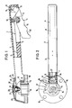
- a hand lever in its preferred embodiment according to the invention is denoted overall by 1.
- This hand lever 1 has an outer lever part 2, which, as shown, suitably consists of plastic and is designed as a closed housing. On the underside of the outer lever part 2, an opening 3 is provided which receives an actuating device, designated overall by 4. As can be seen in particular from FIG. 1 in connection with FIG. 2, the front end of the outer lever part 2 has two projections or teeth 5, which form the movable latching element of a latching device designated overall by 6. In the interior formed by the outer lever part 2, which is designed in the form of a housing, an inner lever part 7 is inserted, which advantageously consists of metal and has a U-profile cross section. Attached to this inner lever part 7 is the actuating device 4, which has an actuating pawl 8 which, in the locking position shown in FIG.
- This actuating pawl is pivotally mounted on the inner and preferably made of metal lever part 7 via a pivot bearing 9 and has a nose 10 at a distance from the pivot bearing 9, which on outer lever part 2 abuts.
- an inwardly pointing rib 11 can be provided, for example, in the interior of the outer lever part 2, so that the nose 10 engages directly in the space between this rib 11 and the rear end of the outer lever part 2 in order to provide a play-free and direct movement coupling of the actuating pawl 8 and to reach outer lever part 2.
- the actuating pawl 8 is constantly biased into its locking position shown in Fig.
- the compression spring 12 is supported on the inner surface of the inner lever part 7, which is stationary, and the other end of the compression spring 12 is received in a recess 13 of the actuating pawl 8.
- the preloading device, which is formed by the compression spring 12 is thus protected in the interior of the housing, which is formed by the outer lever part 2.
- the hand lever 1 is intended, for example, for actuating a butterfly valve in pipelines or the like, which is not shown in the drawing.
- a butterfly valve not shown, for example, an actuating shaft 14 is connected, which serves to rotate the flap with the aid of the hand lever 1.
- the front end of the stationary inner lever part 7 is fixedly connected, for example, by means of a screw 15 which passes through the inner lever part 7 and is screwed into the actuating shaft 14.
- a fixed element 16 of the latching device is arranged around the actuating shaft 14 and is likewise fixed by the connection of the screw 15 of the inner lever part 7 and the actuating shaft 14.
- the stationary element 16 of the latching device 6 has a ring gear 17 with teeth 18 projecting outwards.
- This ring gear 17 extends over an angular range of approximately 100 °, the outer teeth of the ring gear 17 having a larger tooth height than the others in order to reliably avoid exceeding the end positions.
- the teeth 18 on the ring gear 17 are expediently designed and arranged in such a way that locking in angular increments of approximately 16 ° is possible.
- the projections or teeth 5 provided on the outer lever part 2 engage in the locking position of the locking device 6 in the spaces between the teeth 18 of the ring gear 17 in order to lock the hand lever 1 in its desired position.
- the two teeth 5 on the outer lever part 2 engage one of the teeth 18 of the toothed rim 17, so that a secure locking is ensured.
- a protective cap 20 encloses the lever head part 19, so that the latching device 6 and the connection between the inner lever part 7 and the actuating shaft 14 are covered.
- an opening 21 is provided in the protective cap 20 in the region of the screw 15, into which an closure part 22 can be inserted, which is screwed into the screw 15, for example. If one releases this closure part 22 in the protective cap 22, the screw 15 is accessible from the outside with a tool which firmly connects the inner lever part to the actuating shaft 14. After loosening the closure part 22, the protective cap 20 can be removed, so that the latching device 6 is also accessible for maintenance and repair purposes.
- a display device 24 is shown, by means of which the locking position and the release position of the latching device 6 are displayed.
- This display device 24 has a slot-shaped opening 25 in the protective cap 20, into which a magnifying lens 26, for example, is inserted.
- the outer, movable lever part 2 carries markings 27, which are assigned to the locking position or the release position of the latching device 6. These markings 27 can be formed, for example, by adjacent color strips on the outer movable lever part 2, which can be clearly seen through the viewing window of the display device 24 formed by the slot-shaped opening 25 and the lens 26.
- the locking position of the latching device 6 is expediently assigned a red color stripe and the release position a green color stripe as the marking 27.
- the hand lever 1 is shown in its locking position, in which the teeth 5 on the outer lever part 2 engage in two successive recesses between the teeth 18 of the ring gear 17 of the latching device 6, so that the hand lever cannot be rotated.
- the color “red” can then be read on the display device 25.
- the actuating pawl 8 is slightly out of the opening 3 on the lower side of the outer lever part 2 and its ergonomically designed surface 30 is exposed downwards from the hand lever 1.
- the nose 10 of the actuating pawl 8 lies directly on the outer lever part 2.
- the flap not shown, is to be adjusted via the actuating shaft 14, an operator grips the outer lever part 2 of the hand lever 1 with one hand and the index and middle fingers of the hand come to rest on the ergonomically designed surface 30 of the actuating pawl 8. Now the actuating pawl 8 is pressed with the index and middle finger in the direction of the interior of the outer lever part 2 or in the direction of the inner lever part 7 against the action of the compression spring and the nose 10 of the actuating pawl 8 takes the outer lever part 2 by a small amount Distance with. Here, the outer lever part 2 is displaced along the inner lever part 7, as shown by an arrow in FIGS.
- the hand lever 1 is rotated while maintaining the pressed-in position of the actuating pawl 8 into the desired position, the green marking 27 being visible in the display device 24. If the desired new position of the hand lever 1 is now reached, the operator releases the actuating pawl 8 and this then reaches the position shown in FIG. 1 under the action of the compression spring 12. The nose 10 leads the outer lever part 2 back again, and the projections or teeth 5 on the outer lever part 2 snap back into the spaces between the teeth 18 of the ring gear 17 and the hand lever 1 is again locked in its new position. The red color marking 27 then appears again in the display device 24.
- the hand lever 1 can of course also be used to actuate devices other than a flap, as in the example shown.
- the hand lever 1 is compact, it has an ergonomically designed actuating pawl 8 and it is also designed to be visually appealing.
- the outer lever part 2, which is movable, can be made of thin-walled plastic, since the inner lever part 7 consists of metal and also serves as a stiffener for the hand lever 1 as a whole.
- the movable parts of the hand lever 1 are at least protected from dust, for which purpose in particular the protective cap 20 is provided on the lever head part 19 and the outer lever part 2 is designed and the inner lever part 7 and the actuating device 4, apart from the ergonomic trained surface 30 of the actuating pawl 8 largely completely.
Landscapes
- Engineering & Computer Science (AREA)
- General Engineering & Computer Science (AREA)
- Physics & Mathematics (AREA)
- General Physics & Mathematics (AREA)
- Automation & Control Theory (AREA)
- Mechanical Engineering (AREA)
- Mechanical Control Devices (AREA)
- Hand Tools For Fitting Together And Separating, Or Other Hand Tools (AREA)
- Mechanically-Actuated Valves (AREA)
Applications Claiming Priority (2)
| Application Number | Priority Date | Filing Date | Title |
|---|---|---|---|
| DE3710982 | 1987-04-01 | ||
| DE19873710982 DE3710982A1 (de) | 1987-04-01 | 1987-04-01 | Handhebel |
Publications (2)
| Publication Number | Publication Date |
|---|---|
| EP0284940A1 true EP0284940A1 (fr) | 1988-10-05 |
| EP0284940B1 EP0284940B1 (fr) | 1991-09-18 |
Family
ID=6324633
Family Applications (1)
| Application Number | Title | Priority Date | Filing Date |
|---|---|---|---|
| EP19880104471 Expired - Lifetime EP0284940B1 (fr) | 1987-04-01 | 1988-03-21 | Levier à main |
Country Status (5)
| Country | Link |
|---|---|
| US (1) | US4890506A (fr) |
| EP (1) | EP0284940B1 (fr) |
| JP (1) | JP2588575B2 (fr) |
| BR (1) | BR8801515A (fr) |
| DE (2) | DE3710982A1 (fr) |
Cited By (2)
| Publication number | Priority date | Publication date | Assignee | Title |
|---|---|---|---|---|
| EP0898104A3 (fr) * | 1997-08-19 | 1999-05-19 | Klinger AG | Robinet à tournant sphérique |
| EP1780455A1 (fr) * | 2005-10-28 | 2007-05-02 | Cepex, S.A.U. | Vanne à papillon |
Families Citing this family (14)
| Publication number | Priority date | Publication date | Assignee | Title |
|---|---|---|---|---|
| DE4133548C2 (de) * | 1991-10-10 | 1996-02-08 | Klein Schanzlin & Becker Ag | Handhebel |
| DE4432873C2 (de) * | 1994-09-15 | 1998-02-19 | Klein Schanzlin & Becker Ag | Handhebel und Verfahren zur Erzeugung einer Drehbewegung |
| ITMI981115A1 (it) * | 1998-05-20 | 1999-11-20 | Fip Formatura Inienzione Poli | Valvola a farfalla per un impianto idrico chimico e simili |
| USD412966S (en) | 1998-12-04 | 1999-08-17 | Newport News Shipbuilding And Drydock Company | Valve handle |
| US20040045613A1 (en) * | 2002-09-06 | 2004-03-11 | Waterway Plastics, Inc. | Diverter valve |
| US20040177716A1 (en) * | 2003-03-13 | 2004-09-16 | Heng-Chun Ku | Foot-adjusting handgrip |
| KR101290931B1 (ko) * | 2006-03-20 | 2013-07-29 | 아사히 유키자이 고교 가부시키가이샤 | 회전 밸브 |
| US20090045362A1 (en) * | 2007-04-20 | 2009-02-19 | Michna Ii Michael | Positive Locking Valve Control Device With Squeeze Trigger |
| US20090057584A1 (en) * | 2007-08-29 | 2009-03-05 | Strahman Valves, Inc. | Lockable Sampling Valve |
| USD601401S1 (en) * | 2008-12-19 | 2009-10-06 | Safety Tubs Holdings, Llc | Door handle for walk in bath tubs |
| US8061683B2 (en) * | 2009-03-30 | 2011-11-22 | Fisher Controls International, Llc | Manual valve operators having a lockout device |
| GB2566285B (en) * | 2017-09-07 | 2020-01-29 | Pegler Yorkshire Group Ltd | Valve handle locking mechanism |
| US11796080B2 (en) * | 2022-03-09 | 2023-10-24 | Nibco Inc. | Valve assembly |
| US12292126B2 (en) * | 2023-06-07 | 2025-05-06 | Scott Wu | Inflator valve connector |
Citations (5)
| Publication number | Priority date | Publication date | Assignee | Title |
|---|---|---|---|---|
| US1463333A (en) * | 1921-03-05 | 1923-07-31 | Deere & Co | Lever |
| US2206456A (en) * | 1937-03-05 | 1940-07-02 | Logan Gear Company | Manually operable control mechanism |
| GB786511A (en) * | 1955-01-27 | 1957-11-20 | Audley Engineering Co Ltd | Valve actuating means |
| GB859611A (en) * | 1958-07-30 | 1961-01-25 | Sackville Ltd | Improvements relating to hand brake levers for road vehicles |
| DE2043529A1 (de) * | 1969-09-30 | 1972-02-17 | Jamesbury Corp | Einstellgriff |
Family Cites Families (9)
| Publication number | Priority date | Publication date | Assignee | Title |
|---|---|---|---|---|
| US1313253A (en) * | 1919-08-19 | strandlttnd | ||
| GB190504460A (en) * | 1905-03-03 | 1905-10-05 | Henry Sleep | An Improvement connected with Taps or Cocks. |
| US3311128A (en) * | 1964-02-25 | 1967-03-28 | Daniel Orifice Fitting Company | Butterfly valve |
| GB1433831A (en) * | 1973-04-11 | 1976-04-28 | Bendix Westinghouse Ltd | Manual brake control valves |
| US4109673A (en) * | 1976-08-23 | 1978-08-29 | Sloan Valve Company | Combination gladhand and shutoff cock |
| US4193320A (en) * | 1978-05-08 | 1980-03-18 | Kubota Ltd. | Collapsible lever device for operating valve |
| GB2032579A (en) * | 1978-08-25 | 1980-05-08 | Saunders Valve Co Ltd | Fluid flow control valves |
| DE3125347C2 (de) * | 1981-06-27 | 1983-04-07 | Rheinische Armaturen- und Maschinenfabrik Albert Sempell, 4052 Korschenbroich | "Einstellbare Armaturenverriegelung" |
| DE3235320C2 (de) * | 1982-09-24 | 1984-07-12 | Klein, Schanzlin & Becker Ag, 6710 Frankenthal | Betätigungseinrichtung für eine Armatur |
-
1987
- 1987-04-01 DE DE19873710982 patent/DE3710982A1/de not_active Withdrawn
-
1988
- 1988-03-18 US US07/170,554 patent/US4890506A/en not_active Expired - Lifetime
- 1988-03-21 DE DE8888104471T patent/DE3864866D1/de not_active Expired - Lifetime
- 1988-03-21 EP EP19880104471 patent/EP0284940B1/fr not_active Expired - Lifetime
- 1988-03-30 BR BR8801515A patent/BR8801515A/pt not_active IP Right Cessation
- 1988-04-01 JP JP8211088A patent/JP2588575B2/ja not_active Expired - Lifetime
Patent Citations (5)
| Publication number | Priority date | Publication date | Assignee | Title |
|---|---|---|---|---|
| US1463333A (en) * | 1921-03-05 | 1923-07-31 | Deere & Co | Lever |
| US2206456A (en) * | 1937-03-05 | 1940-07-02 | Logan Gear Company | Manually operable control mechanism |
| GB786511A (en) * | 1955-01-27 | 1957-11-20 | Audley Engineering Co Ltd | Valve actuating means |
| GB859611A (en) * | 1958-07-30 | 1961-01-25 | Sackville Ltd | Improvements relating to hand brake levers for road vehicles |
| DE2043529A1 (de) * | 1969-09-30 | 1972-02-17 | Jamesbury Corp | Einstellgriff |
Cited By (2)
| Publication number | Priority date | Publication date | Assignee | Title |
|---|---|---|---|---|
| EP0898104A3 (fr) * | 1997-08-19 | 1999-05-19 | Klinger AG | Robinet à tournant sphérique |
| EP1780455A1 (fr) * | 2005-10-28 | 2007-05-02 | Cepex, S.A.U. | Vanne à papillon |
Also Published As
| Publication number | Publication date |
|---|---|
| JP2588575B2 (ja) | 1997-03-05 |
| US4890506A (en) | 1990-01-02 |
| EP0284940B1 (fr) | 1991-09-18 |
| DE3710982A1 (de) | 1988-10-20 |
| DE3864866D1 (de) | 1991-10-24 |
| JPS63255719A (ja) | 1988-10-24 |
| BR8801515A (pt) | 1988-11-08 |
Similar Documents
| Publication | Publication Date | Title |
|---|---|---|
| DE3447154C2 (de) | Drehsicherung für ein drehbar gelagertes Werkzeug, insbesondere ein Schneidwerkzeug eines Freischneidegerätes | |
| DE2362291C2 (de) | Sicherheitseinrichtung zum Verstellen einer zwischen einer Schließstellung und einer Öffnungsstellung gegen Federkraft verschwendbaren Sägeblattverkleidung | |
| DE3710982A1 (de) | Handhebel | |
| DE3709067A1 (de) | Medizinisches, insbesondere chirurgisches instrument | |
| DE2219658A1 (fr) | ||
| DE10317808A1 (de) | Handgriff für Ventile | |
| DE102009049317B4 (de) | Chirurgisches Instrument | |
| DE3307209C3 (de) | Fehlbedienungssicherungseinheit an einer Stulpschienen-Treibstangenbaueinheit eines Mehrfunktionenbeschlags, insbesondere eines Drehkippbeschlags | |
| DE2619031B1 (de) | Laengenveraenderlicher oberlenker | |
| DE3824729A1 (de) | Antriebsvorrichtung, insbesondere fuer schiebedaecher, schiebe-hebedaecher, fensterscheiben o.dgl. | |
| EP0782510B1 (fr) | Commutateur monte sur la colonne de direction, servant d'organe de changement de vitesses avec possibilite de fixation en position neutre | |
| DE3710981C2 (de) | Handhebel | |
| DE8707339U1 (de) | Handhebel | |
| DE3246396C2 (de) | Ausstellvorrichtung, insbesondere für Klappfenster von Kraftfahrzeugen, für Autohebedächer od. dgl. | |
| DE29922271U1 (de) | Chirurgisches Schiebeschaftinstrument | |
| DE3006405A1 (de) | Elektrisch betriebenes handgeraet | |
| DE102006054422B3 (de) | Messer | |
| DE102006026685B4 (de) | Sicherheitsvorrichtung für eine Zapfwelle | |
| DE9314581U1 (de) | Medizinisches Instrument | |
| DE8707341U1 (de) | Handhebel | |
| DE2949928C2 (de) | Gerät zum Entsteinen von Steinobst, wie Kirschen und Pflaumen | |
| DE3840218C2 (fr) | ||
| DE2903146A1 (de) | Arretierung fuer den schalter eines elektrowerkzeugs | |
| DE202008001745U1 (de) | Kappsäge mit Neigungsverstellung | |
| DE29603936U1 (de) | Mittelgriff für den Führungsstiel von Gartengeräten |
Legal Events
| Date | Code | Title | Description |
|---|---|---|---|
| PUAI | Public reference made under article 153(3) epc to a published international application that has entered the european phase |
Free format text: ORIGINAL CODE: 0009012 |
|
| AK | Designated contracting states |
Kind code of ref document: A1 Designated state(s): CH DE FR GB IT LI |
|
| 17P | Request for examination filed |
Effective date: 19881223 |
|
| 17Q | First examination report despatched |
Effective date: 19901128 |
|
| GRAA | (expected) grant |
Free format text: ORIGINAL CODE: 0009210 |
|
| AK | Designated contracting states |
Kind code of ref document: B1 Designated state(s): CH DE FR GB IT LI |
|
| REF | Corresponds to: |
Ref document number: 3864866 Country of ref document: DE Date of ref document: 19911024 |
|
| ET | Fr: translation filed | ||
| ITF | It: translation for a ep patent filed | ||
| GBT | Gb: translation of ep patent filed (gb section 77(6)(a)/1977) | ||
| PLBE | No opposition filed within time limit |
Free format text: ORIGINAL CODE: 0009261 |
|
| STAA | Information on the status of an ep patent application or granted ep patent |
Free format text: STATUS: NO OPPOSITION FILED WITHIN TIME LIMIT |
|
| 26N | No opposition filed | ||
| PGFP | Annual fee paid to national office [announced via postgrant information from national office to epo] |
Ref country code: GB Payment date: 19970227 Year of fee payment: 10 |
|
| PGFP | Annual fee paid to national office [announced via postgrant information from national office to epo] |
Ref country code: FR Payment date: 19970319 Year of fee payment: 10 |
|
| PGFP | Annual fee paid to national office [announced via postgrant information from national office to epo] |
Ref country code: CH Payment date: 19970324 Year of fee payment: 10 |
|
| PGFP | Annual fee paid to national office [announced via postgrant information from national office to epo] |
Ref country code: DE Payment date: 19970328 Year of fee payment: 10 |
|
| PG25 | Lapsed in a contracting state [announced via postgrant information from national office to epo] |
Ref country code: GB Free format text: LAPSE BECAUSE OF NON-PAYMENT OF DUE FEES Effective date: 19980321 |
|
| PG25 | Lapsed in a contracting state [announced via postgrant information from national office to epo] |
Ref country code: LI Free format text: LAPSE BECAUSE OF NON-PAYMENT OF DUE FEES Effective date: 19980331 Ref country code: FR Free format text: THE PATENT HAS BEEN ANNULLED BY A DECISION OF A NATIONAL AUTHORITY Effective date: 19980331 Ref country code: CH Free format text: LAPSE BECAUSE OF NON-PAYMENT OF DUE FEES Effective date: 19980331 |
|
| GBPC | Gb: european patent ceased through non-payment of renewal fee |
Effective date: 19980321 |
|
| REG | Reference to a national code |
Ref country code: CH Ref legal event code: PL |
|
| PG25 | Lapsed in a contracting state [announced via postgrant information from national office to epo] |
Ref country code: DE Free format text: LAPSE BECAUSE OF NON-PAYMENT OF DUE FEES Effective date: 19981201 |
|
| REG | Reference to a national code |
Ref country code: FR Ref legal event code: ST |
|
| PG25 | Lapsed in a contracting state [announced via postgrant information from national office to epo] |
Ref country code: IT Free format text: LAPSE BECAUSE OF NON-PAYMENT OF DUE FEES;WARNING: LAPSES OF ITALIAN PATENTS WITH EFFECTIVE DATE BEFORE 2007 MAY HAVE OCCURRED AT ANY TIME BEFORE 2007. THE CORRECT EFFECTIVE DATE MAY BE DIFFERENT FROM THE ONE RECORDED. Effective date: 20050321 |