EP0285154A2 - System zum Anschluss mehrerer Endgeräte an eine Netzabschlusseinrichtung in einem Breitbandnachrichtennetz - Google Patents
System zum Anschluss mehrerer Endgeräte an eine Netzabschlusseinrichtung in einem Breitbandnachrichtennetz Download PDFInfo
- Publication number
- EP0285154A2 EP0285154A2 EP19880105236 EP88105236A EP0285154A2 EP 0285154 A2 EP0285154 A2 EP 0285154A2 EP 19880105236 EP19880105236 EP 19880105236 EP 88105236 A EP88105236 A EP 88105236A EP 0285154 A2 EP0285154 A2 EP 0285154A2
- Authority
- EP
- European Patent Office
- Prior art keywords
- bus
- terminal
- terminals
- transmission
- network termination
- Prior art date
- Legal status (The legal status is an assumption and is not a legal conclusion. Google has not performed a legal analysis and makes no representation as to the accuracy of the status listed.)
- Granted
Links
Images

Classifications
-
- H—ELECTRICITY
- H04—ELECTRIC COMMUNICATION TECHNIQUE
- H04L—TRANSMISSION OF DIGITAL INFORMATION, e.g. TELEGRAPHIC COMMUNICATION
- H04L12/00—Data switching networks
- H04L12/28—Data switching networks characterised by path configuration, e.g. LAN [Local Area Networks] or WAN [Wide Area Networks]
- H04L12/40—Bus networks
- H04L12/403—Bus networks with centralised control, e.g. polling
- H04L12/4035—Bus networks with centralised control, e.g. polling in which slots of a TDMA packet structure are assigned based on a contention resolution carried out at a master unit
-
- H—ELECTRICITY
- H04—ELECTRIC COMMUNICATION TECHNIQUE
- H04L—TRANSMISSION OF DIGITAL INFORMATION, e.g. TELEGRAPHIC COMMUNICATION
- H04L12/00—Data switching networks
- H04L12/28—Data switching networks characterised by path configuration, e.g. LAN [Local Area Networks] or WAN [Wide Area Networks]
- H04L12/40—Bus networks
-
- H—ELECTRICITY
- H04—ELECTRIC COMMUNICATION TECHNIQUE
- H04L—TRANSMISSION OF DIGITAL INFORMATION, e.g. TELEGRAPHIC COMMUNICATION
- H04L12/00—Data switching networks
- H04L12/28—Data switching networks characterised by path configuration, e.g. LAN [Local Area Networks] or WAN [Wide Area Networks]
- H04L12/42—Loop networks
-
- H—ELECTRICITY
- H04—ELECTRIC COMMUNICATION TECHNIQUE
- H04Q—SELECTING
- H04Q11/00—Selecting arrangements for multiplex systems
- H04Q11/04—Selecting arrangements for multiplex systems for time-division multiplexing
-
- H—ELECTRICITY
- H04—ELECTRIC COMMUNICATION TECHNIQUE
- H04Q—SELECTING
- H04Q11/00—Selecting arrangements for multiplex systems
- H04Q11/04—Selecting arrangements for multiplex systems for time-division multiplexing
- H04Q11/0428—Integrated services digital network, i.e. systems for transmission of different types of digitised signals, e.g. speech, data, telecentral, television signals
-
- H—ELECTRICITY
- H04—ELECTRIC COMMUNICATION TECHNIQUE
- H04Q—SELECTING
- H04Q11/00—Selecting arrangements for multiplex systems
- H04Q11/04—Selecting arrangements for multiplex systems for time-division multiplexing
- H04Q11/0428—Integrated services digital network, i.e. systems for transmission of different types of digitised signals, e.g. speech, data, telecentral, television signals
- H04Q11/0435—Details
- H04Q11/0471—Terminal access circuits
-
- H—ELECTRICITY
- H04—ELECTRIC COMMUNICATION TECHNIQUE
- H04Q—SELECTING
- H04Q11/00—Selecting arrangements for multiplex systems
- H04Q11/04—Selecting arrangements for multiplex systems for time-division multiplexing
- H04Q11/0428—Integrated services digital network, i.e. systems for transmission of different types of digitised signals, e.g. speech, data, telecentral, television signals
- H04Q11/0478—Provisions for broadband connections
-
- H—ELECTRICITY
- H04—ELECTRIC COMMUNICATION TECHNIQUE
- H04J—MULTIPLEX COMMUNICATION
- H04J2203/00—Aspects of optical multiplex systems other than those covered by H04J14/05 and H04J14/07
- H04J2203/0001—Provisions for broadband connections in integrated services digital network using frames of the Optical Transport Network [OTN] or using synchronous transfer mode [STM], e.g. SONET, SDH
- H04J2203/0046—User Network Interface
- H04J2203/0048—Network termination, e.g. NT1, NT2, PBX
-
- H—ELECTRICITY
- H04—ELECTRIC COMMUNICATION TECHNIQUE
- H04J—MULTIPLEX COMMUNICATION
- H04J2203/00—Aspects of optical multiplex systems other than those covered by H04J14/05 and H04J14/07
- H04J2203/0001—Provisions for broadband connections in integrated services digital network using frames of the Optical Transport Network [OTN] or using synchronous transfer mode [STM], e.g. SONET, SDH
- H04J2203/0046—User Network Interface
- H04J2203/005—Terminal equipment, e.g. codecs, synch
-
- H—ELECTRICITY
- H04—ELECTRIC COMMUNICATION TECHNIQUE
- H04Q—SELECTING
- H04Q2213/00—Indexing scheme relating to selecting arrangements in general and for multiplex systems
- H04Q2213/003—Constructional details
-
- H—ELECTRICITY
- H04—ELECTRIC COMMUNICATION TECHNIQUE
- H04Q—SELECTING
- H04Q2213/00—Indexing scheme relating to selecting arrangements in general and for multiplex systems
- H04Q2213/29—ATM
-
- H—ELECTRICITY
- H04—ELECTRIC COMMUNICATION TECHNIQUE
- H04Q—SELECTING
- H04Q2213/00—Indexing scheme relating to selecting arrangements in general and for multiplex systems
- H04Q2213/292—Time (de)multiplexing
-
- H—ELECTRICITY
- H04—ELECTRIC COMMUNICATION TECHNIQUE
- H04Q—SELECTING
- H04Q2213/00—Indexing scheme relating to selecting arrangements in general and for multiplex systems
- H04Q2213/298—Loop or ring system
-
- H—ELECTRICITY
- H04—ELECTRIC COMMUNICATION TECHNIQUE
- H04Q—SELECTING
- H04Q2213/00—Indexing scheme relating to selecting arrangements in general and for multiplex systems
- H04Q2213/299—Bus
-
- H—ELECTRICITY
- H04—ELECTRIC COMMUNICATION TECHNIQUE
- H04Q—SELECTING
- H04Q2213/00—Indexing scheme relating to selecting arrangements in general and for multiplex systems
- H04Q2213/332—Broadband system
Definitions
- the invention relates to a system for the simultaneous operation of a plurality of terminals on a subscriber-side network termination device in a digital broadband message network, the signals transmitted and received by the terminals and transmitted in the network being transmitted according to the principle of time division technology with asynchronous time allocation.
- the entry "A Multi-Bit-Rate Asynchronous Time-Devision Equipment at the Subscriber Premises" describes a possibility of connecting several terminal devices with different bit rates to a network termination device.
- the signals of the individual channels are structured in packets, each packet containing 128 bits, of which 120 bits are used for the transmission of the useful information, and 8 bits are used as the packet header to identify the channel.
- the terminals TE 1 to TE N of different bit rate are connected via three bus lines to the network termination device NT, which terminates the four-wire subscriber line As1 of the telecommunications network and consists of an adapter AE and the distributor Z.
- the three bus lines are the receive bus EB, the send bus SB and the so-called assignment bus ZB.
- the signals arriving on the Asl are transmitted on the bus EB to the terminals TE at the same bit rate as on this.
- each terminal TE processes only the packets assigned to it.
- the time allocation of the packets to the different terminals TE is asynchronous; the next package immediately follows the previous one. From time to time, so-called empty packets of 128 bits in length, which contain a special bit pattern that is used to synchronize the time multiple in each terminal TE, are interspersed in the time-division multiplex signal.
- all terminal devices TE transmit their signals in a packetized form to the transmission bus SB. Since a procedure similar to that used for ISDN is not provided here, the signals of the individual terminals TE could collide, making the information unrecognizable. To prevent this, there is the allocation bus ZB, which is controlled by the allocation z. A time grid is transmitted to the allocation bus ZB, one grid step corresponding to the packet length. The individual time slots are assigned to the various terminal devices TE according to their capacity requirements. Within these time slots, the terminals TE deliver their packets to the send bus SB at a significantly higher bit rate than is used on the Asl.
- an isochronous bit stream is formed for the connecting line Asl from the signals received by the transmission bus SB, in which one packet follows the next without space.
- each terminal must be connected to three bus lines to be installed.
- the data speed on the transmission bus SB must be higher than on the connection line Asl.
- the length of the connecting cables of the terminal devices TE is subject to certain restrictions in such a way that the electrically relevant total distance of each terminal device TE from the network termination device NT is an integral multiple is the line length, the duration of which corresponds to the duration of a bit. This is the only way to ensure that an isochronous data signal is generated on the transmission bus, for which simple regeneration, including clock recovery, is required.
- a solution proposed by the user for the same task for an ISDN B network does not include the disadvantages described above, but is limited to synchronous transmission.
- the invention is therefore based on the object of specifying a method which does not have the disadvantages listed above and in which in particular only one transmission bus SB and one reception bus EB exist.
- the data speed on the transmission bus SB should be identical to that on the connection line Asl. There are therefore no variable protection times between the packets sent by the individual end devices.
- This object is achieved in a system for the simultaneous operation of several terminals on a subscriber-side network termination device in a digital broadband message network with time multiple transmission and asynchronous time slot assignment, in which the transmission between the network termination device and the terminals takes place via a passive reception bus, in that for the transmission between terminals and Network termination device an active, ring-shaped transmission bus is provided.
- Each terminal also points like the network termination device each have a transmitter and a receiver for the transmission bus. The transmitter and receiver for the transmission bus are connected to one another in the terminals via a data insertion device which inserts the data from each terminal into the bit stream transmitted on the transmission bus.
- the functional groups receiver E S , data insertion device DE and transmitter S S in shown in FIG. 2 for the terminal TE 1 above a broken line the device junction box.
- the advantages that can be achieved with the invention are, in particular, that between the data packets sent out by the various terminal devices, no more protection times are required to avoid signal collisions, and thus no conversion of the speed of the time multiples occurring on the transmission bus SB is required for the transmission on the connecting line Asl is.
- the number of bus lines required in the subscriber station becomes reduced from three to two. Because the signals on the transmission bus SB are regenerated in practically every terminal, the transmission bus can have a larger extension.
- each terminal TE has a receiver E E , which uses the address in the packet header to select only the packets intended for the relevant terminal TE from the received data stream for further processing in the terminal.
- the network termination device NT also contains a transmitter S S which , in the event that no terminal TE is active, emits a continuous sequence of so-called empty packets L.
- Each empty packet L transmits with part of its capacity of e.g. B. 64 bit a synchronous pattern SY, which makes it possible to immediately synchronize to the packet boundaries without using the flywheel principle or the like.
- the 64-bit combination is, for example, expressed in hexadecimal "65 AE F3 15 3F 41 C2 46" (described in "Specification of Transmission System for the Broadcasting-Satellite Service", CCIR Special Publication, Geneva, April 1986).
- the sequence of idle packets is received in each terminal TE of the receiver E S and, via the data inserting means to the transmitter DE S S, which it sends out for the next section of the ring line SB. After going through all the terminals TE will eventually receive the signal from the receiver E S in the network termination NT.
- a code is used for the transmission on the transmission bus SB, the power density spectrum of which has no DC component, e.g. B. a CMI code. This makes it possible to supply the terminals TE remotely from the network termination device NT by means of simple LC combinations via the transmission bus SB.
- the request for a connection so in the data insertion device DE from the terminal TE 1 the next possible empty packet by a packet "REQU 1" with a corresponding request to Network termination device NT replaced.
- the REQU 1 request package is completed by the functional groups E S , DE and S S of the subsequent terminals TE 2 and TE 3 are looped and thereby delayed by the running time ⁇ .
- the network termination device recognizes the connection request and at the time t2 by a packet "START 1" the request to send to the terminal TE 1.
- TE 1 begins at time t3 with the transmission of data packets "DATA 1", which in turn by the function groups E S , DE and S S can be ground.
- the START packets are also looped back to the network termination device NT.
- the start procedure for the terminal TE 2 takes place from t4 to t6.
- TE 1 signals the end of its transmission by means of a “STOP 1” packet.
- the temporal signal curve shown in FIG. 3 could give the impression that the terminals TE located at the end of the transmission bus SB are disadvantaged in terms of access to the latter. This is only correct with regard to a larger average delay when sending data packets.
- the general availability is guaranteed.
- the control in the network termination device NT has to be designed in such a way that only so many terminals TE are given permission to transmit that the sum of the data rates of all terminals TE in operation is somewhat smaller than the data rate on the ring line of the transmission bus SB. If this requirement is met, there are still enough empty packets available to synchronize the time multiple, even when the SB bus is fully loaded.
- the terminal TE 3 shown in somewhat more detail in the lower part of FIG. 2 illustrates the function of essential parts of a terminal TE.
- the data insertion device DE Provided that the terminal TE is in the operating state and an empty packet is detected by the data insertion device DE, the data insertion device DE outputs a control signal St to the device-internal packetizer, whereby from this with the obtained in E S ring line clock T is a data packet on the line SD to the data insertion apparatus DE is given. This puts the data packet in the place of the previously identified empty packet.
- the lines EB and SB can be designed as coaxial or as optical waveguide lines. In the latter case, additional electro-optical converters and a separate supply of the power supply are then required.
Landscapes
- Engineering & Computer Science (AREA)
- Computer Networks & Wireless Communication (AREA)
- Signal Processing (AREA)
- Small-Scale Networks (AREA)
Abstract
Description
- Die Erfindung betrifft ein System zum gleichzeitigen Betrieb mehrerer Endgeräte an einer teilnehmerseitigen Netzabschlußeinrichtung in einem digitalen Breitbandnachrichtennetz, wobei die von den Endgeräten gesendeten und empfangenen sowie im Netz übermittelten Signale nach dem Prinzip der Zeitvielfachtechnik mit asynchroner Zeitlagenzuordnung übertragen werden.
- Im Konferenzband des ISSLS 1984 in Nizza ist in dem Beitrag "A Multi-Bit-Rate Asynchronous Time-Devision Equipment at the Subscriber Premises" eine Möglichkeit des Anschlusses von mehreren Endgeräten unterschiedlichster Bitrate an eine Netzabschlußeinrichtung beschrieben. Die Signale der einzelnen Kanäle sind in Pakete strukturiert, wobei jedes Paket 128 bit enthält, von denen 120 bit der Übertragung der Nutzinformation, und 8 bit als Paketkopf zur Kennzeichnung des Kanals dienen. Wie in Fig. 1 dargestellt, sind die Endgeräte TE 1 bis TE N unterschiedlichster Bitrate über drei Busleitungen mit der Netzabschlußeinrichtung NT verbunden, die die vierdrähtige Teilnehmeranschlußleitung As1 des Fernmeldenetzes abschließt und aus einer Anpaßeinrichtung AE und dem Zuteiler Z besteht. Bei den drei Busleitungen handelt es sich um den Empfangsbus EB, den Sendebus SB und den sog. Zuteilungsbus ZB. Auf dem Bus EB werden die auf der Asl ankommenden Signale zu den Endgeräten TE mit der gleichen Bitrate wie auf dieser übertragen. Entsprechend der Paketadresse verarbeitet jedes Endgerät TE nur die ihm zugeordneten Pakete. Die zeitliche Zuordnung der Pakete zu den verschiedenen Endgeräten TE ist asynchron; das nächstfolgende Paket schließt unmittelbar an das vorhergehende an. Von Zeit zu Zeit sind sog. Leerpakete von 128 bit Länge, die ein spezielles Bitmuster enthalten, das zur Synchronisation des Zeitvielfachs in jedem Endgerät TE verwendet wird, in das Zeitmultiplexsignal eingestreut.
- In Senderichtung geben alle Endgeräte TE ihre Signale in paketierter Form an den Sendebus SB ab. Da eine ähnliche Prozedur, wie sie beim ISDN verwendet wird, hier nicht vorgesehen ist, könnte es zu Kollisionen der Signale der einzelnen Endgeräte TE kommen, wodurch die Information unkenntlich würde. Um dies zu verhindern, gibt es den Zuteilungsbus ZB, der vom Zuteiler Z gesteuert wird. Auf den Zuteilungsbus ZB wird ein Zeitraster übertragen, wobei eine Rasterstufe der Paketlänge entspricht. Die einzelnen Zeitlagen werden den verschiedenen Endgeräten TE entspechend deren Kapazitätsbedarf zugeordnet. Innerhalb dieser Zeitlagen geben die Endgeräte TE ihre Pakete an den Sendebus SB mit einer nennenswert höheren Bitrate ab, als sie abgehend auf der Asl verwendet wird. Dies ist erfor derlich, damit zwischen den von den in Betrieb befindlichen Endgeräten TE gesendeten Paketen eine mehr oder wenige große Schutzzeit entsteht, die verhindert, daß es zu zeitlichen Überschneidungen der Pakete kommt. Diese Überschneidungen würden durch die unterschiedliche elektrische Entfernung der Endgeräte TE von der Netzabschlußeinrichtung NT und die damit verbundenen unterschiedlichen Laufzeiten der Signale sowohl auf den Zuteilungsbus ZB, als auch auf den Sendebus SB hervorgerufen.
- In der zu der Netzabschlußeinrichtung NT gehörenden Anpaßeinrichtung wird für die Anschlußleitung Asl abgehend ein isochroner Bitstrom aus den vom Sendebus SB empfangenen Signalen gebildet, in dem ein Paket dem nächsten ohne Zwischenraum folgt.
- Das geschilderte Verfahren hat den entscheidenden Nachteil, daß jedes Endgerät mit drei zu installierenden Busleitungen verbunden werden muß. Hinzu kommt, daß wegen der erwähnten erforderlichen Schutzzeiten die Datengeschwindigkeit auf dem Sendebus SB höher sein muß als auf der Anschlußleitung Asl. Damit verbunden ist eine notwendige Umsetzung der Datengeschwindigkeit in abgehender Richtung in der Netzabschlußeinrichtung NT. Außerdem unterliegt die Länge der Anschlußkabel der Endgeräte TE gewissen Einschränkungen in der Weise, daß die elektrisch maßgebliche Gesamtentfernung jedes Endgerätes TE von der Netzabschlußeinrichtung NT ein ganzzahliges Vielfaches der Leitungslänge ist, deren Laufzeit der Dauer eines Bits entspricht. Nur so kann sichergestellt werden, daß auf dem Sendebus ein isochrones Datensignal entsteht, für das eine einfache Regeneration einschließlich Taktrückgewinnung benötigt wird. Eine von eigener Seite vorgeschlagene Lösung der gleichen Aufgabe für ein ISDN-B-Netz beinhaltet die oben dargestellten Nachteile zwar nicht, ist aber auf synchrone Übertragung beschränkt.
- Der Erfindung liegt deshalb die Aufgabe zugrunde ein Verfahren anzugeben, das die vorstehend aufgeführten Nachteile nicht hat und bei dem insbesonders nur ein Sendebus SB und ein Empfangsbus EB existieren. Die Datengeschwindigkeit auf dem Sendebus SB soll dabei identisch derjenigen auf der Anschlußleitung Asl sein. Es existieren also keine variablen Schutzzeiten zwischen den von den einzelnen Endgeräten ausgesendeten Paketen.
- Diese Aufgabe wird bei einem System zum gleichzeitigen Betrieb mehrerer Endgeräte an einer teilnehmerseitigen Netzabschlußeinrichtung in einem digitalen Breitbandnachrichtennetz mit Zeitvielfachübertragung und asynchroner Zeitlagenzuordnung, bei dem die Übertragung zwischen Netzabschlußeinrichtung und den Endgeräten über einen passiven Empfangsbus erfolgt, dadurch gelöst, daß für die Übertragung zwischen Endgeräten und Netzabschlußeinrichtung ein aktiver, ringförmig ausgebildeter Sendebus vorgesehen ist. Jedes Endgerät weist ebenso wie die Netzabschlußeinrichtung je einen Sender und je einen Empfänger für den Sendebus auf. Sender und Empfänger für den Sendebus sind in den Endgeräten über eine Dateneinfügungseinrichtung miteinander verbunden, welche die Daten jedes Endgerätes in den auf dem Sendebus übertragenen Bitstrom einfügt.
- Um zu verhindern, daß infolge eines Defekts in der üblicherweise flexiblen Anschlußschnur eines Endgerätes TE der Sendebus SB unterbrochen wird, sind vorteilhaft die in Fig. 2 beim Endgerät TE 1 oberhalb einer gestrichelten Linie dargestellten Funktionsgruppen Empfänger ES, Dateneinfügungseinrichtung DE und Sender SS in der Geräteanschlußdose untergebracht.
- Die mit der Erfindung erzielbaren Vorteile bestehen insbesondere darin, daß zwischen den von den verschiedenen Endgeräten ausgesendeten Datenpaketen keine Schutzzeiten zur Vermeidung von Signalkollissionen mehr erforderlich sind und somit keine Umsetzung der Geschwindigkeit des auf dem Sendebus SB entstehenden Zeitvielfachs für die Übertragung auf der Anschlußleitung Asl mehr eforderlich ist. Außerdem wird durch Wegfallen des beim Stand der Technik beschriebenen Zuteilungsbus ZB die Anzahl der in der Teilnehmerstation erforderlichen Buslei tungen von drei auf zwei verringert. Dadurch, daß die Signale auf dem Sendebus SB praktisch in jedem Endgerät regeneriert werden, kann der Sendebus eine größere Ausdehnung haben.
- Ein Ausführungsbeispiel nach der Erfindung wird anhand der Figuren 1 bis 3 näher erläutert.
- Es zeigen:
- Fig. 1 eine Anschlußkonfiguration nach dem bereits geschilderten Stand der Technik
- Fig. 2 das Funktionsschaltbild eines Beispiels mit drei Endgeräten TE 1 bis TE 3 für eine Anschlußkonfiguration nach der Erfindung
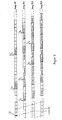
- Fig. 3 den zugehörigen zeitlichen Signalverlauf an den Ausgängen der Netzabschlußeinrichtung NT und der Endgeräte TE 1 bis TE 3 bezüglich der Ringleitung SB.
- In Fig. 2 ist in der Netzabschlußeinrichtung NT ein Sender SE dargestellt, der die von der Anschlußleitung Asl empfangenen Signale in bekannter Weise in den passiven, am Ende mit dem Wellenwiderstand Z abgeschlossenen Empfangsbus EB einspeist. Jedes Endgerät TE besitzt einen Empfänger EE, der anhand der Adresse im Paketkopf nur die für das betreffende Endgerät TE bestimmten Pakete aus dem empfangenen Datenstrom zur weiteren Verarbeitung im Endgerät auswählt.
- Die Netzabschlußeinrichtung NT enthält weiterhin einen Sender SS, der für den Fall, daß noch kein Endgerät TE aktiv ist, eine kontinuierliche Folge von sog. Leerpaketen L aussendet. Jedes Leerpaket L überträgt mit einem Teil seiner Kapazität von z. B. 64 bit ein Synchronmuster SY, wodurch es möglich ist, sofort ohne Anwendung des Schwungradprinzips o. ä., auf die Paketgrenzen zu synchronisieren. Die 64-bit-Kombination lautet beispielsweise, hexadezimal ausgedrückt "65 AE F3 15 3F 41 C2 46" (Beschrieben in "Specification of Transmission System for the Broadcasting-Satellite Service", CCIR Special Publication, Genf, April 1986). Die Folge der Leerpakete wird in jedem Endgerät TE von dessen Empfänger ES empfangen und über die Dateneinfügungseinrichtung DE an den Sender SS gegeben, der sie für den nächsten Abschnitt der Ringleitung SB aussendet. Nach Durchlaufen sämtlicher Endgeräte TE wird das Signal schließlich vom Empfänger ES in der Netzabschlußeinrichtung NT empfangen. Für die Übertragung auf dem Sendebus SB wird ein Code verwendet, dessen Leistungsdichtespektrum keinen Gleichstromanteil hat, z. B. ein CMI-Code. Dadurch ist die Fernspeisung der Endgeräte TE von der Netzabschlußeinrichtung NT aus mittels einfacher L-C-Kombinationen über den Sendebus SB möglich. Besteht nun, wie in Fig. 3 dargestellt, beim Endgerät TE 1 zum Zeitpunkt t₁ die Anforderung nach einem Verbindungsaufbau, so wird in der Dateneinfügungseinrichtung DE von dem Endgerät TE 1 das nächstmögliche Leerpaket durch ein Paket "REQU 1" mit einer entsprechenden Anfrage an die Netzbabschlußeinrichtung NT ersetzt. Das Anforderungspaket REQU 1 wird durch die Funktionsgruppen ES, DE und SS der nachfolgenden Endgeräte TE 2 und TE 3 geschleift und dabei jeweils um die Laufzeit τ verzögert. Die Netzabschlußeinrichtung erkennt den Verbindungswunsch und gibt zur Zeit t₂ durch ein Paket "START 1" die Aufforderung zum Senden an das Endgerät TE 1. TE 1 beginnt zum Zeitpunkt t₃ mit dem Aussenden von Datenpaketen "DATEN 1", die wiederum durch die Funktionsgruppen ES, DE und SS geschleift werden. Um die Dateneinfügungseinrichtung DE in den Endgeräten nicht zu aufwendig zu gestalten, werden auch die START-Pakete bis zurück zu der Netzabschlußeinrichtung NT durchgeschleift. In gleicher Weise wie vorstehend beschrieben findet von t₄ bis t₆ die Startprozedur für das Endgeräte TE 2 statt. Zum Zeitpunkt t₇ signalisiert TE 1 durch ein Paket "STOP 1" das Ende seiner Aussendung.
- Durch den in Fig. 3 dargestellten zeitlichen Signalverlauf könnte der Eindruck entstehen, als ob die am Ende der Ringleitung Sendebus SB befindlichen Endgeräte TE bezüglich des Zugriffs zu dieser benachteiligt seien. Dies ist nur bezüglich einer größeren durchschnittlichen Verzögerung beim Absetzen von Datenpaketen richtig. Die generelle Verfügbarkeit ist gewährleistet. Die Steuerung in der Netzabschlußeinrichtung NT muß nämlich so ausgelegt sein, daß nur so vielen Endgeräten TE die Sendeerlaubnis gegeben wird, daß die Summe der Datenraten aller in Betrieb befindlichen Endgeräten TE etwas kleiner ist als die Datenrate auf der Ringleitung des Sendebus SB. Sofern diese Forderung erfüllt ist, stehen auch bei voller Auslastung vom Sendebus SB am letzten Endgerät noch genügend Leerpakete zur Synchronisierung des Zeitvielfachs zur Verfügung.
- Das im unteren Teil der Fig. 2 etwas detailierter dargestellte Endgerät TE 3 verdeutlicht die Funktion wesentlicher Teile eines Endgerätes TE. Sofern sich das Endgerät TE im Betriebszustand befindet und von der Dateneinfügungseinrichtung DE ein Leerpaket erkannt wird, gibt die Dateneinfügungseinrichtung DE ein Steuersignal St an den geräteinternen Paketierer, wodurch aus diesem mit dem in ES gewonnenen Ringleitungstakt T ein Datenpaket auf der Leitung SD an die Dateneinfügungeinrichtung DE gegeben wird. Diese setzt das Datenpaket an die Stelle des zuvor identifizierten Leerpakets.
- Die Leitungen EB und SB können als Koaxial- oder als Lichtwellenleiterleitungen ausgelegt sein. Im letzteren Fall sind dannn zusätzlich elektro-optische Wandler und eine gesonderte Zuführung der Stromversorgung erforderlich.
Claims (3)
wobei jedes Endgerät (TE1, TE2 ...) ebenso wie die Netzabschlußeinrichtung (NT) je einen Sender (SS) und je einen Empfänger(ES) für den Sendebus (SB) aufweist, die in den Endgeräten über eine Dateneinfügungseinrichtung (DE) miteinander verbunden sind, welche die Daten jedes Endgerätes in den auf dem Sendebus (SB) übertragenen Bitstrom einfügt (Fig. 2).
Applications Claiming Priority (2)
| Application Number | Priority Date | Filing Date | Title |
|---|---|---|---|
| DE3710868 | 1987-04-01 | ||
| DE3710868 | 1987-04-01 |
Publications (3)
| Publication Number | Publication Date |
|---|---|
| EP0285154A2 true EP0285154A2 (de) | 1988-10-05 |
| EP0285154A3 EP0285154A3 (de) | 1991-09-25 |
| EP0285154B1 EP0285154B1 (de) | 1994-06-15 |
Family
ID=6324571
Family Applications (1)
| Application Number | Title | Priority Date | Filing Date |
|---|---|---|---|
| EP88105236A Expired - Lifetime EP0285154B1 (de) | 1987-04-01 | 1988-03-31 | System zum Anschluss mehrerer Endgeräte an eine Netzabschlusseinrichtung in einem Breitbandnachrichtennetz |
Country Status (3)
| Country | Link |
|---|---|
| EP (1) | EP0285154B1 (de) |
| JP (1) | JP2641487B2 (de) |
| DE (1) | DE3850161D1 (de) |
Cited By (3)
| Publication number | Priority date | Publication date | Assignee | Title |
|---|---|---|---|---|
| FR2647612A1 (fr) * | 1989-05-24 | 1990-11-30 | American Telephone & Telegraph | Dispositif, procede et reseau de transmission de donnees multipoint et multicanal |
| WO1999043129A1 (de) * | 1998-02-23 | 1999-08-26 | Siemens Aktiengesellschaft | Modulares automatisierungssystem, verfahren zum betrieb eines modularen automatisierungssystems und bussystem für automatisierungsgeräte |
| EP0663786A3 (de) * | 1993-12-14 | 1999-12-22 | KE KOMMUNIKATIONS-ELEKTRONIK GMBH & CO | Verfahren zur digitalen Datenübertragung |
Family Cites Families (4)
| Publication number | Priority date | Publication date | Assignee | Title |
|---|---|---|---|---|
| JPS5336110A (en) * | 1976-09-16 | 1978-04-04 | Fujitsu Ltd | Data transfer system |
| ATE25906T1 (de) * | 1982-12-28 | 1987-03-15 | Ibm | Vielfachverbindungssystem fuer teilnehmerstationen. |
| US4627050A (en) * | 1984-05-22 | 1986-12-02 | Rolm Corporation | Time division multiplexed computerized branch exchange |
| US4641276A (en) * | 1984-10-22 | 1987-02-03 | General Electric Company | Serial-parallel data transfer system for VLSI data paths |
-
1988
- 1988-03-31 DE DE3850161T patent/DE3850161D1/de not_active Expired - Fee Related
- 1988-03-31 EP EP88105236A patent/EP0285154B1/de not_active Expired - Lifetime
- 1988-04-01 JP JP63078291A patent/JP2641487B2/ja not_active Expired - Lifetime
Cited By (3)
| Publication number | Priority date | Publication date | Assignee | Title |
|---|---|---|---|---|
| FR2647612A1 (fr) * | 1989-05-24 | 1990-11-30 | American Telephone & Telegraph | Dispositif, procede et reseau de transmission de donnees multipoint et multicanal |
| EP0663786A3 (de) * | 1993-12-14 | 1999-12-22 | KE KOMMUNIKATIONS-ELEKTRONIK GMBH & CO | Verfahren zur digitalen Datenübertragung |
| WO1999043129A1 (de) * | 1998-02-23 | 1999-08-26 | Siemens Aktiengesellschaft | Modulares automatisierungssystem, verfahren zum betrieb eines modularen automatisierungssystems und bussystem für automatisierungsgeräte |
Also Published As
| Publication number | Publication date |
|---|---|
| JP2641487B2 (ja) | 1997-08-13 |
| JPS63302641A (ja) | 1988-12-09 |
| EP0285154B1 (de) | 1994-06-15 |
| DE3850161D1 (de) | 1994-07-21 |
| EP0285154A3 (de) | 1991-09-25 |
Similar Documents
| Publication | Publication Date | Title |
|---|---|---|
| DE69128035T2 (de) | Verwaltungssystem von Zeitschlitzen | |
| DE4221474C2 (de) | Kommunikationssystem für Mehrdienste-Kommunikationsendeinrichtungen in lokalen Netzen | |
| DE69534813T2 (de) | Verfahren und Anordnung zur dynamischen Bandbreitenzuordnung in einem TDM/TDMA-Übertragungssystem | |
| DE2538638C2 (de) | Integriertes Nachrichtensystem | |
| DE19625901A1 (de) | Verfahren und Anordnungen zur optimalen Nutzung von vermittlungstechnischen und übertragungstechnischen Ressourcen von Multimedia-Kommunikationsnetzen | |
| DE3990712C2 (de) | Schnittstelleneinheit | |
| EP0110464B1 (de) | Nebenstellenanlage | |
| EP0017835A1 (de) | Schaltungsanordnung zur Steuerung der Übertragung von Digital-Signalen, insbesondere PCM-Signalen, zwischen Anschlussstellen eines Zeitmultiplex-Fernmeldenetzes, insbesondere PCM-Zeitmultiplex-Fernmeldenetzes | |
| EP0202191A2 (de) | Schaltungsanordnung für ein Kommunikationssystem zur Übertragung von Nachrichteninformationen von Schmal- und Breitband-Endgeräten innerhalb ringförmig strukturierter lokaler Netzwerke | |
| EP0706292B1 (de) | Schaltungsanordnung zur Steuerung der Übertragung von Informationen für interaktive Dienste | |
| EP0285154B1 (de) | System zum Anschluss mehrerer Endgeräte an eine Netzabschlusseinrichtung in einem Breitbandnachrichtennetz | |
| DE4008729C2 (de) | ||
| DE3808413C1 (de) | ||
| DE3438340A1 (de) | Anordnung zum anschliessen von endgeraeten und verfahren zum zuteilen von kanaelen an diese endgeraete | |
| DE2111706C3 (de) | Schaltungsanordnung für eine Fernsprech-Vermittlungsanlage mit Pulsphasenmodulation | |
| DE2546422C2 (de) | Zweidraht-Vollduplex-Datenübertragungsverfahren und Vorrichtung zur Ausführung des Verfahrens | |
| EP0018526B1 (de) | Verfahren zum Betreiben von digitalen Hauptanschlüssen und/oder Nebenstellenanlagen an einer PCM-Vermittlungsstelle | |
| DE3215261C2 (de) | ||
| EP0719047B1 (de) | Verfahren zur Steuerung eines Verbindungsaufbaus für interaktive Dienste | |
| EP0006986A1 (de) | Datenübertragungssystem sowie Verfahren und Schaltungsanordnung zum Betreiben eines solchen Datenübertragunssystems | |
| DE3817407C2 (de) | ||
| DE3808615C2 (de) | ||
| EP0645908A2 (de) | Zeitmultiplex-Verfahren | |
| DE2517097A1 (de) | Verfahren zur nachrichtenuebertragung | |
| DE3643834A1 (de) | Verfahren zur bidirektionalen uebertragung von digitalsignalen |
Legal Events
| Date | Code | Title | Description |
|---|---|---|---|
| PUAI | Public reference made under article 153(3) epc to a published international application that has entered the european phase |
Free format text: ORIGINAL CODE: 0009012 |
|
| AK | Designated contracting states |
Kind code of ref document: A2 Designated state(s): DE FR GB |
|
| RAP1 | Party data changed (applicant data changed or rights of an application transferred) |
Owner name: N.V. PHILIPS' GLOEILAMPENFABRIEKEN Owner name: STANDARD ELEKTRIK LORENZ AKTIENGESELLSCHAFT Owner name: PHILIPS PATENTVERWALTUNG GMBH Owner name: SIEMENS AKTIENGESELLSCHAFT BERLIN UND MUENCHEN |
|
| 17P | Request for examination filed |
Effective date: 19901220 |
|
| PUAL | Search report despatched |
Free format text: ORIGINAL CODE: 0009013 |
|
| AK | Designated contracting states |
Kind code of ref document: A3 Designated state(s): DE FR GB |
|
| RAP3 | Party data changed (applicant data changed or rights of an application transferred) |
Owner name: N.V. PHILIPS' GLOEILAMPENFABRIEKEN Owner name: ALCATEL SEL AKTIENGESELLSCHAFT Owner name: PHILIPS PATENTVERWALTUNG GMBH Owner name: SIEMENS AKTIENGESELLSCHAFT |
|
| 17Q | First examination report despatched |
Effective date: 19930908 |
|
| GRAA | (expected) grant |
Free format text: ORIGINAL CODE: 0009210 |
|
| AK | Designated contracting states |
Kind code of ref document: B1 Designated state(s): DE FR GB |
|
| REF | Corresponds to: |
Ref document number: 3850161 Country of ref document: DE Date of ref document: 19940721 |
|
| GBT | Gb: translation of ep patent filed (gb section 77(6)(a)/1977) |
Effective date: 19940822 |
|
| ET | Fr: translation filed | ||
| PLBE | No opposition filed within time limit |
Free format text: ORIGINAL CODE: 0009261 |
|
| STAA | Information on the status of an ep patent application or granted ep patent |
Free format text: STATUS: NO OPPOSITION FILED WITHIN TIME LIMIT |
|
| 26N | No opposition filed | ||
| REG | Reference to a national code |
Ref country code: FR Ref legal event code: CD |
|
| PGFP | Annual fee paid to national office [announced via postgrant information from national office to epo] |
Ref country code: DE Payment date: 19980519 Year of fee payment: 11 |
|
| REG | Reference to a national code |
Ref country code: FR Ref legal event code: CD |
|
| PGFP | Annual fee paid to national office [announced via postgrant information from national office to epo] |
Ref country code: GB Payment date: 19990322 Year of fee payment: 12 |
|
| PGFP | Annual fee paid to national office [announced via postgrant information from national office to epo] |
Ref country code: FR Payment date: 19990330 Year of fee payment: 12 |
|
| PG25 | Lapsed in a contracting state [announced via postgrant information from national office to epo] |
Ref country code: DE Free format text: LAPSE BECAUSE OF NON-PAYMENT OF DUE FEES Effective date: 20000101 |
|
| PG25 | Lapsed in a contracting state [announced via postgrant information from national office to epo] |
Ref country code: GB Free format text: LAPSE BECAUSE OF NON-PAYMENT OF DUE FEES Effective date: 20000331 |
|
| GBPC | Gb: european patent ceased through non-payment of renewal fee |
Effective date: 20000331 |
|
| PG25 | Lapsed in a contracting state [announced via postgrant information from national office to epo] |
Ref country code: FR Free format text: LAPSE BECAUSE OF NON-PAYMENT OF DUE FEES Effective date: 20001130 |
|
| REG | Reference to a national code |
Ref country code: FR Ref legal event code: ST |