EP0285154A2 - Système de connexion de plusieurs terminaux à un dispositif de connexion de réseau dans un réseau à large bande - Google Patents
Système de connexion de plusieurs terminaux à un dispositif de connexion de réseau dans un réseau à large bande Download PDFInfo
- Publication number
- EP0285154A2 EP0285154A2 EP19880105236 EP88105236A EP0285154A2 EP 0285154 A2 EP0285154 A2 EP 0285154A2 EP 19880105236 EP19880105236 EP 19880105236 EP 88105236 A EP88105236 A EP 88105236A EP 0285154 A2 EP0285154 A2 EP 0285154A2
- Authority
- EP
- European Patent Office
- Prior art keywords
- bus
- terminal
- terminals
- transmission
- network termination
- Prior art date
- Legal status (The legal status is an assumption and is not a legal conclusion. Google has not performed a legal analysis and makes no representation as to the accuracy of the status listed.)
- Granted
Links
Images

Classifications
-
- H—ELECTRICITY
- H04—ELECTRIC COMMUNICATION TECHNIQUE
- H04L—TRANSMISSION OF DIGITAL INFORMATION, e.g. TELEGRAPHIC COMMUNICATION
- H04L12/00—Data switching networks
- H04L12/28—Data switching networks characterised by path configuration, e.g. LAN [Local Area Networks] or WAN [Wide Area Networks]
- H04L12/40—Bus networks
- H04L12/403—Bus networks with centralised control, e.g. polling
- H04L12/4035—Bus networks with centralised control, e.g. polling in which slots of a TDMA packet structure are assigned based on a contention resolution carried out at a master unit
-
- H—ELECTRICITY
- H04—ELECTRIC COMMUNICATION TECHNIQUE
- H04L—TRANSMISSION OF DIGITAL INFORMATION, e.g. TELEGRAPHIC COMMUNICATION
- H04L12/00—Data switching networks
- H04L12/28—Data switching networks characterised by path configuration, e.g. LAN [Local Area Networks] or WAN [Wide Area Networks]
- H04L12/40—Bus networks
-
- H—ELECTRICITY
- H04—ELECTRIC COMMUNICATION TECHNIQUE
- H04L—TRANSMISSION OF DIGITAL INFORMATION, e.g. TELEGRAPHIC COMMUNICATION
- H04L12/00—Data switching networks
- H04L12/28—Data switching networks characterised by path configuration, e.g. LAN [Local Area Networks] or WAN [Wide Area Networks]
- H04L12/42—Loop networks
-
- H—ELECTRICITY
- H04—ELECTRIC COMMUNICATION TECHNIQUE
- H04Q—SELECTING
- H04Q11/00—Selecting arrangements for multiplex systems
- H04Q11/04—Selecting arrangements for multiplex systems for time-division multiplexing
-
- H—ELECTRICITY
- H04—ELECTRIC COMMUNICATION TECHNIQUE
- H04Q—SELECTING
- H04Q11/00—Selecting arrangements for multiplex systems
- H04Q11/04—Selecting arrangements for multiplex systems for time-division multiplexing
- H04Q11/0428—Integrated services digital network, i.e. systems for transmission of different types of digitised signals, e.g. speech, data, telecentral, television signals
-
- H—ELECTRICITY
- H04—ELECTRIC COMMUNICATION TECHNIQUE
- H04Q—SELECTING
- H04Q11/00—Selecting arrangements for multiplex systems
- H04Q11/04—Selecting arrangements for multiplex systems for time-division multiplexing
- H04Q11/0428—Integrated services digital network, i.e. systems for transmission of different types of digitised signals, e.g. speech, data, telecentral, television signals
- H04Q11/0435—Details
- H04Q11/0471—Terminal access circuits
-
- H—ELECTRICITY
- H04—ELECTRIC COMMUNICATION TECHNIQUE
- H04Q—SELECTING
- H04Q11/00—Selecting arrangements for multiplex systems
- H04Q11/04—Selecting arrangements for multiplex systems for time-division multiplexing
- H04Q11/0428—Integrated services digital network, i.e. systems for transmission of different types of digitised signals, e.g. speech, data, telecentral, television signals
- H04Q11/0478—Provisions for broadband connections
-
- H—ELECTRICITY
- H04—ELECTRIC COMMUNICATION TECHNIQUE
- H04J—MULTIPLEX COMMUNICATION
- H04J2203/00—Aspects of optical multiplex systems other than those covered by H04J14/05 and H04J14/07
- H04J2203/0001—Provisions for broadband connections in integrated services digital network using frames of the Optical Transport Network [OTN] or using synchronous transfer mode [STM], e.g. SONET, SDH
- H04J2203/0046—User Network Interface
- H04J2203/0048—Network termination, e.g. NT1, NT2, PBX
-
- H—ELECTRICITY
- H04—ELECTRIC COMMUNICATION TECHNIQUE
- H04J—MULTIPLEX COMMUNICATION
- H04J2203/00—Aspects of optical multiplex systems other than those covered by H04J14/05 and H04J14/07
- H04J2203/0001—Provisions for broadband connections in integrated services digital network using frames of the Optical Transport Network [OTN] or using synchronous transfer mode [STM], e.g. SONET, SDH
- H04J2203/0046—User Network Interface
- H04J2203/005—Terminal equipment, e.g. codecs, synch
-
- H—ELECTRICITY
- H04—ELECTRIC COMMUNICATION TECHNIQUE
- H04Q—SELECTING
- H04Q2213/00—Indexing scheme relating to selecting arrangements in general and for multiplex systems
- H04Q2213/003—Constructional details
-
- H—ELECTRICITY
- H04—ELECTRIC COMMUNICATION TECHNIQUE
- H04Q—SELECTING
- H04Q2213/00—Indexing scheme relating to selecting arrangements in general and for multiplex systems
- H04Q2213/29—ATM
-
- H—ELECTRICITY
- H04—ELECTRIC COMMUNICATION TECHNIQUE
- H04Q—SELECTING
- H04Q2213/00—Indexing scheme relating to selecting arrangements in general and for multiplex systems
- H04Q2213/292—Time (de)multiplexing
-
- H—ELECTRICITY
- H04—ELECTRIC COMMUNICATION TECHNIQUE
- H04Q—SELECTING
- H04Q2213/00—Indexing scheme relating to selecting arrangements in general and for multiplex systems
- H04Q2213/298—Loop or ring system
-
- H—ELECTRICITY
- H04—ELECTRIC COMMUNICATION TECHNIQUE
- H04Q—SELECTING
- H04Q2213/00—Indexing scheme relating to selecting arrangements in general and for multiplex systems
- H04Q2213/299—Bus
-
- H—ELECTRICITY
- H04—ELECTRIC COMMUNICATION TECHNIQUE
- H04Q—SELECTING
- H04Q2213/00—Indexing scheme relating to selecting arrangements in general and for multiplex systems
- H04Q2213/332—Broadband system
Definitions
- the invention relates to a system for the simultaneous operation of a plurality of terminals on a subscriber-side network termination device in a digital broadband message network, the signals transmitted and received by the terminals and transmitted in the network being transmitted according to the principle of time division technology with asynchronous time allocation.
- the entry "A Multi-Bit-Rate Asynchronous Time-Devision Equipment at the Subscriber Premises" describes a possibility of connecting several terminal devices with different bit rates to a network termination device.
- the signals of the individual channels are structured in packets, each packet containing 128 bits, of which 120 bits are used for the transmission of the useful information, and 8 bits are used as the packet header to identify the channel.
- the terminals TE 1 to TE N of different bit rate are connected via three bus lines to the network termination device NT, which terminates the four-wire subscriber line As1 of the telecommunications network and consists of an adapter AE and the distributor Z.
- the three bus lines are the receive bus EB, the send bus SB and the so-called assignment bus ZB.
- the signals arriving on the Asl are transmitted on the bus EB to the terminals TE at the same bit rate as on this.
- each terminal TE processes only the packets assigned to it.
- the time allocation of the packets to the different terminals TE is asynchronous; the next package immediately follows the previous one. From time to time, so-called empty packets of 128 bits in length, which contain a special bit pattern that is used to synchronize the time multiple in each terminal TE, are interspersed in the time-division multiplex signal.
- all terminal devices TE transmit their signals in a packetized form to the transmission bus SB. Since a procedure similar to that used for ISDN is not provided here, the signals of the individual terminals TE could collide, making the information unrecognizable. To prevent this, there is the allocation bus ZB, which is controlled by the allocation z. A time grid is transmitted to the allocation bus ZB, one grid step corresponding to the packet length. The individual time slots are assigned to the various terminal devices TE according to their capacity requirements. Within these time slots, the terminals TE deliver their packets to the send bus SB at a significantly higher bit rate than is used on the Asl.
- an isochronous bit stream is formed for the connecting line Asl from the signals received by the transmission bus SB, in which one packet follows the next without space.
- each terminal must be connected to three bus lines to be installed.
- the data speed on the transmission bus SB must be higher than on the connection line Asl.
- the length of the connecting cables of the terminal devices TE is subject to certain restrictions in such a way that the electrically relevant total distance of each terminal device TE from the network termination device NT is an integral multiple is the line length, the duration of which corresponds to the duration of a bit. This is the only way to ensure that an isochronous data signal is generated on the transmission bus, for which simple regeneration, including clock recovery, is required.
- a solution proposed by the user for the same task for an ISDN B network does not include the disadvantages described above, but is limited to synchronous transmission.
- the invention is therefore based on the object of specifying a method which does not have the disadvantages listed above and in which in particular only one transmission bus SB and one reception bus EB exist.
- the data speed on the transmission bus SB should be identical to that on the connection line Asl. There are therefore no variable protection times between the packets sent by the individual end devices.
- This object is achieved in a system for the simultaneous operation of several terminals on a subscriber-side network termination device in a digital broadband message network with time multiple transmission and asynchronous time slot assignment, in which the transmission between the network termination device and the terminals takes place via a passive reception bus, in that for the transmission between terminals and Network termination device an active, ring-shaped transmission bus is provided.
- Each terminal also points like the network termination device each have a transmitter and a receiver for the transmission bus. The transmitter and receiver for the transmission bus are connected to one another in the terminals via a data insertion device which inserts the data from each terminal into the bit stream transmitted on the transmission bus.
- the functional groups receiver E S , data insertion device DE and transmitter S S in shown in FIG. 2 for the terminal TE 1 above a broken line the device junction box.
- the advantages that can be achieved with the invention are, in particular, that between the data packets sent out by the various terminal devices, no more protection times are required to avoid signal collisions, and thus no conversion of the speed of the time multiples occurring on the transmission bus SB is required for the transmission on the connecting line Asl is.
- the number of bus lines required in the subscriber station becomes reduced from three to two. Because the signals on the transmission bus SB are regenerated in practically every terminal, the transmission bus can have a larger extension.
- each terminal TE has a receiver E E , which uses the address in the packet header to select only the packets intended for the relevant terminal TE from the received data stream for further processing in the terminal.
- the network termination device NT also contains a transmitter S S which , in the event that no terminal TE is active, emits a continuous sequence of so-called empty packets L.
- Each empty packet L transmits with part of its capacity of e.g. B. 64 bit a synchronous pattern SY, which makes it possible to immediately synchronize to the packet boundaries without using the flywheel principle or the like.
- the 64-bit combination is, for example, expressed in hexadecimal "65 AE F3 15 3F 41 C2 46" (described in "Specification of Transmission System for the Broadcasting-Satellite Service", CCIR Special Publication, Geneva, April 1986).
- the sequence of idle packets is received in each terminal TE of the receiver E S and, via the data inserting means to the transmitter DE S S, which it sends out for the next section of the ring line SB. After going through all the terminals TE will eventually receive the signal from the receiver E S in the network termination NT.
- a code is used for the transmission on the transmission bus SB, the power density spectrum of which has no DC component, e.g. B. a CMI code. This makes it possible to supply the terminals TE remotely from the network termination device NT by means of simple LC combinations via the transmission bus SB.
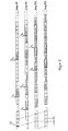
- the request for a connection so in the data insertion device DE from the terminal TE 1 the next possible empty packet by a packet "REQU 1" with a corresponding request to Network termination device NT replaced.
- the REQU 1 request package is completed by the functional groups E S , DE and S S of the subsequent terminals TE 2 and TE 3 are looped and thereby delayed by the running time ⁇ .
- the network termination device recognizes the connection request and at the time t2 by a packet "START 1" the request to send to the terminal TE 1.
- TE 1 begins at time t3 with the transmission of data packets "DATA 1", which in turn by the function groups E S , DE and S S can be ground.
- the START packets are also looped back to the network termination device NT.
- the start procedure for the terminal TE 2 takes place from t4 to t6.
- TE 1 signals the end of its transmission by means of a “STOP 1” packet.
- the temporal signal curve shown in FIG. 3 could give the impression that the terminals TE located at the end of the transmission bus SB are disadvantaged in terms of access to the latter. This is only correct with regard to a larger average delay when sending data packets.
- the general availability is guaranteed.
- the control in the network termination device NT has to be designed in such a way that only so many terminals TE are given permission to transmit that the sum of the data rates of all terminals TE in operation is somewhat smaller than the data rate on the ring line of the transmission bus SB. If this requirement is met, there are still enough empty packets available to synchronize the time multiple, even when the SB bus is fully loaded.
- the terminal TE 3 shown in somewhat more detail in the lower part of FIG. 2 illustrates the function of essential parts of a terminal TE.
- the data insertion device DE Provided that the terminal TE is in the operating state and an empty packet is detected by the data insertion device DE, the data insertion device DE outputs a control signal St to the device-internal packetizer, whereby from this with the obtained in E S ring line clock T is a data packet on the line SD to the data insertion apparatus DE is given. This puts the data packet in the place of the previously identified empty packet.
- the lines EB and SB can be designed as coaxial or as optical waveguide lines. In the latter case, additional electro-optical converters and a separate supply of the power supply are then required.
Landscapes
- Engineering & Computer Science (AREA)
- Computer Networks & Wireless Communication (AREA)
- Signal Processing (AREA)
- Small-Scale Networks (AREA)
Applications Claiming Priority (2)
| Application Number | Priority Date | Filing Date | Title |
|---|---|---|---|
| DE3710868 | 1987-04-01 | ||
| DE3710868 | 1987-04-01 |
Publications (3)
| Publication Number | Publication Date |
|---|---|
| EP0285154A2 true EP0285154A2 (fr) | 1988-10-05 |
| EP0285154A3 EP0285154A3 (fr) | 1991-09-25 |
| EP0285154B1 EP0285154B1 (fr) | 1994-06-15 |
Family
ID=6324571
Family Applications (1)
| Application Number | Title | Priority Date | Filing Date |
|---|---|---|---|
| EP88105236A Expired - Lifetime EP0285154B1 (fr) | 1987-04-01 | 1988-03-31 | Système de connexion de plusieurs terminaux à un dispositif de connexion de réseau dans un réseau à large bande |
Country Status (3)
| Country | Link |
|---|---|
| EP (1) | EP0285154B1 (fr) |
| JP (1) | JP2641487B2 (fr) |
| DE (1) | DE3850161D1 (fr) |
Cited By (3)
| Publication number | Priority date | Publication date | Assignee | Title |
|---|---|---|---|---|
| FR2647612A1 (fr) * | 1989-05-24 | 1990-11-30 | American Telephone & Telegraph | Dispositif, procede et reseau de transmission de donnees multipoint et multicanal |
| WO1999043129A1 (fr) * | 1998-02-23 | 1999-08-26 | Siemens Aktiengesellschaft | Systeme d'automatisation modulaire, procede pour faire fonctionner un systeme d'automatisation modulaire et systeme a bus pour appareils d'automatisation |
| EP0663786A3 (fr) * | 1993-12-14 | 1999-12-22 | KE KOMMUNIKATIONS-ELEKTRONIK GMBH & CO | Procédé de transmission de données numériques |
Family Cites Families (4)
| Publication number | Priority date | Publication date | Assignee | Title |
|---|---|---|---|---|
| JPS5336110A (en) * | 1976-09-16 | 1978-04-04 | Fujitsu Ltd | Data transfer system |
| ATE25906T1 (de) * | 1982-12-28 | 1987-03-15 | Ibm | Vielfachverbindungssystem fuer teilnehmerstationen. |
| US4627050A (en) * | 1984-05-22 | 1986-12-02 | Rolm Corporation | Time division multiplexed computerized branch exchange |
| US4641276A (en) * | 1984-10-22 | 1987-02-03 | General Electric Company | Serial-parallel data transfer system for VLSI data paths |
-
1988
- 1988-03-31 DE DE3850161T patent/DE3850161D1/de not_active Expired - Fee Related
- 1988-03-31 EP EP88105236A patent/EP0285154B1/fr not_active Expired - Lifetime
- 1988-04-01 JP JP63078291A patent/JP2641487B2/ja not_active Expired - Lifetime
Cited By (3)
| Publication number | Priority date | Publication date | Assignee | Title |
|---|---|---|---|---|
| FR2647612A1 (fr) * | 1989-05-24 | 1990-11-30 | American Telephone & Telegraph | Dispositif, procede et reseau de transmission de donnees multipoint et multicanal |
| EP0663786A3 (fr) * | 1993-12-14 | 1999-12-22 | KE KOMMUNIKATIONS-ELEKTRONIK GMBH & CO | Procédé de transmission de données numériques |
| WO1999043129A1 (fr) * | 1998-02-23 | 1999-08-26 | Siemens Aktiengesellschaft | Systeme d'automatisation modulaire, procede pour faire fonctionner un systeme d'automatisation modulaire et systeme a bus pour appareils d'automatisation |
Also Published As
| Publication number | Publication date |
|---|---|
| JP2641487B2 (ja) | 1997-08-13 |
| JPS63302641A (ja) | 1988-12-09 |
| EP0285154B1 (fr) | 1994-06-15 |
| DE3850161D1 (de) | 1994-07-21 |
| EP0285154A3 (fr) | 1991-09-25 |
Similar Documents
| Publication | Publication Date | Title |
|---|---|---|
| DE69128035T2 (de) | Verwaltungssystem von Zeitschlitzen | |
| DE4221474C2 (de) | Kommunikationssystem für Mehrdienste-Kommunikationsendeinrichtungen in lokalen Netzen | |
| DE69534813T2 (de) | Verfahren und Anordnung zur dynamischen Bandbreitenzuordnung in einem TDM/TDMA-Übertragungssystem | |
| DE2538638C2 (de) | Integriertes Nachrichtensystem | |
| DE19625901A1 (de) | Verfahren und Anordnungen zur optimalen Nutzung von vermittlungstechnischen und übertragungstechnischen Ressourcen von Multimedia-Kommunikationsnetzen | |
| DE3990712C2 (de) | Schnittstelleneinheit | |
| EP0110464B1 (fr) | Standard privé | |
| EP0017835A1 (fr) | Circuit pour commander la transmission de signaux digitaux, notamment signaux MIC, entre les points de raccordement d'un système de télécommunications à multiplexage par partage du temps, notamment d'un système MIC | |
| EP0202191A2 (fr) | Circuit pour un système de communication pour la transmission d'informations de message de terminaux à bande étroite et à large bande à l'intérieur de réseaux locaux en forme d'anneau | |
| EP0706292B1 (fr) | Circuit pour commander la transmission d'information de services interactifs | |
| EP0285154B1 (fr) | Système de connexion de plusieurs terminaux à un dispositif de connexion de réseau dans un réseau à large bande | |
| DE4008729C2 (fr) | ||
| DE3808413C1 (fr) | ||
| DE3438340A1 (de) | Anordnung zum anschliessen von endgeraeten und verfahren zum zuteilen von kanaelen an diese endgeraete | |
| DE2111706C3 (de) | Schaltungsanordnung für eine Fernsprech-Vermittlungsanlage mit Pulsphasenmodulation | |
| DE2546422C2 (de) | Zweidraht-Vollduplex-Datenübertragungsverfahren und Vorrichtung zur Ausführung des Verfahrens | |
| EP0018526B1 (fr) | Procédé pour faire fonctionner des terminaux principaux numériques et/ou des centraux privés reliés à un central de commutation MIC | |
| DE3215261C2 (fr) | ||
| EP0719047B1 (fr) | Méthode pour commander l'établissement des liaisons dans des services interactifs | |
| EP0006986A1 (fr) | Système de transmission de données, procédé de mise en oeuvre du dit système, et circuit pour le dit système | |
| DE3817407C2 (fr) | ||
| DE3808615C2 (fr) | ||
| EP0645908A2 (fr) | Procédé de multiplexage par partage du temps | |
| DE2517097A1 (de) | Verfahren zur nachrichtenuebertragung | |
| DE3643834A1 (de) | Verfahren zur bidirektionalen uebertragung von digitalsignalen |
Legal Events
| Date | Code | Title | Description |
|---|---|---|---|
| PUAI | Public reference made under article 153(3) epc to a published international application that has entered the european phase |
Free format text: ORIGINAL CODE: 0009012 |
|
| AK | Designated contracting states |
Kind code of ref document: A2 Designated state(s): DE FR GB |
|
| RAP1 | Party data changed (applicant data changed or rights of an application transferred) |
Owner name: N.V. PHILIPS' GLOEILAMPENFABRIEKEN Owner name: STANDARD ELEKTRIK LORENZ AKTIENGESELLSCHAFT Owner name: PHILIPS PATENTVERWALTUNG GMBH Owner name: SIEMENS AKTIENGESELLSCHAFT BERLIN UND MUENCHEN |
|
| 17P | Request for examination filed |
Effective date: 19901220 |
|
| PUAL | Search report despatched |
Free format text: ORIGINAL CODE: 0009013 |
|
| AK | Designated contracting states |
Kind code of ref document: A3 Designated state(s): DE FR GB |
|
| RAP3 | Party data changed (applicant data changed or rights of an application transferred) |
Owner name: N.V. PHILIPS' GLOEILAMPENFABRIEKEN Owner name: ALCATEL SEL AKTIENGESELLSCHAFT Owner name: PHILIPS PATENTVERWALTUNG GMBH Owner name: SIEMENS AKTIENGESELLSCHAFT |
|
| 17Q | First examination report despatched |
Effective date: 19930908 |
|
| GRAA | (expected) grant |
Free format text: ORIGINAL CODE: 0009210 |
|
| AK | Designated contracting states |
Kind code of ref document: B1 Designated state(s): DE FR GB |
|
| REF | Corresponds to: |
Ref document number: 3850161 Country of ref document: DE Date of ref document: 19940721 |
|
| GBT | Gb: translation of ep patent filed (gb section 77(6)(a)/1977) |
Effective date: 19940822 |
|
| ET | Fr: translation filed | ||
| PLBE | No opposition filed within time limit |
Free format text: ORIGINAL CODE: 0009261 |
|
| STAA | Information on the status of an ep patent application or granted ep patent |
Free format text: STATUS: NO OPPOSITION FILED WITHIN TIME LIMIT |
|
| 26N | No opposition filed | ||
| REG | Reference to a national code |
Ref country code: FR Ref legal event code: CD |
|
| PGFP | Annual fee paid to national office [announced via postgrant information from national office to epo] |
Ref country code: DE Payment date: 19980519 Year of fee payment: 11 |
|
| REG | Reference to a national code |
Ref country code: FR Ref legal event code: CD |
|
| PGFP | Annual fee paid to national office [announced via postgrant information from national office to epo] |
Ref country code: GB Payment date: 19990322 Year of fee payment: 12 |
|
| PGFP | Annual fee paid to national office [announced via postgrant information from national office to epo] |
Ref country code: FR Payment date: 19990330 Year of fee payment: 12 |
|
| PG25 | Lapsed in a contracting state [announced via postgrant information from national office to epo] |
Ref country code: DE Free format text: LAPSE BECAUSE OF NON-PAYMENT OF DUE FEES Effective date: 20000101 |
|
| PG25 | Lapsed in a contracting state [announced via postgrant information from national office to epo] |
Ref country code: GB Free format text: LAPSE BECAUSE OF NON-PAYMENT OF DUE FEES Effective date: 20000331 |
|
| GBPC | Gb: european patent ceased through non-payment of renewal fee |
Effective date: 20000331 |
|
| PG25 | Lapsed in a contracting state [announced via postgrant information from national office to epo] |
Ref country code: FR Free format text: LAPSE BECAUSE OF NON-PAYMENT OF DUE FEES Effective date: 20001130 |
|
| REG | Reference to a national code |
Ref country code: FR Ref legal event code: ST |