EP0285247B1 - Kontinuierlich betriebener und gereinigter Filterapparat - Google Patents
Kontinuierlich betriebener und gereinigter Filterapparat Download PDFInfo
- Publication number
- EP0285247B1 EP0285247B1 EP88301464A EP88301464A EP0285247B1 EP 0285247 B1 EP0285247 B1 EP 0285247B1 EP 88301464 A EP88301464 A EP 88301464A EP 88301464 A EP88301464 A EP 88301464A EP 0285247 B1 EP0285247 B1 EP 0285247B1
- Authority
- EP
- European Patent Office
- Prior art keywords
- air
- flow path
- filter screen
- hand
- air flow
- Prior art date
- Legal status (The legal status is an assumption and is not a legal conclusion. Google has not performed a legal analysis and makes no representation as to the accuracy of the status listed.)
- Expired
Links
- 239000002245 particle Substances 0.000 claims description 8
- 239000012535 impurity Substances 0.000 claims description 7
- 238000000034 method Methods 0.000 claims description 7
- 239000000356 contaminant Substances 0.000 claims description 6
- 238000011144 upstream manufacturing Methods 0.000 claims description 3
- 238000011010 flushing procedure Methods 0.000 claims description 2
- 230000004913 activation Effects 0.000 claims 1
- 230000001360 synchronised effect Effects 0.000 claims 1
- 229920000742 Cotton Polymers 0.000 description 6
- 238000004140 cleaning Methods 0.000 description 5
- 230000003750 conditioning effect Effects 0.000 description 2
- 238000001914 filtration Methods 0.000 description 2
- 239000012530 fluid Substances 0.000 description 2
- 239000002699 waste material Substances 0.000 description 2
- 208000007596 Byssinosis Diseases 0.000 description 1
- 230000008878 coupling Effects 0.000 description 1
- 238000010168 coupling process Methods 0.000 description 1
- 238000005859 coupling reaction Methods 0.000 description 1
- 239000000428 dust Substances 0.000 description 1
- 239000000835 fiber Substances 0.000 description 1
- 238000004519 manufacturing process Methods 0.000 description 1
- 201000003456 pulmonary hemosiderosis Diseases 0.000 description 1
Images

Classifications
-
- B—PERFORMING OPERATIONS; TRANSPORTING
- B01—PHYSICAL OR CHEMICAL PROCESSES OR APPARATUS IN GENERAL
- B01D—SEPARATION
- B01D46/00—Filters or filtering processes specially modified for separating dispersed particles from gases or vapours
- B01D46/42—Auxiliary equipment or operation thereof
- B01D46/44—Auxiliary equipment or operation thereof controlling filtration
- B01D46/446—Auxiliary equipment or operation thereof controlling filtration by pressure measuring
-
- B—PERFORMING OPERATIONS; TRANSPORTING
- B01—PHYSICAL OR CHEMICAL PROCESSES OR APPARATUS IN GENERAL
- B01D—SEPARATION
- B01D46/00—Filters or filtering processes specially modified for separating dispersed particles from gases or vapours
- B01D46/10—Particle separators, e.g. dust precipitators, using filter plates, sheets or pads having plane surfaces
-
- B—PERFORMING OPERATIONS; TRANSPORTING
- B01—PHYSICAL OR CHEMICAL PROCESSES OR APPARATUS IN GENERAL
- B01D—SEPARATION
- B01D46/00—Filters or filtering processes specially modified for separating dispersed particles from gases or vapours
- B01D46/42—Auxiliary equipment or operation thereof
- B01D46/4272—Special valve constructions adapted to filters or filter elements
-
- B—PERFORMING OPERATIONS; TRANSPORTING
- B01—PHYSICAL OR CHEMICAL PROCESSES OR APPARATUS IN GENERAL
- B01D—SEPARATION
- B01D46/00—Filters or filtering processes specially modified for separating dispersed particles from gases or vapours
- B01D46/42—Auxiliary equipment or operation thereof
- B01D46/44—Auxiliary equipment or operation thereof controlling filtration
- B01D46/46—Auxiliary equipment or operation thereof controlling filtration automatic
-
- B—PERFORMING OPERATIONS; TRANSPORTING
- B01—PHYSICAL OR CHEMICAL PROCESSES OR APPARATUS IN GENERAL
- B01D—SEPARATION
- B01D2273/00—Operation of filters specially adapted for separating dispersed particles from gases or vapours
- B01D2273/30—Means for generating a circulation of a fluid in a filtration system, e.g. using a pump or a fan
-
- Y—GENERAL TAGGING OF NEW TECHNOLOGICAL DEVELOPMENTS; GENERAL TAGGING OF CROSS-SECTIONAL TECHNOLOGIES SPANNING OVER SEVERAL SECTIONS OF THE IPC; TECHNICAL SUBJECTS COVERED BY FORMER USPC CROSS-REFERENCE ART COLLECTIONS [XRACs] AND DIGESTS
- Y02—TECHNOLOGIES OR APPLICATIONS FOR MITIGATION OR ADAPTATION AGAINST CLIMATE CHANGE
- Y02A—TECHNOLOGIES FOR ADAPTATION TO CLIMATE CHANGE
- Y02A50/00—TECHNOLOGIES FOR ADAPTATION TO CLIMATE CHANGE in human health protection, e.g. against extreme weather
- Y02A50/20—Air quality improvement or preservation, e.g. vehicle emission control or emission reduction by using catalytic converters
- Y02A50/2351—Atmospheric particulate matter [PM], e.g. carbon smoke microparticles, smog, aerosol particles, dust
Definitions
- the present invention is directed to air filters and more specifically to continuously operating air filters which are utilized to filter the particulate impurities from extremely contaminated air streams, and which are so constructed as to be continuously cleaned.
- the US-A-4,372,713 to Kean, Jr. is another example of the utilization of backwash air to clean bag-type filter apparatuses.
- the United States Patents Nos. US-A-1 , 493,110 to Deihl, US-A-1,729,527 to Titgen and US-A-4,502,874 to Levie et al are examples of systems in which two, substantially duplicate filter systems are alternatively used, one providing a cleaning function while the other is being cleaned. In such systems, the air paths and filter functions are generally separate and duplicated. Thus, such types of systems are relatively expensive.
- the Levie et al patent describes an apparatus which alternatively directs the fluid to be filtered to one or another of a plurality of filter compartments, each containing a filter medium. Sensing means are provided to sense the condition of filter clogging in the compartments, and diverting means are provided to divert the flow of fluid to a compartment having a relatively clean filter, when a clogging condition is sensed.
- a unitary housing and single, surface loading screen-type filter element are utilized in conjunction with a pair of movable vanes which alternately direct the air to one side section of the screen, then the other.
- the dirty air is directed to one side of the screen the opposite side section thereof is isolated therefrom and provided with a backwash of air pulled through the opposite side of the screen to remove the impurities there collected.
- the backwash air after serving its impurity flushing function, recirculates beneath the vanes and flows out through the system in a forward direction with the clean air.
- a filter housing having an air permeable filter screen intermediate the front and rear wall thereof forming a front intake chamber and a rear discharge chamber.
- a pair of air impermeable vanes pivotally mounted on opposite sides of a dirty air inlet in the front wall of the housing are swingable or movable between a first position where the vanes form a first conduit directing the dirty air toward the left-hand side of the filter member, and a second position where the vanes form a second conduit directing the dirty air toward the right-hand side of the filter member.
- a backwash air inlet is provided in confronting relationship with each side of the filter screen in the upper portion on the rear wall while discharge outlets corresponding to each side of the filter screen are provided in the lower portion of the rear wall.
- Dampers associated with each inlet and outlet operate in timed relation with the movement of the vanes to open the appropriate backwash air inlet at a prescribed time while the other remains closed and to control the opening of the clean air discharge outlets at the prescribed time in relation to vane movement.
- a particle collection receptacle is positioned below the intake chamber to receive contaminants flushed therefrom by the backwash air flow path.
- Control motors are connected to the vanes, backwash dampers, and discharge outlet dampers and are so electrically controlled that upon movement of the vanes to one side of the filter screen, and in a prescribed time sequence, the appropriate outlet and backwash damper open while the other outlet damper and backwash damper close.
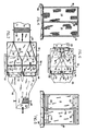
- An air treatment housing 10 receives return air from a delivery conduit 20 and discharges air through a discharge conduit 45 back into the plant air system.
- the housing 10 includes a front wall 12 having a rearwardly sloping lower port on 12a, a rear wall 14, a pair of side walls 16,18, and a top wall which has been removed in Figure 1 or the sake of illustration.
- the front wall includes a return air inlet 22 through which dirty air from conduit 20 passes into the interior of plenum housing 10.
- a filter screen 24 extends between side walls 16,18 and substantially from the top wall to a point contiguous with the lower edges of side walls 16,18 to divide the housing 10 into an intake chamber and a discharge chamber.
- a vertically extending, air impermeable divider plate 26 extends forwardly into the intake chamber from screen 24 along a juncture line approximately equidistant between the side walls 16,18 to divide the filter screen into a left-hand and right-hand section.
- a pair of vertically extending, air impermeable vanes 28,30 are pivotally mounted to front wall 12 by a pair of pivot pins or hinged connections 29,31 extending along opposite sides of the dirty air inlet 22. Vanes 28,30 are of sufficient length to engage the divider plate 26 when swung to the middle position to form the first or second conduits.
- the vanes 28,30 are of a vertical dimension less than the corresponding vertical dimension of side walls 16,18, front wall 12, and rear wall 14 for reasons to be described hereinafter.
- a pneumatic motor 32 ( Figures 3 and 6) is mounted on the top wall 15 of housing 10 and connected to vanes 28,30 by a linkage 34 so as to swing vanes 28,30 between a first position where the vane 28 engages the divider plate 26 and vane 30 engages the left side wall 16 to direct the dirty air toward the left-hand filter section and a second position where the vane 30 engages the divider plate 26 and vane 28 engages the right-hand side wall 18 to direct the dirty air toward the right-hand filter section (dotted lines 28 ⁇ ,30 ⁇ in Figure 2).
- a pressure relief filter 54 is placed in the lower portion of front wall 12 to relieve excessive pressures inside the intake chamber.
- the rear wall 14 includes upper left- and right-hand backwash air inlets 48,50 respectively.
- Dampers 52 selectively close backwash inlets 48,50 and are connected to pneumatic backwash motors 58,59 by means of operating levers.
- the timing is preferably such that when the vanes 28,30 move to the illustrated left-hand position, motor 58 immediately closes dampers 52 of left-hand inlet 48. Either simultaneously or at some time later motor 59 opens the dampers 52 of inlet 50 to admit backwash air.
- the dampers to inlets 48,50 also assume the reverse position.
- the lower portion of the rear wall 14 includes a left- and right-hand clean air discharge outlet 40,42 respectively.
- Outlets 40,42 also are selectively closed and opened by dampers 44 preferably connected to and operated by a single pneumatic damper motor 60 through a coupling linkage 61.
- a first suction fan 80 is so arranged as to pull air from the interior of the air treatment housing or plenum 10 at volumes of preferably 1 ⁇ 65m3s ⁇ 1-1 ⁇ 89m3s ⁇ 1 (3500-4000 c.f.m).
- a second blower or fan 82 is positioned in the air delivery conduit 20 upstream of front wall 12 which pushes air into the housing 10 at rates of approximately 1 ⁇ 18m3s ⁇ 1-1 ⁇ 41m3s ⁇ 1 (2500-3000 c.f.m).
- Sloped lower edge 12a extends downwardly from the lower edges of front wall 12 to guide waste particles, removed from screen 24 by the backwash air currents, through the open bottom of housing 10.
- the waste particles may be collected beneath housing in some type of baler 56; they may be transferred to another location by some type of screw or worm conveyor; or other disposition thereof may be made.
- the housing or plenum is approximately 1 ⁇ 77m (seventy inches) high (excluding hopper 54), 1 ⁇ 47m (fifty-eight inches) from front to rear, and 1 ⁇ 52m (sixty inches) wide.
- the vanes are approximately 1 ⁇ 32m (fifty-two inches) in height leaving a space of approximately 0 ⁇ 46m (eighteen inches) therebeneath for the passage of backwash air currents to return through the screen in a forward direction. This 0 ⁇ 46m (eighteen inch) space allows the circulation of backwash air without creating disturbing air currents in hopper 54.
- the dirty air inlet 22 in front wall 12 is 0 ⁇ 15m (six inches) by 0 ⁇ 71m (twenty-eight inches) and located approximately centrally from side to side and in the upper portion of the front wall 12.
- Each of the backwash inlets and clean air discharge outlets are referable 0 ⁇ 3m (twelve inches) by 0 ⁇ 6m (twenty-four inches).
- Screen 24 is preferably seventy mesh (2756 openings per meter (seventy openings per inch) vertically and horizontally).
- the suction fan 80 draws approximately 1 ⁇ 65m3s ⁇ 1-1 ⁇ 89m3s ⁇ 1 (3500-4000 c.f.m.) from within the housing 10 and the return air system, schematically represented by blower 82, delivers approximately 1 ⁇ 18m3s ⁇ 1-1 ⁇ 41m3s ⁇ 1 (2500-3000 c.f.m.) into the housing 10 through front wall 12.
- Fan 80 produces a vacuum volume of 1 ⁇ 65m3s ⁇ 1-1 ⁇ 89m3s ⁇ 1 (3500-4000 c.f.m) from within the housing and blower 82 will be delivering 1 ⁇ 18m3s ⁇ 1-1 ⁇ 41m3s ⁇ 1 (2500-3000 c.f.m) of replacement air into the housing 10 and on through the left-hand portion of screen 24.
- a backwash air flow of 0 ⁇ 47m3s ⁇ 1 (1000 c.f.m.) is thus induced through inlet 50 and is drawn through the back side of screen 24 in a reverse direction thus tending to blow or flush the trapped particles collected on the dirty or front side thereof.
- the particles drop into collector receptacle 56 while the backwash air flow path continues down beneath vane 28 back through the left-hand portion of screen 24 and out through the discharge opening 40 along with the other clean air.
- vane motor 32 When the pressure sensitive switch PS1, which includes a first pressure sensor in the discharge chamber and a second pressure sensor in the intake chamber to measure pressure drop across screen 24, indicates a prescribed buildup of contaminating particles on the dirty side of screen 24, vane motor 32 will be activated to move the vanes 28,30 to the second position directing the air to the right-hand section of screen 24. Either simultaneously with or after a prescribed time lapse, dampers 52 will reverse to open inlet 48 and close inlet 50. Also, motor 60 will be activated to reverse the dampers 44 causing the discharge outlet 42 to be open while discharge outlet 40 is closed. The filter operation is continued until the right-hand filter screen section becomes clogged to the prescribed level, whereupon the vanes and dampers are again reversed.
Landscapes
- Chemical & Material Sciences (AREA)
- Chemical Kinetics & Catalysis (AREA)
- Filtering Of Dispersed Particles In Gases (AREA)
Claims (10)
- Vorrichtung zum unterbrechungsfreien Abscheiden von verunreinigenden Partikeln aus einem Luftstrom bei gleichzeitigem unterbrechungsfreiem Reinigungsvorgang, mit:(a) Mitteln (20 82) zum Erzeugen eines ersten vorwärtsgerichteten Luftstromwegs, der partikelförmige Verunreinigungen enthält;(b) einem luftdurchlässigen Filtersieb (24) mit einem linken und einem rechten Abschnitt, die in dem Luftstrom angeordnet sind;(c) beweglichen luftundurchlässigen Leitklappenmitteln (28, 30) um den Luftstromweg entweder durch den linken oder den rechten Abschnitt des Filtersiebs (24) zu führen;(d) in Abhängigkeit von der Bewegung der Leitklappenmittel (28, 30) betriebene Rückspülmittel (48, 50), um einen strömungsweg für Reinigungsluft in einer entgegengesetzten Richtung durch den linken oder den rechten Abschnitt des Siebs (24) zu richten, der jeweils verschieden von dem ist, durch den der erste, vorwärtsgerichtete Luftstromweg führt.
- Vorrichtung nach Anspruch 1, bei der die Mittel (20, 82) zum Erzeugen eines ersten Luftstromwegs einen Lufteinlaß (20) auf der stromaufwärts liegenden Seite des Filtersiebs (24) zum Einleiten von Luftströmen zwischen die Leitklappenmittel (28, 30) und gegen den oberen Abschnitt des Filtersiebs (24), auf der stromabwärts liegenden Seite des Filtersiebs (24) einen linken und einen rechten Auslaß (40, 42), wobei die Auslässe (40, 42) gegenüber dem unteren Abschnitt des Filtersiebs (24) und im Abstand zu diesem angeordnet sind, sowie eine Ansaugeinrichtung (80) umfassen, die stromabwärts von den Auslässen (40, 42) liegt und mit diesen strömungsmäßig in Verbindung steht, wobei der erste durch das Sieb (24) führende Luftstromweg veranlaßt wird, abwärts und nach außen durch die entsprechenden Auslässe (40, 42) zu strömen.
- Vorrichtung nach Anspruch 2, bei der jeder der Auslässe (40, 42) mit einem Verschlußklappenmittel (44) zum wahlweisen Öffnen und Schließen der Auslässe (40, 42) sowie mit Antriebsmitteln (60) zum Betätigen des Verschlußklappenmittels (44) eines jeden Auslasses (40, 42) in gegenphasig synchroner Beziehung zu dem anderen versehen ist.
- Vorrichtung nach Anspruch 3, bei der die Mittel zum Erzeugen des zweiten Luftstroms einen linken und einen rechten Lufteinlaß (48, 50) an der stromabwärts liegenden Seite des Filtersiebs (24) umfassen, der linke und der rechte Lufteinlaß (48, 50) gegenüber dem oberen Abschnitt des Filtersiebs (24) und von diesem im Abstand angeordnet sind, wobei die Unterdruckquelle (80) Luft von dem linken und dem rechten Einlaß (48, 50) in einer entgegengesetzten Richtung durch das Filtersieb (24) saugt, um die darauf befindlichen Verunreinigungen zu entfernen, und der zweite Luftstrom sodann mit dem ersten Luftstrom vereinigt wird und weiter durch das Sieb (24) in einer vorwärtsgerichteten Richtung und durch einen der Auslässe (40, 42) strömt.
- Vorrichtung nach einem der Ansprüche 1 bis 4, bei der dem Filtersieb (24) ein Differenzdruckschalter (PS1) zugeordnet ist, der mit Drucksensoren an der stromaufwärts liegenden und der stromabwärts liegenden Seite des linken und des rechten Abschnitts des Filtersiebs (24) verbunden ist und von diesen gesteuert wird, und die mit einem Antriebsmittel (32) zum Bewegen der Leitklappenmittel (28, 30) von einer ersten Stellung, in der diese Luft durch einen ersten Abschnitt des Filtersiebs (24) leiten, in eine zweite Stellung, in der diese Luft durch einen zweiten Abschnitt des Filtersiebs (24) leiten, versehen ist, das in Abhängigkeit von einem aus den entsprechenden Drucksensoren kommenden Signal, das anzeigt, daß das Filtersieb mit teilchenförmigen Verunreinigungen bis zu einem bestimmten Grad beladen ist, arbeitet.
- Vorrichtung nach Anspruch 4 oder 5, bei der sowohl der linke als auch der rechte Lufteinlaß (48, 50) für den zweiten Luftstromweg mit einem Verschlußklappenmittel (52) zum wahlweisen Öffnen oder Schließen desselben sowie mit Antriebsmitteln (59) zum Betätigen des Verschlußklappenmittels (52) eines jeden Lufteinlasses (48, 50) in einer zeitlichen Beziehung zu dem Leitklappenmotor (32) versehen ist.
- Vorrichtung nach Anspruch 6, bei der die Antriebsmittel (60) für die Auslaßverschlußklappen und die Antriebsmittel (59) für die Einlaßverschlußklappen in einer zeitlichen Abfolge in Abhängigkeit von der Betätigung der Leitklappenantriebsmittel (32) betätigt werden.
- Verfahren zum unterbrechungsfreien Abtrennen von verunreinigenden Teilchen aus einem Luftstrom bei gleichzeitiger unterbrechungsfreier Reinigung, das die folgenden Schritte umfaßt:(a) Erzeugen eines ersten, teilchenförmige Verunreinigungen enthaltenden, vorwärtsgerichteten Luftstromwegs zu einem Filtersieb;(b) Ablenken des ersten Luftstromwegs entweder durch einen linken oder durch einen rechten Abschnitt des Filtersiebs;(c) Führen eines zweiten spülenden Luftstromwegs in einer umgekehrten Richtung entweder durch den linken oder den rechten Abschnitt des Siebs, gegenüber demjenigen Abschnitt, durch den der erste Luftstrom sich in Vorwärtsrichtung bewegt.
- Verfahren nach Anspruch 8, bei dem der Schritt (c) in einem zeitlich abgestimmt zu dem Ablenken des ersten Luftstromwegs erfolgt.
- Verfahren nach Anspruch 8 oder 9, bei dem der zweite Luftstrom, nachdem er in entgegengesetzter Richtung durch das Sieb hindurchgetreten ist, mit dem ersten Luftstrom zusammengeführt und mit diesem vermischt wird, und dann durch den gegenüberliegenden Abschnitt des Siebs in Vorwärtsrichtung hindurchtritt.
Applications Claiming Priority (2)
| Application Number | Priority Date | Filing Date | Title |
|---|---|---|---|
| US07/033,652 US4778491A (en) | 1987-04-03 | 1987-04-03 | Continuously operated and cleaned filter apparatus |
| US33652 | 1987-04-03 |
Publications (2)
| Publication Number | Publication Date |
|---|---|
| EP0285247A1 EP0285247A1 (de) | 1988-10-05 |
| EP0285247B1 true EP0285247B1 (de) | 1992-12-09 |
Family
ID=21871653
Family Applications (1)
| Application Number | Title | Priority Date | Filing Date |
|---|---|---|---|
| EP88301464A Expired EP0285247B1 (de) | 1987-04-03 | 1988-02-22 | Kontinuierlich betriebener und gereinigter Filterapparat |
Country Status (5)
| Country | Link |
|---|---|
| US (1) | US4778491A (de) |
| EP (1) | EP0285247B1 (de) |
| JP (1) | JPS63264116A (de) |
| CA (1) | CA1314495C (de) |
| DE (1) | DE3876468T2 (de) |
Families Citing this family (39)
| Publication number | Priority date | Publication date | Assignee | Title |
|---|---|---|---|---|
| US4895581A (en) * | 1989-04-12 | 1990-01-23 | Pneumafil Corporation | Two stage air filtration system |
| GB2258828B (en) * | 1991-08-16 | 1995-02-22 | Btr Plc | Filter assembly |
| US5174797A (en) * | 1991-09-12 | 1992-12-29 | Industrial Air, Inc. | Fiber collector |
| US5279629A (en) * | 1993-02-26 | 1994-01-18 | Ltg Lufttechnische Gmbh | Air handling apparatus and method for textile machines |
| CA2126802C (en) * | 1994-06-27 | 1999-08-17 | Hermann Ophardt | Powder paint booth backflow filter apparatus |
| US5647889A (en) * | 1994-06-28 | 1997-07-15 | Ltg Lufttechnische Gmbh | Air handling apparatus and method for textile machines |
| US5709721A (en) * | 1996-01-31 | 1998-01-20 | Ltg Technologies, Inc. | Air handling apparatus for textile machines |
| DE19908377A1 (de) * | 1999-02-26 | 2000-08-31 | Schlafhorst & Co W | Filtereinrichtung für eine Kreuzspulen herstellende Textilmaschine |
| US6146433A (en) * | 1999-05-11 | 2000-11-14 | Venturedyne, Ltd. | Internal air baffle |
| DE10214389A1 (de) * | 2002-03-30 | 2003-10-16 | Truetzschler Gmbh & Co Kg | Vorrichtung in der Spinnereivorbereitung zum Abscheiden der Transportluft beim Beschicken von Fasermaterial, z.B. Baumwolle o. dgl., zu einer Verarbeitungsmaschine |
| US6890365B2 (en) | 2003-05-09 | 2005-05-10 | Dillman Equipment, Inc. | Reverse-flow baghouse |
| US7438735B2 (en) * | 2004-02-27 | 2008-10-21 | Eastman Kodak Company | Filter apparatus with automatic cleaning |
| US7479170B1 (en) * | 2004-09-01 | 2009-01-20 | Collette Jerry R | Modular up-draft pressure pulse bag house |
| TWI247190B (en) * | 2004-11-09 | 2006-01-11 | Coretronic Corp | Self dust-off apparatus and method thereof |
| SG10201505988SA (en) | 2005-08-09 | 2015-09-29 | Camfil Usa Inc | Integrated containment system |
| DE102008011763A1 (de) * | 2008-02-28 | 2009-09-03 | Oerlikon Textile Gmbh & Co. Kg | Filtereinrichtung für eine Textilmaschine |
| CN105854488A (zh) * | 2016-05-28 | 2016-08-17 | 周末 | 一种公路汽车尾气吸收净化装置 |
| CN105833650A (zh) * | 2016-05-28 | 2016-08-10 | 周末 | 一种烟尘净化设备 |
| CN105854487A (zh) * | 2016-05-28 | 2016-08-17 | 周末 | 一种化工厂废气净化处理装置 |
| CN105833613A (zh) * | 2016-06-10 | 2016-08-10 | 成都恒力达科技有限公司 | 一种废气过滤净化系统 |
| CN105833614A (zh) * | 2016-06-10 | 2016-08-10 | 成都恒力达科技有限公司 | 一种化工企业废气净化处理器 |
| CN105833622A (zh) * | 2016-06-10 | 2016-08-10 | 成都恒力达科技有限公司 | 一种高效环保的降低化工企业废气污染的装置 |
| CN105854440B (zh) * | 2016-06-12 | 2018-03-23 | 盐城远东化工有限公司 | 一种工业废气过滤净化器 |
| CN105879554B (zh) * | 2016-06-12 | 2018-03-27 | 浙江裕文环保科技有限公司 | 一种空气净化设备 |
| CN105833615A (zh) * | 2016-06-12 | 2016-08-10 | 成都恒力达科技有限公司 | 一种空气过滤净化装置 |
| CN105854497B (zh) * | 2016-06-12 | 2018-04-06 | 江苏万贤环境工程有限公司 | 一种工业废气净化装置 |
| CN106110810B (zh) * | 2016-07-17 | 2018-02-23 | 广东安联机电有限公司 | 一种废气过滤处理系统 |
| CN105999966B (zh) * | 2016-07-17 | 2018-08-31 | 广东美集世智能科技有限公司 | 一种对燃烧产生废气的过滤净化系统 |
| CN105964097B (zh) * | 2016-07-17 | 2018-05-11 | 上海古蓝环境工程有限公司 | 一种对废弃物燃烧产生废气的处理系统 |
| CN106310856A (zh) * | 2016-09-30 | 2017-01-11 | 成都冠禹科技有限公司 | 一种室内空气净化除尘装置 |
| CN106362526A (zh) * | 2016-09-30 | 2017-02-01 | 成都冠禹科技有限公司 | 一种空气分级过滤净化系统 |
| EP3558723B1 (de) * | 2016-12-23 | 2023-08-02 | Hubtech Holding B.V. | Fahrzeugrad, insbesondere fahrradrad, nabe für solch ein rad und mit solch einem rad ausgestattetes fahrzeug |
| CN109881558A (zh) * | 2019-04-19 | 2019-06-14 | 江苏建筑职业技术学院 | 地面铺设结构、铺设方法及处理方法 |
| CN111558258A (zh) * | 2019-11-14 | 2020-08-21 | 佛山科学技术学院 | 一种基于大气污染治理的空气净化装置 |
| DE102020113494A1 (de) * | 2020-05-19 | 2021-11-25 | Saurer Spinning Solutions Gmbh & Co. Kg | Filtereinrichtung für eine Kreuzspulen herstellende Textilmaschine |
| CN114100267B (zh) * | 2021-11-26 | 2023-03-14 | 广州市万保职业安全事务有限公司 | 一种机床免换网气体过滤装置 |
| DE102022106192A1 (de) | 2022-03-16 | 2023-09-21 | Trützschler Group SE | Spinnereianlage mit einer Filtervorrichtung |
| CN116116099A (zh) * | 2023-03-09 | 2023-05-16 | 四川省生态环境科学研究院 | 一种环保型废水过滤收集装置 |
| CN116025612B (zh) * | 2023-03-27 | 2023-06-20 | 烟台中宇航空液压有限公司 | 一种回转式电液伺服阀 |
Family Cites Families (16)
| Publication number | Priority date | Publication date | Assignee | Title |
|---|---|---|---|---|
| US1729527A (en) * | 1926-08-04 | 1929-09-24 | Harry W Titgen | Dust collector |
| GB546878A (en) * | 1941-12-11 | 1942-08-04 | Thomas Ash & Company Ltd | Improvements in or relating to dust-extracting or filtering apparatus |
| GB778537A (en) * | 1955-01-26 | 1957-07-10 | Kloeckner Humboldt Deutz Ag | Improvements in gas filters |
| US3164455A (en) * | 1961-06-29 | 1965-01-05 | American Air Filter Co | Air cleaning apparatus |
| GB1095904A (en) * | 1965-11-17 | 1967-12-20 | Parks Cramer Ltd | Improvements relating to air filtering apparatus |
| GB1218975A (en) * | 1968-05-29 | 1971-01-13 | Central Electr Generat Board | Improvements in or relating to self-cleaning strainers |
| US3612616A (en) * | 1969-04-04 | 1971-10-12 | Parks Cramer Ltd | Textile machine fiber waste disposal system |
| US3627584A (en) * | 1969-06-10 | 1971-12-14 | Parks Cramer Ltd | Method for pneumatically cleaning open-end spinning machines |
| US3699747A (en) * | 1969-09-08 | 1972-10-24 | Gert Kroll | Process for cleaning filter elements of fabric filter equipment |
| US3951623A (en) * | 1971-11-23 | 1976-04-20 | Ltg Lufttechnische Gmbh | Method of and apparatus for cleaning filter boxes |
| US4036614A (en) * | 1975-03-21 | 1977-07-19 | Nfe International, Ltd. | Pressure relief means for industrial vacuum |
| DE2829683A1 (de) * | 1978-07-06 | 1980-01-24 | Heinz Hoelter | Zweikammerfilter, vorzugsweise fuer den bergbau |
| US4372713A (en) * | 1980-10-03 | 1983-02-08 | Process Control Corporation | Bulk material receiver |
| AT375422B (de) * | 1982-07-07 | 1984-08-10 | Andritz Ag Maschf | Einrichtung zur reinigung der luftfilter in zufuehrungskanaelen fuer trocknungsluft |
| US4502874A (en) * | 1982-10-08 | 1985-03-05 | Pneumafil Corporation | Continuous filtration |
| US4560396A (en) * | 1984-08-20 | 1985-12-24 | Allis-Chalmers Corporation | Down flow filter panel dust collector |
-
1987
- 1987-04-03 US US07/033,652 patent/US4778491A/en not_active Expired - Lifetime
-
1988
- 1988-02-16 CA CA000558959A patent/CA1314495C/en not_active Expired - Fee Related
- 1988-02-22 EP EP88301464A patent/EP0285247B1/de not_active Expired
- 1988-02-22 DE DE8888301464T patent/DE3876468T2/de not_active Expired - Fee Related
- 1988-03-25 JP JP63071730A patent/JPS63264116A/ja active Pending
Also Published As
| Publication number | Publication date |
|---|---|
| JPS63264116A (ja) | 1988-11-01 |
| EP0285247A1 (de) | 1988-10-05 |
| DE3876468D1 (de) | 1993-01-21 |
| US4778491A (en) | 1988-10-18 |
| DE3876468T2 (de) | 1993-04-22 |
| CA1314495C (en) | 1993-03-16 |
Similar Documents
| Publication | Publication Date | Title |
|---|---|---|
| US4778491A (en) | Continuously operated and cleaned filter apparatus | |
| EP0793438B1 (de) | Filteranordnung für einen staubsauger | |
| US3486309A (en) | Fiber waste disposal system for textile machines | |
| US3870489A (en) | Air filter systems for debris collecting apparatus | |
| US4222754A (en) | High efficiency filter for textile waste | |
| US3612616A (en) | Textile machine fiber waste disposal system | |
| US5217509A (en) | Filtration system | |
| CA2314637C (en) | Dustless regenerative.rtm. air sweeper | |
| US5174797A (en) | Fiber collector | |
| US5120333A (en) | Recycling system for industrial vacuum machine | |
| CN107008074A (zh) | 一种带在线检测系统的布袋除尘器 | |
| CA2014404C (en) | Two stage air filtration system | |
| US5171338A (en) | Gas filter installation with improved unclogging means | |
| US5405421A (en) | Gas stream filtering system using filtered gas for reverse flow cleaning | |
| US4461633A (en) | Air filtering machinery with variable speed cleaning | |
| GB2270334A (en) | Pneumatic refuse collection and filter apparatus for a roadsweeper | |
| US5571299A (en) | Dust collector | |
| KR910004125B1 (ko) | 분말회수장치 | |
| US6010561A (en) | Vacuum cleaner and a filter assembly therefor | |
| CZ345398A3 (cs) | Přístroj pro domovní filtr s vaky | |
| JP2746785B2 (ja) | バグフィルタの洗浄方法 | |
| JP3325525B2 (ja) | バグフィルタ装置 | |
| US4134745A (en) | Air cleaning apparatus | |
| SU654704A1 (ru) | Устройство дл сбора угаров чесальных машин | |
| EP1488841A1 (de) | Vorrichtung zur kontinuierlichen entfernung von staub aus angesaugten gasen |
Legal Events
| Date | Code | Title | Description |
|---|---|---|---|
| PUAI | Public reference made under article 153(3) epc to a published international application that has entered the european phase |
Free format text: ORIGINAL CODE: 0009012 |
|
| AK | Designated contracting states |
Kind code of ref document: A1 Designated state(s): AT BE CH DE ES FR GB GR IT LI LU NL SE |
|
| 17P | Request for examination filed |
Effective date: 19890328 |
|
| 17Q | First examination report despatched |
Effective date: 19910328 |
|
| GRAA | (expected) grant |
Free format text: ORIGINAL CODE: 0009210 |
|
| AK | Designated contracting states |
Kind code of ref document: B1 Designated state(s): DE GB |
|
| REF | Corresponds to: |
Ref document number: 3876468 Country of ref document: DE Date of ref document: 19930121 |
|
| EN | Fr: translation not filed | ||
| PLBE | No opposition filed within time limit |
Free format text: ORIGINAL CODE: 0009261 |
|
| STAA | Information on the status of an ep patent application or granted ep patent |
Free format text: STATUS: NO OPPOSITION FILED WITHIN TIME LIMIT |
|
| 26N | No opposition filed | ||
| PGFP | Annual fee paid to national office [announced via postgrant information from national office to epo] |
Ref country code: DE Payment date: 19950303 Year of fee payment: 8 |
|
| PGFP | Annual fee paid to national office [announced via postgrant information from national office to epo] |
Ref country code: GB Payment date: 19950321 Year of fee payment: 8 |
|
| PG25 | Lapsed in a contracting state [announced via postgrant information from national office to epo] |
Ref country code: GB Effective date: 19960222 |
|
| GBPC | Gb: european patent ceased through non-payment of renewal fee |
Effective date: 19960222 |
|
| PG25 | Lapsed in a contracting state [announced via postgrant information from national office to epo] |
Ref country code: DE Effective date: 19961101 |