EP0285300A1 - Elément de friction pour embrayage - Google Patents
Elément de friction pour embrayage Download PDFInfo
- Publication number
- EP0285300A1 EP0285300A1 EP88302476A EP88302476A EP0285300A1 EP 0285300 A1 EP0285300 A1 EP 0285300A1 EP 88302476 A EP88302476 A EP 88302476A EP 88302476 A EP88302476 A EP 88302476A EP 0285300 A1 EP0285300 A1 EP 0285300A1
- Authority
- EP
- European Patent Office
- Prior art keywords
- friction
- facing
- friction facing
- lobes
- friction element
- Prior art date
- Legal status (The legal status is an assumption and is not a legal conclusion. Google has not performed a legal analysis and makes no representation as to the accuracy of the status listed.)
- Ceased
Links
Images

Classifications
-
- F—MECHANICAL ENGINEERING; LIGHTING; HEATING; WEAPONS; BLASTING
- F16—ENGINEERING ELEMENTS AND UNITS; GENERAL MEASURES FOR PRODUCING AND MAINTAINING EFFECTIVE FUNCTIONING OF MACHINES OR INSTALLATIONS; THERMAL INSULATION IN GENERAL
- F16D—COUPLINGS FOR TRANSMITTING ROTATION; CLUTCHES; BRAKES
- F16D69/00—Friction linings; Attachment thereof; Selection of coacting friction substances or surfaces
- F16D69/04—Attachment of linings
- F16D69/0408—Attachment of linings specially adapted for plane linings
-
- F—MECHANICAL ENGINEERING; LIGHTING; HEATING; WEAPONS; BLASTING
- F16—ENGINEERING ELEMENTS AND UNITS; GENERAL MEASURES FOR PRODUCING AND MAINTAINING EFFECTIVE FUNCTIONING OF MACHINES OR INSTALLATIONS; THERMAL INSULATION IN GENERAL
- F16D—COUPLINGS FOR TRANSMITTING ROTATION; CLUTCHES; BRAKES
- F16D13/00—Friction clutches
- F16D13/58—Details
- F16D13/60—Clutching elements
- F16D13/64—Clutch-plates; Clutch-lamellae
-
- F—MECHANICAL ENGINEERING; LIGHTING; HEATING; WEAPONS; BLASTING
- F16—ENGINEERING ELEMENTS AND UNITS; GENERAL MEASURES FOR PRODUCING AND MAINTAINING EFFECTIVE FUNCTIONING OF MACHINES OR INSTALLATIONS; THERMAL INSULATION IN GENERAL
- F16D—COUPLINGS FOR TRANSMITTING ROTATION; CLUTCHES; BRAKES
- F16D69/00—Friction linings; Attachment thereof; Selection of coacting friction substances or surfaces
-
- F—MECHANICAL ENGINEERING; LIGHTING; HEATING; WEAPONS; BLASTING
- F16—ENGINEERING ELEMENTS AND UNITS; GENERAL MEASURES FOR PRODUCING AND MAINTAINING EFFECTIVE FUNCTIONING OF MACHINES OR INSTALLATIONS; THERMAL INSULATION IN GENERAL
- F16D—COUPLINGS FOR TRANSMITTING ROTATION; CLUTCHES; BRAKES
- F16D69/00—Friction linings; Attachment thereof; Selection of coacting friction substances or surfaces
- F16D69/04—Attachment of linings
- F16D2069/0425—Attachment methods or devices
- F16D2069/0433—Connecting elements not integral with the braking member, e.g. bolts, rivets
Definitions
- This invention relates to a friction element for use in a friction clutch.
- Friction elements of the kind to which the invention relates are used connected to a clutch hub member to form the driven element of a type of friction clutch widely used, for example, in the drive lines of heavy duty motor vehicles.
- a typical clutch driven element has a plurality of friction elements disposed about the circumference of a clutch hub member, each friction element having a friction facing engagable with a driving element of the clutch.
- the friction facing may be of sintered metallic and/or ceramic material, and many shapes have been proposed for such friction facings. Viewed in the direction parallel to the rotational axis of the clutch hub member, the shape of most friction facings has been a portion of an annulus of the material.
- the speed at which rubbing occurs at the surface of a friction facing is greater at a greater distance from the axis of rotation of the clutch disc, so that there is a greater generation of heat and tendency for the friction material to wear at such greater distance.
- the amount of friction material at portions thereof where the rubbing speed is greater must be greater than that where the speed is less.
- a friction element comprising a backing plate for mounting to a clutch hub member to be rotatable in use about an axis and a friction facing provided on said backing plate, said friction facing being of a generally trefoil configuration and comprising a first radially inwardly extending lobe and second and third lobes extending radially outwardly and in opposite circumferential directions from said first lobe.
- Such a shape of the friction facing on the friction element is economical in use of the friction material, and yet meets the fundamental requirement of providing a greater quantity of material at a radially outer position.
- a further advantage of a friction element according to the invention is that the three lobes of the friction facing can be considered as having individual centres of area which are relatively widely spaced from one another on the backing plate.
- the pressure plate When engaged by a pressure plate under the action of a spring in a clutch, the pressure plate is supported by the friction facing at regions which are relatively widely spaced on the pressure plate.
- the pressure plate is well supported around its circumferentially extending region which contacts the friction facings, without any relatively large areas of pressure plate left unsupported.
- friction facings of simpler configuration than the three-lobed shape according to the present invention could provide the same total area of friction facing, and meet the requirement for increasing circumferential extent with increasing radius, such shapes would leave larger parts of the pressure plate unsupported between the friction elements, leading to the possibility of distortion of the pressure plate.
- the shape of the friction facing according to the invention thus provides a beneficial distribution of material in terms of circumferential extent relative to radial distance from the axis of rotation of the clutch disc, consistent with good support of the pressure plate as above described.
- the dimension of the friction facing measured on arcuate lines centered on the axis of rotation of the clutch hub member in use increases generally linearly within increasing distances of said lines from said axis.
- edges of the friction facing which face generally circumferentially and are the leading the trailing edges when the friction element is in use, are of curved concave configuration.
- the radially outwardly facing, circumferentially extending edge of the friction facing is curved and concave between said second and third lobes of the friction facing.
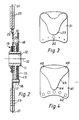
- FIG. 1 and 2 of the drawings there is shown a clutch driven element which is intended for rotation about at axis 10.
- the central part or hub assembly of the clutch driven element is of a construction generally known for such elements, comprising a hub 11 with an internally splined bore 12 to be received on a splined shaft for torque transmission therewith.
- a flange 13 extends outwardly from the hub 11, and lies between and spaced from two axially spaced plates 14, 15 which are held together by circumferentially spaced rivets 16 passing through spacer sleeves 17.
- the hub 11 and the plates 14, 15 are capable of limited rotational movement relative to one another, this movement being controlled by circumferentially spaced springs 18 occupying aligned pockets in the plates 14, 15 and flange 13, such movement being damped by friction elements as generally indicated at 19 in the region of the hub 11.
- This is a generally known construction for the hub and associated parts of a clutch driven plate.
- the plate 14 is provided with three circumferentially spaced friction element assemblies, indicated generally at 20. Each comprises a backing plate 21 held to the plate 14 by circumferentially spaced rivets 22.
- the backing plate is provided with two friction facings 23 on each side thereof.
- Each friction facing is preferably of a sintered metallic and/or ceramic material such as is generally known for use as friction facings, and is secured to the backing plate by being brazed thereto as part of the sintering process for its manufacture.
- Such a manufacturing process is generally known for such materials and friction facings, comprising broadly the process of forming the friction facing in the "green" state on the backing plate, and then sintering it in a suitable furnace.
- Each friction facing 23 is of a trefoil shape, comprising (as described with reference to one of the facings) a first portion in the form of a lobe 24 which extends radially inwardly towards the axis of rotation of the clutch and second and third portions in the form of lobes 25, 26 which extend radially outwardly and circumferentially away from one another. Between the lobes 25, 26 the circumferentially extending, outwardly facing, edge of the friction facing presents a concave portion 27.
- Each of the lobes 24, 25, 26 has a rounded end portion, the radially innermost end of the lobe 24 being of somewhat larger radius than the outer end portions of the lobes 25, 26.
- the generally radially extending, circumferentially facing, edges 28 of the friction facing between the lobes 24, 25 and at 26 are concave.
- the shape of the friction facing gives an approximately linear increase in the circumferential extent of the facing, measured along these lines, with increasing radial distance from the axis of rotation 10.
- the circumferential extent of the friction facing comprises two portions where the lobes 25, 26 are intersected by the line.
- the shape of the friction facing meets the above described desirable characteristic of having a circumferential extent which increases approximately linearly with distance from the axis or rotation of the clutch plate.
- This relationship applies only over the major part of the radial extent of the friction facing, since it is clearly not applicable at the extreme ends of the lobes 24, 25, 26.
- the rounded ends of these lobes have the effect that the friction facing is relatively robust, with no portions thereof unsupported by adjacent portions, so that the friction facing is not likely to break up or have parts become detached therefrom, either during manufacture or in use.
- the configuration of the friction facing has the effect, as above described, that in a clutch the pressure plate is well supported.
- FIG. 3 of the drawings there is shown a modified form of friction element.
- This comprises a backing plate 31 provided with rivet holes 32 and a friction facing 33.
- the friction facing is of the same shape as above described with reference to Figure 1.
- the element may have a correspondingly shaped friction facing on its opposite side. Four or six such friction elements may be used in a clutch plate.
- Figure 4 shows a friction element having a slightly different configuration of friction facing.
- the element comprises a backing plate 41 with rivet holes 42, and the friction facing 43 has first, second and third lobes 44, 45, 46.
- the concavity between the lobes 45, 46 is less marked than in the above described friction facings, whilst the lobe 45 is slightly narrower in its circumferential extent.
- the increase in circumferential extent of the friction facing with increasing distance from the rotational axis of a clutch element wherein the friction element is used is somewhat greater than a linear increase. Nevertheless, it provides the same general shape and the advantages consequent thereon.
Landscapes
- Engineering & Computer Science (AREA)
- General Engineering & Computer Science (AREA)
- Mechanical Engineering (AREA)
- Mechanical Operated Clutches (AREA)
- Braking Arrangements (AREA)
Applications Claiming Priority (2)
| Application Number | Priority Date | Filing Date | Title |
|---|---|---|---|
| GB878706964A GB8706964D0 (en) | 1987-03-24 | 1987-03-24 | Friction clutch element |
| GB8706964 | 1987-03-24 |
Publications (1)
| Publication Number | Publication Date |
|---|---|
| EP0285300A1 true EP0285300A1 (fr) | 1988-10-05 |
Family
ID=10614517
Family Applications (1)
| Application Number | Title | Priority Date | Filing Date |
|---|---|---|---|
| EP88302476A Ceased EP0285300A1 (fr) | 1987-03-24 | 1988-03-22 | Elément de friction pour embrayage |
Country Status (4)
| Country | Link |
|---|---|
| US (1) | US4846329A (fr) |
| EP (1) | EP0285300A1 (fr) |
| JP (1) | JPS63270923A (fr) |
| GB (2) | GB8706964D0 (fr) |
Cited By (3)
| Publication number | Priority date | Publication date | Assignee | Title |
|---|---|---|---|---|
| FR2693778A1 (fr) * | 1992-07-15 | 1994-01-21 | Valeo | Disque porte-garnitures, notamment pour véhicule automobile. |
| FR2693777A1 (fr) * | 1992-07-15 | 1994-01-21 | Valeo | Disque porte-garnitures, notamment pour véhicule automobile. |
| EP0579554A3 (fr) * | 1992-07-15 | 1994-03-30 | Valeo |
Families Citing this family (7)
| Publication number | Priority date | Publication date | Assignee | Title |
|---|---|---|---|---|
| JPH0631226Y2 (ja) * | 1988-08-05 | 1994-08-22 | 株式会社大金製作所 | クラッチディスク |
| US5158165A (en) * | 1991-12-27 | 1992-10-27 | Dana Corporation | Backing plate for a clutch disc |
| US5322151A (en) * | 1992-05-22 | 1994-06-21 | Dana Corporation | Friction facings for clutch paddles |
| US5407048A (en) * | 1993-05-04 | 1995-04-18 | Sievers; George K. | High performance automotive clutch assembly |
| GB2304141A (en) * | 1995-08-08 | 1997-03-12 | Robin Middlemass Howie | A domestic aid |
| US6015035A (en) * | 1997-12-03 | 2000-01-18 | Exedy Corporation | Clutch disk |
| AT526144B1 (de) * | 2022-11-25 | 2023-12-15 | Miba Frictec Gmbh | Reibbelagsegment |
Citations (3)
| Publication number | Priority date | Publication date | Assignee | Title |
|---|---|---|---|---|
| US2299028A (en) * | 1939-07-03 | 1942-10-13 | Borg Warner | Clutch plate |
| GB858316A (en) * | 1957-10-02 | 1961-01-11 | Fichtel & Sachs Ag | Elastic clutch plate, more particularly for motor vehicles |
| GB2137706A (en) * | 1983-03-30 | 1984-10-10 | Dana Corp | Friction clutch element |
Family Cites Families (9)
| Publication number | Priority date | Publication date | Assignee | Title |
|---|---|---|---|---|
| US2985273A (en) * | 1957-10-02 | 1961-05-23 | Fichtel & Sachs Ag | Resilient clutch construction |
| GB1264543A (fr) * | 1968-03-11 | 1972-02-23 | ||
| US3605967A (en) * | 1969-04-07 | 1971-09-20 | Goodrich Co B F | Protective bearing member for brake or clutch |
| FR2043009A5 (fr) * | 1969-04-07 | 1971-02-12 | Goodrich Co B F | |
| BE789322A (fr) * | 1971-09-30 | 1973-01-15 | Goodrich Co B F | Element a friction subdivise en segments pour freins ou embrayages |
| US3897854A (en) * | 1974-04-19 | 1975-08-05 | William A Rhodes | Exhaust muffler for internal combustion engines |
| FR2424446A1 (fr) * | 1978-04-26 | 1979-11-23 | Ferodo Sa | Disque de friction a elasticite axiale |
| US4220223A (en) * | 1978-08-01 | 1980-09-02 | Kelsey Hayes Co. | Sliding caliper disc brake friction pad assemblies |
| US4561533A (en) * | 1983-09-06 | 1985-12-31 | Roseto Frank N | Chatter free rotary friction device and method of making the same |
-
1987
- 1987-03-24 GB GB878706964A patent/GB8706964D0/en active Pending
-
1988
- 1988-03-21 US US07/170,142 patent/US4846329A/en not_active Expired - Fee Related
- 1988-03-22 EP EP88302476A patent/EP0285300A1/fr not_active Ceased
- 1988-03-22 GB GB8806819A patent/GB2204925B/en not_active Expired - Lifetime
- 1988-03-23 JP JP63067460A patent/JPS63270923A/ja active Pending
Patent Citations (3)
| Publication number | Priority date | Publication date | Assignee | Title |
|---|---|---|---|---|
| US2299028A (en) * | 1939-07-03 | 1942-10-13 | Borg Warner | Clutch plate |
| GB858316A (en) * | 1957-10-02 | 1961-01-11 | Fichtel & Sachs Ag | Elastic clutch plate, more particularly for motor vehicles |
| GB2137706A (en) * | 1983-03-30 | 1984-10-10 | Dana Corp | Friction clutch element |
Cited By (4)
| Publication number | Priority date | Publication date | Assignee | Title |
|---|---|---|---|---|
| FR2693778A1 (fr) * | 1992-07-15 | 1994-01-21 | Valeo | Disque porte-garnitures, notamment pour véhicule automobile. |
| FR2693777A1 (fr) * | 1992-07-15 | 1994-01-21 | Valeo | Disque porte-garnitures, notamment pour véhicule automobile. |
| EP0579554A3 (fr) * | 1992-07-15 | 1994-03-30 | Valeo | |
| US5452783A (en) * | 1992-07-15 | 1995-09-26 | Valeo | Liner support disc, especially for a motor vehicle clutch |
Also Published As
| Publication number | Publication date |
|---|---|
| GB8806819D0 (en) | 1988-04-20 |
| GB8706964D0 (en) | 1987-04-29 |
| US4846329A (en) | 1989-07-11 |
| GB2204925B (en) | 1991-01-02 |
| JPS63270923A (ja) | 1988-11-08 |
| GB2204925A (en) | 1988-11-23 |
Similar Documents
| Publication | Publication Date | Title |
|---|---|---|
| JP3436553B2 (ja) | クラッチプレート | |
| US4548306A (en) | Plate separator | |
| US3412836A (en) | Friction disc of segmented elements | |
| EP0812998B1 (fr) | Appareil d'accouplement à lamelles multiples par friction | |
| US3760921A (en) | Clutch disc and method of making | |
| US4846329A (en) | Friction element for clutch | |
| US5452783A (en) | Liner support disc, especially for a motor vehicle clutch | |
| EP0267027B1 (fr) | Disque de friction à segments | |
| US9400018B2 (en) | Flutter reducing wet clutch friction plate | |
| JPH0631226Y2 (ja) | クラッチディスク | |
| GB2093564A (en) | A clutch disc | |
| GB2307958A (en) | A friction clutch comprising a carbon pressure plate having wear resistant spring engagement means | |
| WO2009140148A2 (fr) | Ensemble embrayage à disque avec un dispositif de séparation | |
| US3550740A (en) | Segmented friction member for brake or clutch | |
| JPH08511331A (ja) | クラッチ | |
| US2794526A (en) | Clutch device | |
| US4565274A (en) | Friction clutch element | |
| GB2335956A (en) | Clutch disc with axially biased, pivotable friction linings. | |
| US3698519A (en) | Articulated disc brake configurations | |
| US4869356A (en) | Clutch disk with spring cushioned friction element | |
| US2097710A (en) | Flexible clutch facing | |
| US5167312A (en) | Friction disc, in particular for a clutch | |
| US4533032A (en) | Friction engaging drives with ceramic materials | |
| JP4593032B2 (ja) | 湿式摩擦部材 | |
| JPH01199025A (ja) | 摩擦板アセンブリ |
Legal Events
| Date | Code | Title | Description |
|---|---|---|---|
| PUAI | Public reference made under article 153(3) epc to a published international application that has entered the european phase |
Free format text: ORIGINAL CODE: 0009012 |
|
| AK | Designated contracting states |
Kind code of ref document: A1 Designated state(s): AT DE ES FR IT SE |
|
| 17P | Request for examination filed |
Effective date: 19890330 |
|
| 17Q | First examination report despatched |
Effective date: 19901031 |
|
| STAA | Information on the status of an ep patent application or granted ep patent |
Free format text: STATUS: THE APPLICATION HAS BEEN REFUSED |
|
| 18R | Application refused |
Effective date: 19910426 |