EP0285336A2 - Steuerungsanordnungen für Strahlelemente - Google Patents
Steuerungsanordnungen für Strahlelemente Download PDFInfo
- Publication number
- EP0285336A2 EP0285336A2 EP88302647A EP88302647A EP0285336A2 EP 0285336 A2 EP0285336 A2 EP 0285336A2 EP 88302647 A EP88302647 A EP 88302647A EP 88302647 A EP88302647 A EP 88302647A EP 0285336 A2 EP0285336 A2 EP 0285336A2
- Authority
- EP
- European Patent Office
- Prior art keywords
- operating
- mechanical
- output
- fluidic device
- fluidic
- Prior art date
- Legal status (The legal status is an assumption and is not a legal conclusion. Google has not performed a legal analysis and makes no representation as to the accuracy of the status listed.)
- Withdrawn
Links
Images


Classifications
-
- F—MECHANICAL ENGINEERING; LIGHTING; HEATING; WEAPONS; BLASTING
- F15—FLUID-PRESSURE ACTUATORS; HYDRAULICS OR PNEUMATICS IN GENERAL
- F15C—FLUID-CIRCUIT ELEMENTS PREDOMINANTLY USED FOR COMPUTING OR CONTROL PURPOSES
- F15C1/00—Circuit elements having no moving parts
- F15C1/02—Details, e.g. special constructional devices for circuits with fluid elements, such as resistances, capacitive circuit elements; devices preventing reaction coupling in composite elements ; Switch boards; Program devices
- F15C1/04—Means for controlling fluid streams to fluid devices, e.g. by electric signals or other signals, no mixing taking place between the signal and the flow to be controlled
Definitions
- This invention relates to fluidic devices and relates more specifically to operating control arrangements for such devices.
- Fluidic devices such as fluidic analogue amplifiers and fluidic switches or gates, may be actuated by a pre-determined variable flow rate of operating fluid through one or more control ports of the device which in the case of a fluidic amplifier will cause the fluid output from the amplifier to be increased whereas in the case of a fluidic switch (e.g. monostable or bistable switch) would cause the fluid flow output from the switch to be diverted from one output port to another.
- a fluidic switch e.g. monostable or bistable switch
- Changes in the flow rates of operating fluid in such fluidic devices which may include continuous variable flow in the case of a fluidic amplifier and short flow inpulses in one or more of the control ports generated in response to short pressure pulses for the operation of fluidic switches are usually provided through a system of pipes, including fluid pressure pumps and valves for conveying and injecting the operating fluid into the fluidic devices.
- Such fluidic systems for the remote operation of mechanical equipment such as pneumatic or hydraulic apparatus in aircraft, have hitherto been controlled by electric signals transmitted to electrical to mechanical transducers (e.g. piezo-electric devices) for actuating valves in the fluidic system over electrical conductors which may extend from the pilot's cockpit control panel to the rear of the aircraft.
- the present invention therefore provides an operating arrangement for fluidic devices which is especially, but not exclusively, for the remote control of such devices in potentially explosive or electrically vulnerable environments, such arrangements comprising optical signal generating means and transducer means for converting the output derived from the optical signal generating means into a mechanical output either directly or through the intervention of further means in order to produce the requisite flow of operating fluid in a fluidic device for the operation thereof.
- the transducer means may comprise a gas-filled light transmissive vessel which contains a small volume of fibrous material or a plurality of vanes having high light absorbent properties whereby the fibrous material or vanes undergo very rapid heating and produce consequential expansion of the vessel walls for generating a mechanical pressure pulse which can be transmitted to the operating fluid fed to one or more control ports of associated fluidic devices.
- the light from the light generating means may produce direct heating of a thin film or diaphragm which is caused to bend either due to the higher thermal expansion of the directly heated surface of the diaphragm relative to the other suface or due to the diaphragm being constructed from a plurality of layers of material having dissimilar thermal expansion coefficients (e.g.bi-metallic diaphragm).
- the light may be converted into electrical energy (this may be at the remote end of a remote control system in aircraft for example, in order to avoid vulnerability to electrical pick-up from adjacent cabling as explained earlier or to avoid electrical conductors passing through a potentially explosive environment) by means of an photo-electric transducer device such as for example a silicon or gallium arsenide device or gallium aluminium arsenide junction diode.
- an photo-electric transducer device such as for example a silicon or gallium arsenide device or gallium aluminium arsenide junction diode.
- the electrical output from these devices in response to incoming light, may then be converted into mechanical energy by piezo-electric or other electro-mechanical (e.g. electro-magnetic) devices the mechanical outputs from which may produce the fluid pressure pulse in the operating fluid in the control port or ports of the fluidic device to produce actuation thereof.
- the mechanical pressure signal produced by the optical signal acting on an optical-mechanical transducer or through oiptical-electrical and electro-mechanical transducers may be produced in the body of the fluidic device itself or the signal may be transmitted into the operating region of the fluidic device to produce a pressure pulse in the operating fluid of the device by a focussed or collimated acoustic wave or by means of a pressure-transmitting rod or anvil extending into the operating region of the fluidic device.
- the mechanical pressure derived from mechanical movement of the opto-mechanical or electro-mechanical transducer may interact directly with the fluidic device or it may be utilised to displace biasing fluid resistors in order to control the fluid pressure levels actually applied to the fluidic device from the external fluid injection arrangement.
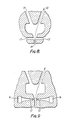
- an optical signal source 1 will be arranged to produce optical signals for the control of a fluidic device 2 which may be remotely located from the optical signal source 1 and which may comprise a fluidic switch (e.g. bistable switch) as depicted in Figure 8 or Figure 9 or a fluidic amplifier as depicted in Figure 10.
- the optical control signals produced by the source 1 may be applied to an optical-mechanical transducer 3 either through an optical fibre 4, more particularly in the case of a remotely located fluidic device 2, or through a light focussing arrangement.
- the optical to mechanical transducer 3 may, for example, comprise any of the transducers depicted in Figures 2 to 4.
- the light beam derived from the optical control signal source 1 passes through the light transmissive wall 5 of a gas-filled vessel 6 containing a small volume of fibrous material 7 which has high light absorbency for the conversion of light energy into thermal energy.
- the vessel 6 shown in spherical it may be non-spherical to increase its compliance.
- the heat generated by the fibrous material 7 rapidly heats part of the gas filling of the vessel 6 and causes the wall 5 to expand thereby generating a pressure wave in the air or liquid 8 surrounding the vessel 6.
- This air or liquid 8 may be the operating fluid for controlling the fluidic device 2 ( Figure 1). If air is the operating fluid then the vessel 6 could be dispensed with.
- the pressure wave produced by the transducer of Figure 2 may be applied to fluid in the control port C2 to cause the fluid power stream FP to be switched from the output port O2 to the output port O1.
- FIG 3 An alternative form of gas-filled optical-mechanical transducer is shown in Figure 3.
- the vessel 9 which may be rectangular as shown contains a plurality of thin light absorbing vanes 10 which receive light from the optical control signal source 1 (Figure 1) through the light transmissive wall 11 of the vessel and respond by heating the gas filling of the vessel to thereby produce a pressure wave PW which is accordingly applied to the surrounding gas or liquid 12 which may constitute the operating fluid in one of the control ports of the fluidic device 2 ( Figure 1).
- FIG. 4 Yet another embodiment is depicted in Figure 4 in which the optical control signals derived from the source 1 ( Figure 1) fall on one side of a diphragm 13.
- This diaphragm may be composed of a single material or it may comprise a plurality of layers of thermally dissimilar material having different coefficients of expansion. In either case the heat from the light signal causes the diaphragm 13 to bend in order to produce a pressure wave PX which can be applied to the operating fluid of the fluidic device 2 ( Figure 1) to produce operation of the switch or a change in amplifier output in the case of a fluidic amplifier.
- the pressure waves produced by the optical to mechanical transducers may be applied directly to the control fluid of the fluidics device 2 ( Figure 1) or it could be applied to bias control resistors associated with the fluidics device.
- the transducer may be embodied in the fluidics device itself in which case the body of the fluidics device may be light transmissive to allow the light signals to impinge on the optical mechanical transducer through the wall of the device.
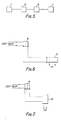
- this control arrangement includes two transducers 14 and 15.
- the transducer 14 comprises an photo-electric transducer which produces an electrical output which in turn is fed to an electro-mechanical transducer 15.
- FIGs 6 and 7 of the drawings Examples of such transducers 14 and 15 are depicted in Figures 6 and 7 of the drawings.
- a photo-voltaic detector 16 e.g. silicon or gallium arsenide or gallium aluminium arsenide diode
- the electrical output from the photo-voltaic detector 16 is applied to an electro-magnetic transducer 26 to derive the pressure impulse PB for use in operating the fluidics device either directly or through fluidics control means (e.g. bias resistors etc).
- the latter may be remotely located with the fluidics device in cases where the transmission path for the optical signal over the optical fibre 4 is a potentially explosive environment or an electrically intrusive path as previously explained.
- the fluidics device includes mechanical acoustic transducers 18 and 19 which are arranged for applying acoustic control signals to the respective control ports C1 and C2 for switching purposes. These transducers may receive their mechanical input 5 from the pressure waves generated by tranducers such as illustrated in Figures 2, 3 and 4 or Figures 6 and 7.
- the figure 10 fluidic proportional amplifier comprises a two-stage amplifier arrangement and has restrictions 20, 21, 22 and 23.
- the incoming light signal may fall upon opto-mechanical transducers 24 and 25 in order to vary the restrictions 20 and 23 so as to bring about a change in the output of the amplifier.
Landscapes
- Engineering & Computer Science (AREA)
- General Engineering & Computer Science (AREA)
- Theoretical Computer Science (AREA)
- Physics & Mathematics (AREA)
- Fluid Mechanics (AREA)
- Mechanical Engineering (AREA)
- Fluid-Pressure Circuits (AREA)
- Mechanical Light Control Or Optical Switches (AREA)
Applications Claiming Priority (2)
| Application Number | Priority Date | Filing Date | Title |
|---|---|---|---|
| GB878707528A GB8707528D0 (en) | 1987-03-30 | 1987-03-30 | Operating control arrangements for fluidic devices |
| GB8707528 | 1987-03-30 |
Publications (2)
| Publication Number | Publication Date |
|---|---|
| EP0285336A2 true EP0285336A2 (de) | 1988-10-05 |
| EP0285336A3 EP0285336A3 (de) | 1989-05-10 |
Family
ID=10614902
Family Applications (1)
| Application Number | Title | Priority Date | Filing Date |
|---|---|---|---|
| EP88302647A Withdrawn EP0285336A3 (de) | 1987-03-30 | 1988-03-25 | Steuerungsanordnungen für Strahlelemente |
Country Status (2)
| Country | Link |
|---|---|
| EP (1) | EP0285336A3 (de) |
| GB (1) | GB8707528D0 (de) |
Cited By (1)
| Publication number | Priority date | Publication date | Assignee | Title |
|---|---|---|---|---|
| EP0452056A1 (de) * | 1990-04-10 | 1991-10-16 | Imi Norgren Limited | Pneumatikzylinder |
Family Cites Families (9)
| Publication number | Priority date | Publication date | Assignee | Title |
|---|---|---|---|---|
| BE622756A (de) * | 1961-10-04 | |||
| US3228411A (en) * | 1964-01-22 | 1966-01-11 | Harald W Straub | Light transducer for fluid amplifier |
| US3534754A (en) * | 1968-02-21 | 1970-10-20 | Pitney Bowes Inc | Transducer |
| US3591809A (en) * | 1969-01-27 | 1971-07-06 | Johnson Service Co | Fluidic radiation sensor varying the viscosity of a fluid stream |
| AT318261B (de) * | 1970-10-30 | 1974-10-10 | Enfo Grundlagen Forschungs Ag | Signalwandler für fluidische Steuerungen |
| US4512371A (en) * | 1983-06-13 | 1985-04-23 | The United States Of America As Represented By The Secretary Of The Army | Photofluidic interface |
| GB2165062B (en) * | 1984-09-28 | 1988-10-05 | Gen Electric Plc | An optical sensor |
| US4610274A (en) * | 1985-06-04 | 1986-09-09 | United Technologies Corporation | Fluidic device |
| US4606375A (en) * | 1985-06-04 | 1986-08-19 | United Technologies Corporation | Fluidic device |
-
1987
- 1987-03-30 GB GB878707528A patent/GB8707528D0/en active Pending
-
1988
- 1988-03-25 EP EP88302647A patent/EP0285336A3/de not_active Withdrawn
Cited By (2)
| Publication number | Priority date | Publication date | Assignee | Title |
|---|---|---|---|---|
| EP0452056A1 (de) * | 1990-04-10 | 1991-10-16 | Imi Norgren Limited | Pneumatikzylinder |
| US5111847A (en) * | 1990-04-10 | 1992-05-12 | Norgren Martonair Limited | Pneumatic actuator |
Also Published As
| Publication number | Publication date |
|---|---|
| GB8707528D0 (en) | 1987-05-07 |
| EP0285336A3 (de) | 1989-05-10 |
Similar Documents
| Publication | Publication Date | Title |
|---|---|---|
| US3175569A (en) | Pure fluid pulse generator | |
| US3395719A (en) | Fluid-operated control system | |
| EP0285336A2 (de) | Steuerungsanordnungen für Strahlelemente | |
| US3390692A (en) | Pneumatic signal generator | |
| US5081328A (en) | Flow switch | |
| EP0813802B1 (de) | Passiver akusto-optischer modulator | |
| US4538633A (en) | Optical-hydraulic control system | |
| US3521655A (en) | Fluidic temperature sensors | |
| US3402737A (en) | Fluid pressure modulating servo valve | |
| GB9107317D0 (en) | Pneumatic actuator | |
| GB2165062A (en) | Optically controlled actuator | |
| US3311122A (en) | Electro-fluid transducer | |
| US3412745A (en) | Fluid superheterodyne detector circuit | |
| EP1266143B2 (de) | Kabelloses, eigensicheres ventil | |
| US4610274A (en) | Fluidic device | |
| US3747644A (en) | Electric to fluidic transducer | |
| Hu et al. | A fast opto-pneumatic converter | |
| US4854219A (en) | Optical control system | |
| USRE26605E (en) | Electro-sonic fluid amplifier | |
| McKenzie et al. | High sensitivity micromachined optical-to-fluid pressure converter for use in an optical actuation scheme | |
| JPS61502077A (ja) | 改良された光フアイバ遠隔センサ | |
| Hale et al. | High-sensitivity optopneumatic convertor | |
| US3636967A (en) | Control of fluidic devices | |
| JPH04164581A (ja) | マイクロ・マシン | |
| JPS6222641Y2 (de) |
Legal Events
| Date | Code | Title | Description |
|---|---|---|---|
| PUAI | Public reference made under article 153(3) epc to a published international application that has entered the european phase |
Free format text: ORIGINAL CODE: 0009012 |
|
| AK | Designated contracting states |
Kind code of ref document: A2 Designated state(s): DE FR GB IT |
|
| PUAL | Search report despatched |
Free format text: ORIGINAL CODE: 0009013 |
|
| AK | Designated contracting states |
Kind code of ref document: A3 Designated state(s): DE FR GB IT |
|
| STAA | Information on the status of an ep patent application or granted ep patent |
Free format text: STATUS: THE APPLICATION IS DEEMED TO BE WITHDRAWN |
|
| 18D | Application deemed to be withdrawn |
Effective date: 19891111 |