EP0285599A2 - Elément de fermeture - Google Patents
Elément de fermeture Download PDFInfo
- Publication number
- EP0285599A2 EP0285599A2 EP88890062A EP88890062A EP0285599A2 EP 0285599 A2 EP0285599 A2 EP 0285599A2 EP 88890062 A EP88890062 A EP 88890062A EP 88890062 A EP88890062 A EP 88890062A EP 0285599 A2 EP0285599 A2 EP 0285599A2
- Authority
- EP
- European Patent Office
- Prior art keywords
- bearing plate
- base plate
- stiffening rib
- plate
- bent
- Prior art date
- Legal status (The legal status is an assumption and is not a legal conclusion. Google has not performed a legal analysis and makes no representation as to the accuracy of the status listed.)
- Granted
Links
Images

Classifications
-
- B—PERFORMING OPERATIONS; TRANSPORTING
- B42—BOOKBINDING; ALBUMS; FILES; SPECIAL PRINTED MATTER
- B42F—SHEETS TEMPORARILY ATTACHED TOGETHER; FILING APPLIANCES; FILE CARDS; INDEXING
- B42F13/00—Filing appliances with means for engaging perforations or slots
- B42F13/16—Filing appliances with means for engaging perforations or slots with claws or rings
- B42F13/20—Filing appliances with means for engaging perforations or slots with claws or rings pivotable about an axis or axes parallel to binding edges
- B42F13/22—Filing appliances with means for engaging perforations or slots with claws or rings pivotable about an axis or axes parallel to binding edges in two sections engaging each other when closed
- B42F13/24—Filing appliances with means for engaging perforations or slots with claws or rings pivotable about an axis or axes parallel to binding edges in two sections engaging each other when closed wherein one section is in the form of fixed rods
Definitions
- the invention relates to a locking mechanism for a holding device for perforated loose sheets with fixed thorns attached to a base plate and pivotally held on the base plate and connected to each other, movable and having a curvature thorns, which can be brought into contact with the fixed thorns, wherein the movable mandrels are connected to one another by means of a bearing plate which can be pivoted in the base plate by means of tabs which are bent out of this and pass through the openings in the bearing plate with little play and which are bent around a common axis running parallel to the connecting line of the fastening points of the movable mandrels on the bearing plate is stored.
- Such a locking mechanism has been e.g. known from DE-PS 816 689.
- a smooth base plate is provided apart from a bent-out tab for receiving the mounting of an actuating lever of the locking mechanism and two small tabs for holding the bearing plate.
- the movable mandrels are held in an essentially smooth bearing plate, which is provided with two slots which are penetrated by the two small tabs of the base plate.
- the tabs passing through the bearing plate are bent above the same.
- the aim of the invention is to avoid these disadvantages and to propose a locking mechanism of the type mentioned in the introduction, in which, despite a high degree of security of the connection of the two plates against unintentional loosening, a high degree of mobility of the two plates is provided with respect to one another.
- the base plate has a stiffening rib which runs parallel to the bending axis of the flaps bent out of the base plate and the bearing plate on its end face facing the stiffening rib of the base plate has protruding projections therefrom which engage in openings with little play which are arranged in the side wall of the stiffening rib facing the end face of the bearing plate.
- This bracket can be produced by simply punching out the tabs from the base plate, which can be done in a common operation with punching out the base plate itself.
- the tabs in conjunction with the projections simultaneously ensure a corresponding determination of the position of the bearing plate both in the direction of the tilting axis of the bearing plate and perpendicularly to it, thereby also ensuring that the end faces of the movable mandrels meet those of the fixed mandrels.
- the intersecting tabs and projections and the formation of the reinforcing rib on the base plate result in a very secure fixing of the bearing plate to the base plate, the displaceability of the bearing plate in the direction transverse to the pivot axis of the bearing plate determined by the tabs bent out of the base plate due to the reinforcing rib can be kept very small. This also makes it possible to bend the tabs protruding from the base plate only slightly above the bearing plate, whereby even larger tolerances can be permitted, and still achieve a very high degree of security against unintentional loosening of the connection between the base plate and the bearing plate
- stiffening rib allows the use of thinner sheets without the strength and rigidity of the locking mechanism being impaired.
- stiffening rib also creates a corresponding stop for the bearing plate, which means that the very simple storage can be used.
- the bearing plate in its central region has a preferably trapezoidal shape lying in the plane thereof and the edges of two edges of the bearing mandrels arranged transversely to this and running essentially in the direction of the connecting line of the fastening points of the movable mandrels run in opposite directions.
- the shape of the bearing plate also ensures that it can be kept relatively narrow, and yet a sufficient lever arm is created for a spring that engages this shape and acts on the movable mandrels in the sense of opening the locking mechanism.
- the bearing plate has a stiffening rib which is essentially trapezoidal in cross section and in whose web the movable mandrels are inserted.
- the stiffening rib which enables a reduction in the material thickness of the bearing plate, also creates space for riveting the movable mandrels to the bearing plate.
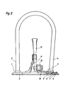
- the locking mechanism has a base plate 1, in which the fixed mandrels 2 are held. Furthermore, a bearing plate 3 is pivotally held on the base plate 1, in which the movable mandrels 4 are held.
- the base plate 1 is provided with a stiffening rib 5, which extends over most of the base plate, but the area of the bores 6 ⁇ which are used to hold fastening elements, such as e.g. Rivets are provided and leaves the area of the bearing plate 3 free.
- the bearing plate 3 is embedded between the stiffening rib 5 and a further stiffening rib 5 'running along the edge of the base plate.
- the bearing plate 3 on its end face facing the stiffening rib 5 ⁇ has projections 6 which pass through openings 7 arranged on the end wall facing the bearing plate 3 of the stiffening rib 5 ⁇ and engage under the web of the stiffening rib 5 ⁇ .
- the dimensions of the projections on the one hand and the openings 7 on the other hand are dimensioned such that there is only a slight play between these parts.
- tab 8 are punched out of the base plate and bent upwards. These tabs 8 penetrate openings 9 of the bearing plate 3, the protrusion of the tabs 8 being bent after the bearing plate 3 has been placed in the direction of the stiffening rib 5 ⁇ , thereby a later lifting of the bearing plate 3 is prevented and proper storage of the bearing plate 3 is ensured.
- the bearing plate 3 likewise has a stiffening rib 10 on the web area of which the movable mandrels 4 pass. In addition to stiffening the bearing plate 3, this measure also creates space for the formation of the rivet heads of the mandrels 4 on the underside of the bearing plate 3. The same also applies to the fixed mandrels 2, which are likewise held in the base plate in the area of the stiffening rib 5 and are connected to the base plate by means of a rivet.
- a retaining tab 11 is punched out and bent open, which serves to accommodate the mounting of the locking lever 12, which rests with its roller 13 on the raised stiffening rib 10 of the mounting plate 3 and this in the closed position of the locking mechanism against the force of the held in the base plate 1 and on the underside of the bearing plate 3 spring 14 keeps closed.
- the edges of the bearing plate 3 run in opposite directions on both sides of the bearing axis determined by the openings 9.
- the recesses 16 on one edge correspond exactly to the projections 6 on the other edge.
- the lengths of the two edges of the bearing plate 3 running parallel to the one edge of the base plate in the region of their shape 15 are the same length, as are the lengths of the individual sections of the edges of the bearing plate 3 running on both sides of the stiffening rib 10, so that they are the same length the bearing plates 3 can be lined up one after the other in their plane without there being any vacancies. This enables particularly good utilization of the raw material used.
Landscapes
- Connection Of Plates (AREA)
- Pivots And Pivotal Connections (AREA)
Applications Claiming Priority (2)
| Application Number | Priority Date | Filing Date | Title |
|---|---|---|---|
| AT825/87 | 1987-04-03 | ||
| AT82587A AT391657B (de) | 1987-04-03 | 1987-04-03 | Verschlusselement |
Publications (3)
| Publication Number | Publication Date |
|---|---|
| EP0285599A2 true EP0285599A2 (fr) | 1988-10-05 |
| EP0285599A3 EP0285599A3 (en) | 1989-04-12 |
| EP0285599B1 EP0285599B1 (fr) | 1991-06-26 |
Family
ID=3500617
Family Applications (1)
| Application Number | Title | Priority Date | Filing Date |
|---|---|---|---|
| EP19880890062 Expired - Lifetime EP0285599B1 (fr) | 1987-04-03 | 1988-03-17 | Elément de fermeture |
Country Status (3)
| Country | Link |
|---|---|
| EP (1) | EP0285599B1 (fr) |
| AT (1) | AT391657B (fr) |
| DE (1) | DE3863380D1 (fr) |
Cited By (2)
| Publication number | Priority date | Publication date | Assignee | Title |
|---|---|---|---|---|
| EP0314664A3 (en) * | 1987-09-08 | 1990-01-10 | Koloman Handler Gesellschaft M.B.H. | Bottom plate for a ring binder |
| WO2004018225A1 (fr) * | 2002-08-23 | 2004-03-04 | Schneider Guenter Karl | Mecanisme de classeur |
Families Citing this family (2)
| Publication number | Priority date | Publication date | Assignee | Title |
|---|---|---|---|---|
| DE19619822C2 (de) * | 1996-05-16 | 1998-04-23 | Elba Buerosysteme Erich Kraut | Aufreihvorrichtung für gelochtes Papiergut o. dgl. und Verfahren zu ihrer Herstellung |
| AT518672B1 (de) * | 2016-05-17 | 2017-12-15 | Karl Schneider Günter | Ordnermechanik |
Family Cites Families (4)
| Publication number | Priority date | Publication date | Assignee | Title |
|---|---|---|---|---|
| DE816689C (de) * | 1950-06-11 | 1951-10-11 | Ludwig Breitrueck | Aufreihvorrichtung fuer Briefordner |
| DE2810955A1 (de) * | 1978-03-14 | 1979-09-27 | Georg Fendt | Ordner mit locher |
| DE2919907A1 (de) * | 1979-05-17 | 1980-11-20 | Otto Schmidt | Ordner mit innerer aufreihmechanik |
| FI82216C (fi) * | 1985-06-03 | 1991-02-11 | H J Horn | Tillslutningsmekanism foer paermar. |
-
1987
- 1987-04-03 AT AT82587A patent/AT391657B/de not_active IP Right Cessation
-
1988
- 1988-03-17 DE DE8888890062T patent/DE3863380D1/de not_active Expired - Fee Related
- 1988-03-17 EP EP19880890062 patent/EP0285599B1/fr not_active Expired - Lifetime
Cited By (4)
| Publication number | Priority date | Publication date | Assignee | Title |
|---|---|---|---|---|
| EP0314664A3 (en) * | 1987-09-08 | 1990-01-10 | Koloman Handler Gesellschaft M.B.H. | Bottom plate for a ring binder |
| WO2004018225A1 (fr) * | 2002-08-23 | 2004-03-04 | Schneider Guenter Karl | Mecanisme de classeur |
| US7318684B2 (en) | 2002-08-23 | 2008-01-15 | Schneider Guenter Karl | File mechanism |
| CN100430242C (zh) * | 2002-08-23 | 2008-11-05 | 冈特·卡尔·施奈德 | 文件夹机构 |
Also Published As
| Publication number | Publication date |
|---|---|
| EP0285599A3 (en) | 1989-04-12 |
| EP0285599B1 (fr) | 1991-06-26 |
| ATA82587A (de) | 1990-05-15 |
| AT391657B (de) | 1990-11-12 |
| DE3863380D1 (de) | 1991-08-01 |
Similar Documents
| Publication | Publication Date | Title |
|---|---|---|
| EP1383967B1 (fr) | Couvercle pour un systeme d'ecoulement des eaux | |
| DE2729151C2 (de) | Sicherheitsgurtverschluß | |
| DE2940463C2 (de) | Längsverschiebbarer Kraftfahrzeugsitz | |
| DE2815638C2 (de) | Reißverschlußschieber | |
| DE3447817A1 (de) | Hoehenverstelleinrichtung fuer den umlenkbeschlag eines sicherheitsgurtes | |
| DE4032427A1 (de) | Verbindungsvorrichtung fuer ein wischblatt, insbesondere an einem kraftfahrzeug | |
| DE2364669C2 (de) | Zusammenlegbare Kiste oder Behälter | |
| DE1943621A1 (de) | Verformbare,stapelbare Verschlussklammer fuer Verschnuerungen,Umreifungen od.dgl. | |
| DE2540118C3 (de) | Tragschiene für eine Unterdecke | |
| EP0285599B1 (fr) | Elément de fermeture | |
| EP0314664B1 (fr) | Plaque de base pour classeur à anneaux | |
| EP1468148A1 (fr) | Dispositif de verrouillage de grille de recouvrement | |
| DE2718402C3 (de) | Haltegriff für Fahrzeuge | |
| AT392236B (de) | Verschlussmechanik | |
| DE3230312A1 (de) | Locher fuer papier- und pappwaren aus im wesentlichen zweistrangpress- bzw. extrusionsprofilen | |
| DE3049921C2 (fr) | ||
| DE19545785C2 (de) | Verriegelung für ein Kassetten-Deckenelement | |
| EP0911180B1 (fr) | Mécanisme d'enfilage | |
| CH634631A5 (de) | Verriegelungsvorrichtung fuer eine raffbare lamellenjalousie. | |
| DE29905779U1 (de) | Raster-Verschluß | |
| DE2408786C2 (de) | Schienenartiges Luftauslaßelement für Raumbelüftungsanlagen | |
| DE7713094U1 (de) | Griff, insbesondere haltegriff fuer fahrzeuge | |
| DE3326479C2 (de) | Brieflocher | |
| EP0389438B1 (fr) | Pare-neige | |
| DE3116331C2 (de) | Aufhängevorrichtung für Vorhänge oder dgl. |
Legal Events
| Date | Code | Title | Description |
|---|---|---|---|
| PUAI | Public reference made under article 153(3) epc to a published international application that has entered the european phase |
Free format text: ORIGINAL CODE: 0009012 |
|
| AK | Designated contracting states |
Kind code of ref document: A2 Designated state(s): DE ES FR GB IT NL |
|
| PUAL | Search report despatched |
Free format text: ORIGINAL CODE: 0009013 |
|
| AK | Designated contracting states |
Kind code of ref document: A3 Designated state(s): DE ES FR GB IT NL |
|
| 17P | Request for examination filed |
Effective date: 19890429 |
|
| 17Q | First examination report despatched |
Effective date: 19901128 |
|
| GRAA | (expected) grant |
Free format text: ORIGINAL CODE: 0009210 |
|
| AK | Designated contracting states |
Kind code of ref document: B1 Designated state(s): DE ES FR GB IT NL |
|
| PG25 | Lapsed in a contracting state [announced via postgrant information from national office to epo] |
Ref country code: ES Free format text: THE PATENT HAS BEEN ANNULLED BY A DECISION OF A NATIONAL AUTHORITY Effective date: 19910626 |
|
| REF | Corresponds to: |
Ref document number: 3863380 Country of ref document: DE Date of ref document: 19910801 |
|
| GBT | Gb: translation of ep patent filed (gb section 77(6)(a)/1977) | ||
| ITF | It: translation for a ep patent filed | ||
| EN | Fr: translation not filed | ||
| PG25 | Lapsed in a contracting state [announced via postgrant information from national office to epo] |
Ref country code: FR Effective date: 19911115 |
|
| PLBE | No opposition filed within time limit |
Free format text: ORIGINAL CODE: 0009261 |
|
| STAA | Information on the status of an ep patent application or granted ep patent |
Free format text: STATUS: NO OPPOSITION FILED WITHIN TIME LIMIT |
|
| 26N | No opposition filed | ||
| REG | Reference to a national code |
Ref country code: FR Ref legal event code: ST |
|
| PGFP | Annual fee paid to national office [announced via postgrant information from national office to epo] |
Ref country code: GB Payment date: 19960314 Year of fee payment: 9 |
|
| PGFP | Annual fee paid to national office [announced via postgrant information from national office to epo] |
Ref country code: NL Payment date: 19960331 Year of fee payment: 9 |
|
| PG25 | Lapsed in a contracting state [announced via postgrant information from national office to epo] |
Ref country code: GB Effective date: 19970317 |
|
| PG25 | Lapsed in a contracting state [announced via postgrant information from national office to epo] |
Ref country code: NL Effective date: 19971001 |
|
| GBPC | Gb: european patent ceased through non-payment of renewal fee |
Effective date: 19970317 |
|
| NLV4 | Nl: lapsed or anulled due to non-payment of the annual fee |
Effective date: 19971001 |
|
| PGFP | Annual fee paid to national office [announced via postgrant information from national office to epo] |
Ref country code: DE Payment date: 20040430 Year of fee payment: 17 |
|
| PG25 | Lapsed in a contracting state [announced via postgrant information from national office to epo] |
Ref country code: IT Free format text: LAPSE BECAUSE OF NON-PAYMENT OF DUE FEES;WARNING: LAPSES OF ITALIAN PATENTS WITH EFFECTIVE DATE BEFORE 2007 MAY HAVE OCCURRED AT ANY TIME BEFORE 2007. THE CORRECT EFFECTIVE DATE MAY BE DIFFERENT FROM THE ONE RECORDED. Effective date: 20050317 |
|
| PG25 | Lapsed in a contracting state [announced via postgrant information from national office to epo] |
Ref country code: DE Free format text: LAPSE BECAUSE OF NON-PAYMENT OF DUE FEES Effective date: 20051001 |