EP0285659A1 - Cylindre et cylindres combines - Google Patents
Cylindre et cylindres combines Download PDFInfo
- Publication number
- EP0285659A1 EP0285659A1 EP87902149A EP87902149A EP0285659A1 EP 0285659 A1 EP0285659 A1 EP 0285659A1 EP 87902149 A EP87902149 A EP 87902149A EP 87902149 A EP87902149 A EP 87902149A EP 0285659 A1 EP0285659 A1 EP 0285659A1
- Authority
- EP
- European Patent Office
- Prior art keywords
- roll
- shaft
- combination
- inserting portion
- shaft inserting
- Prior art date
- Legal status (The legal status is an assumption and is not a legal conclusion. Google has not performed a legal analysis and makes no representation as to the accuracy of the status listed.)
- Granted
Links
- 239000011256 inorganic filler Substances 0.000 claims description 7
- 229910003475 inorganic filler Inorganic materials 0.000 claims description 7
- 239000000945 filler Substances 0.000 claims description 6
- 230000000295 complement effect Effects 0.000 claims description 2
- 229920005989 resin Polymers 0.000 claims description 2
- 239000011347 resin Substances 0.000 claims description 2
- 230000004323 axial length Effects 0.000 claims 1
- 238000003780 insertion Methods 0.000 abstract description 2
- 230000037431 insertion Effects 0.000 abstract description 2
- 229920003023 plastic Polymers 0.000 abstract 1
- 239000004033 plastic Substances 0.000 abstract 1
- 229920003002 synthetic resin Polymers 0.000 description 10
- 239000000057 synthetic resin Substances 0.000 description 10
- 230000002093 peripheral effect Effects 0.000 description 8
- 239000000463 material Substances 0.000 description 6
- XEEYBQQBJWHFJM-UHFFFAOYSA-N Iron Chemical compound [Fe] XEEYBQQBJWHFJM-UHFFFAOYSA-N 0.000 description 2
- 238000004519 manufacturing process Methods 0.000 description 2
- 239000007769 metal material Substances 0.000 description 2
- 238000004804 winding Methods 0.000 description 2
- 238000005299 abrasion Methods 0.000 description 1
- 229910052782 aluminium Inorganic materials 0.000 description 1
- XAGFODPZIPBFFR-UHFFFAOYSA-N aluminium Chemical compound [Al] XAGFODPZIPBFFR-UHFFFAOYSA-N 0.000 description 1
- 239000000919 ceramic Substances 0.000 description 1
- 239000002131 composite material Substances 0.000 description 1
- 238000013329 compounding Methods 0.000 description 1
- 229920001971 elastomer Polymers 0.000 description 1
- 230000005611 electricity Effects 0.000 description 1
- 239000004744 fabric Substances 0.000 description 1
- 229910052742 iron Inorganic materials 0.000 description 1
- 229910052751 metal Inorganic materials 0.000 description 1
- 239000002184 metal Substances 0.000 description 1
- 238000012986 modification Methods 0.000 description 1
- 230000004048 modification Effects 0.000 description 1
- 239000000123 paper Substances 0.000 description 1
- 239000005060 rubber Substances 0.000 description 1
- 238000005488 sandblasting Methods 0.000 description 1
- 238000007493 shaping process Methods 0.000 description 1
- 229910001220 stainless steel Inorganic materials 0.000 description 1
- 239000010935 stainless steel Substances 0.000 description 1
- 230000003068 static effect Effects 0.000 description 1
- 229920003051 synthetic elastomer Polymers 0.000 description 1
- 229920002994 synthetic fiber Polymers 0.000 description 1
- 239000005061 synthetic rubber Substances 0.000 description 1
- 239000002023 wood Substances 0.000 description 1
- 230000037303 wrinkles Effects 0.000 description 1
Images



Classifications
-
- F—MECHANICAL ENGINEERING; LIGHTING; HEATING; WEAPONS; BLASTING
- F16—ENGINEERING ELEMENTS AND UNITS; GENERAL MEASURES FOR PRODUCING AND MAINTAINING EFFECTIVE FUNCTIONING OF MACHINES OR INSTALLATIONS; THERMAL INSULATION IN GENERAL
- F16C—SHAFTS; FLEXIBLE SHAFTS; ELEMENTS OR CRANKSHAFT MECHANISMS; ROTARY BODIES OTHER THAN GEARING ELEMENTS; BEARINGS
- F16C13/00—Rolls, drums, discs, or the like; Bearings or mountings therefor
-
- B—PERFORMING OPERATIONS; TRANSPORTING
- B21—MECHANICAL METAL-WORKING WITHOUT ESSENTIALLY REMOVING MATERIAL; PUNCHING METAL
- B21B—ROLLING OF METAL
- B21B31/00—Rolling stand structures; Mounting, adjusting, or interchanging rolls, roll mountings, or stand frames
-
- B—PERFORMING OPERATIONS; TRANSPORTING
- B65—CONVEYING; PACKING; STORING; HANDLING THIN OR FILAMENTARY MATERIAL
- B65H—HANDLING THIN OR FILAMENTARY MATERIAL, e.g. SHEETS, WEBS, CABLES
- B65H27/00—Special constructions, e.g. surface features, of feed or guide rollers for webs
-
- B—PERFORMING OPERATIONS; TRANSPORTING
- B65—CONVEYING; PACKING; STORING; HANDLING THIN OR FILAMENTARY MATERIAL
- B65H—HANDLING THIN OR FILAMENTARY MATERIAL, e.g. SHEETS, WEBS, CABLES
- B65H2404/00—Parts for transporting or guiding the handled material
- B65H2404/10—Rollers
- B65H2404/11—Details of cross-section or profile
- B65H2404/111—Details of cross-section or profile shape
- B65H2404/1112—D-shape
-
- B—PERFORMING OPERATIONS; TRANSPORTING
- B65—CONVEYING; PACKING; STORING; HANDLING THIN OR FILAMENTARY MATERIAL
- B65H—HANDLING THIN OR FILAMENTARY MATERIAL, e.g. SHEETS, WEBS, CABLES
- B65H2404/00—Parts for transporting or guiding the handled material
- B65H2404/10—Rollers
- B65H2404/11—Details of cross-section or profile
- B65H2404/111—Details of cross-section or profile shape
- B65H2404/1116—Polygonal cross-section
-
- B—PERFORMING OPERATIONS; TRANSPORTING
- B65—CONVEYING; PACKING; STORING; HANDLING THIN OR FILAMENTARY MATERIAL
- B65H—HANDLING THIN OR FILAMENTARY MATERIAL, e.g. SHEETS, WEBS, CABLES
- B65H2404/00—Parts for transporting or guiding the handled material
- B65H2404/10—Rollers
- B65H2404/13—Details of longitudinal profile
- B65H2404/132—Details of longitudinal profile arrangement of segments along axis
- B65H2404/1321—Segments juxtaposed along axis
- B65H2404/13211—Segments juxtaposed along axis and interconnected by gearing, e.g. differential gearing
-
- B—PERFORMING OPERATIONS; TRANSPORTING
- B65—CONVEYING; PACKING; STORING; HANDLING THIN OR FILAMENTARY MATERIAL
- B65H—HANDLING THIN OR FILAMENTARY MATERIAL, e.g. SHEETS, WEBS, CABLES
- B65H2404/00—Parts for transporting or guiding the handled material
- B65H2404/10—Rollers
- B65H2404/13—Details of longitudinal profile
- B65H2404/134—Axle
- B65H2404/1342—Built-up, i.e. arrangement for mounting axle element on roller body
Definitions
- This invention generally relates to a combination roll, and more particularly, to a roll unit for constituting the combination roll and the combination roll or roll assembly formed of a plurality of roll units.
- roll used here broadly means a member having a roll shaft and an outer peripheral contact or operative portion, which is integral, in operation, with the roll shaft so as to rotate conjointly with the roll shaft.
- roll herein used includes rolls employable in various machines for manufacturing, processing or using a sheet or film material such as a synthetic resin sheet or film, paper, etc. or various feed rolls or wind-up rolls usable in business machines, or print rolls.
- such rolls include a roll of a continuous length formed integrally and a combination roll which is formed of a plurality of roll portions in sections or short lengths, which are to be combined to form a roll assembly.
- These two kinds of rolls are chosen according to the uses or necessity.
- the roll of a continuous length has such disadvantages that it can not cope with a change in width of the product, it is difficult to be manufactured and heavy in weight, .it has a large contact area, which produces a large frictional resistance and accordingly causes, for example, wrinkle or static electricity on the product. Therefore, for the use in which these disadvantages do matter, a combination roll formed of a plurality of roll portions of short lengths, which is free from th se problems is chosen.
- the roll portions of a short length constituting the conventional combination roll comprises a contact portion and a shaft inserting portion which are made of a synthetic resin or rubber and an insert member of a metallic material which is fitted in the shaft inserting portion.
- These roll portions must be mounted on and fixed to the roll shaft by setting screws into threaded holes formed on the metallic insert member for each of the roll portions.
- each of the roll portions constituting the combination roll is made of a synthetic material and a metallic material
- the shaping of the roll portions and the insertion of the metallic insert member should be carried out at separate steps. This necessitates extra steps and costs for the manufacturing of the rolls.
- the present invention has been made to obviate the above-mentioned problems, and it is an object of the present invention to provide a roll unit and a roll assembly, which are capable of simplifying the step of fixing plural roll portions to a roll shaft and capable of facilitating the adjustment of the entire roll width of the combination roll, and capable of easily forming the roll portions only from, for example, a synthetic resin, reducing the weight of the roll portions.
- a roll unit for a combination roll including a shaft inserting portion having a hole formed, at a central portion thereof, for passing a roll shaft therethrough and a roll portion formed integrally with said shaft inserting portion and having, at an outer circumferential periphery thereof, a roll contact portion or operative portion, which roll unit for a combination roll comprises engaging means provided, at opposite ends of the shaft inserting portion, for respectively engaging with corresponding ends of a shaft inserting portion of a roll unit which is to be combined.
- a combination roll including a roll shaft and a plurality of roll units mounted on the roll shaft, in which said roll units each comprise a roll portion formed with a contact portion and a shaft inserting portion concentric with said roll portion, said shaft inserting portion having, at its opposite ends, engaging means engageable with corresponding shaft inserting portion of each of adjacent roll units, and which combination roll further comprises a locking means for locking said shaft inserting portion to the roll shaft inserted through said shaft inserting portion so as.to rotate the shaft inserting portion conjointly with the roll shaft.
- F ig.l is a perspective view of elements constituting a combination roll according to a first embodiment of the present invention
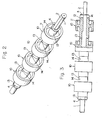
- Fig.2 is a perspective view of the combination roll in full scale, showing it in the assembled state
- Fig.3 shows a partly centrally sectioned view of the roll of Fig.2.
- 1 is a roll shaft having a circular configuration in section and formed, in continuous length, from aluminum, stainless steel, iron, ceramics or synthetic resins.
- the roll shaft 1 has an end 'portion 2 whose outer periphery is partly cut so as to form a D-shape in section.
- the roll shaft 1 further has grooves 3, 3 at opposite end portions thereof for receiving E-rings therein, respectively.
- the spacing between these grooves 3, 3 is a length determined by the length of the number of roll units 10 combined as will be described in detail later and it has a length corresponding to the total length of four roll units 10 in the embodiment as illustrated.
- the roll unit 10 has, at a central portion thereof, a cylindrical contact portion or an operative portion 11 which is operative, for example, for feeding or winding up the product, and a shaft inserting portion 12 having a cylindrical through-hole concentric with the contact portion 11, at opposite ends in the axial direction of the unit, around the center thereof.
- One end of the shaft inserting portion 12 has, on the peripheral.end edge thereof, two engaging projections 13 at angular intervals of 180°, while the other end of the shaft inserting portion 12 has two engaging recesses 14 engageable with the engaging projections 13, respectively, at angular intervals of 180°.
- a plurality of roll units 10 are thus prepared and they are mounted around the roll shaft with the engaging projections 13 engaged with the corresponding engaging recesses 14, respectively, and with the assembly of the roll units pressed by the E-rings 4, 4 inwardly, to form a combined roll or a roll assembly having a desired width.
- the through-hole of the shaft inserting portion 12 of the roll unit 10a which is located at the end of the roll shaft 1 where the D-cut portion 2 is formed, has a sectional configuration of D-shape complementary with the D-shape of the D-cut portion 2.
- the roll units 10 mounted on the roll shaft 1 are locked with respect to the roll shaft 1 through the roll unit 10a located at the shaft end.
- Such a D-cut portion 2 is effective to easily and surely fix the roll units 10 to the roll shaft 1 and to surely transmit the driving force between the roll shaft 1 and the entire roll unit 10.
- the D-cut portion 2 formed on the roll shaft 1 is formed at one end portion of the roll shaft 1 in the above-mentioned embodiment, but it may be formed at either end portion of the roll shaft 1 as illustrated in Fig.4. In this case, the length of the D-cut portion 2 in the longitudinal direction thereof may be selected as desired. Alternatively, the D-cut portion may be formed all along the length of the roll shaft 1 as illustrated in Fig.5. In especial, when the D-cut portion 2 is formed along the entire length of the roll shaft 1, all the roll units may be units 101,.102 having the same through-hole 12a having a D-shaped configuration in section and they may be placed at any given position in an assembly when they are assembled. This enables the number of the kinds of the parts to be reduced and simplified and the adjusting operation to be facilitated.
- each of the roll units 10 has a contact portion or operative portion 11 at a central portion thereof and a cylindrical shaft inserting portion 12 concentric with the contact portion 11 which is projected outwardly in the axial direction from the opposite ends of the axial direction of the unit, around the central axis thereof.
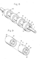
- a combination roll of the present invention may be formed, for example, as illustrated in Figs.9 to 11.
- the essential configuration of the present embodiment may be substantially the same as that of the first embodiment. This embodiment, however, is different from the first embodiment, in that the lengths in the axial direction of the shaft inserting portion 12 and the contact portion 11 are selected so that the contact portions 11 of the respective roll units 10 form a continuous, flush surface when the engaging portions 13 and 14 of the shaft inserting portions are engaged with each other.
- the engaging portions 13 and 14 may be formed by a recess which is concaved inwardly in the axial direction from a reference, axial end face of the contact portion 11 and by a projection convexed outwardly in the axial direction from such a reference face as shown in section in Fig.10.
- the reference face should not always be the end face of the contact portion 11 so long as there is a relation in lengths in the axial direction that the engaging portions 13, 14 of the shaft inserting portions 12 may be engageable with each other, while establishing the state in which the corresponding end faces of the contact portions are butt- combined with each other.
- the width of the roll operative surface may be freely selected according to necessity by changing the number of the roll units 10 to be combined. Furthermore, only a portion of the roll operative surface, which is subjected to considerable abrasion, may be replaced so that the surface conditions of the entire width of the roll can be kept desirable without replacing the complete roll assembly. Moreover, the material of the roll unit may be selected according to the position where the unit is situated so that".the wearing of the roll may be uniform as a whole.
- the configuration of the contact portion 11 is not limited to it, but it may, for example, be polygonal in section as illustrated in Fig.12.
- the polygon selected as an outer peripheral configuration of the contact portion of the roll unit may, for example, be a triangle, a square, a hexagon, an octagon, decagon, etc.
- the outer peripheral configuration of the contact portion 11 may further alternatively be of a cocoon, oval, or of a star.
- the outer peripheral configuration of the contact portion 11 may further be bilaterally asymmetrical in section, for example, the configuration may be s.uch that a lateral half is semicircular and the other half is polygonal.
- the contact portion 11 of the roll unit 10 may have an outer periphery swollen or bulging at a portion central in the axial direction of the roll unit, if it is preferred according to the use.
- various anti-slip processing such as knurling, sand-blasting, may be applied to the surface of the contact portion 11.
- the surface of the contact portion 11 may be covered with a rubber sheet or felt.
- the material of the roll units 10 may be selected suitably from metal, wood, synthetic resin, according to the use.
- the materials of the roll units 10 there can be mentioned, for example, composites comprising a synthetic resin or resins and an inorganic filler or fillers and/or a metallic filler or fillers.
- the compounding ratio of the synthetic resin or resins to the inorganic filler or fillers and/or metallic filler or fillers is, in general, 97 to 30wt% : 3 to 70wt%.
Landscapes
- Engineering & Computer Science (AREA)
- General Engineering & Computer Science (AREA)
- Mechanical Engineering (AREA)
- Rolls And Other Rotary Bodies (AREA)
- Registering, Tensioning, Guiding Webs, And Rollers Therefor (AREA)
- Rollers For Roller Conveyors For Transfer (AREA)
- Delivering By Means Of Belts And Rollers (AREA)
Abstract
Applications Claiming Priority (4)
| Application Number | Priority Date | Filing Date | Title |
|---|---|---|---|
| JP1986138406U JPS6342659U (fr) | 1986-09-09 | 1986-09-09 | |
| JP138406/86U | 1986-09-09 | ||
| JP138407/86U | 1986-09-09 | ||
| JP1986138407U JPH048139Y2 (fr) | 1986-09-09 | 1986-09-09 |
Publications (3)
| Publication Number | Publication Date |
|---|---|
| EP0285659A1 true EP0285659A1 (fr) | 1988-10-12 |
| EP0285659A4 EP0285659A4 (fr) | 1989-01-24 |
| EP0285659B1 EP0285659B1 (fr) | 1992-07-22 |
Family
ID=26471438
Family Applications (1)
| Application Number | Title | Priority Date | Filing Date |
|---|---|---|---|
| EP87902149A Expired - Lifetime EP0285659B1 (fr) | 1986-09-09 | 1987-03-26 | Cylindre et cylindres combines |
Country Status (6)
| Country | Link |
|---|---|
| US (1) | US4872247A (fr) |
| EP (1) | EP0285659B1 (fr) |
| KR (1) | KR910009834B1 (fr) |
| CA (1) | CA1287362C (fr) |
| DE (1) | DE3780625T2 (fr) |
| WO (1) | WO1988001977A1 (fr) |
Cited By (3)
| Publication number | Priority date | Publication date | Assignee | Title |
|---|---|---|---|---|
| EP0811570A3 (fr) * | 1996-06-08 | 1998-03-04 | Horizon International Inc. | Dispositif d'alimentation de papier et son rotor |
| EP1103502A3 (fr) * | 1999-10-25 | 2002-05-15 | Canon Kabushiki Kaisha | Appareil de transport de feuilles et appareil de formation d'image comprenant cet appareil de transport |
| CN104803215A (zh) * | 2014-01-27 | 2015-07-29 | 柯尼卡美能达株式会社 | 辊部件、片材输送装置以及图像形成装置 |
Families Citing this family (29)
| Publication number | Priority date | Publication date | Assignee | Title |
|---|---|---|---|---|
| US5269039A (en) * | 1992-05-08 | 1993-12-14 | Corcoran Manufacturing Company, Inc. | Sectional paint roller assembly |
| EP0580291A1 (fr) * | 1992-07-20 | 1994-01-26 | T. Sendzimir, Inc. | Réglage de profil pour laminoirs à cylindres multiples |
| US5471859A (en) * | 1992-07-20 | 1995-12-05 | T. Sendzimir, Inc. | Cluster mill crown adjustment system |
| JP2971384B2 (ja) * | 1995-12-28 | 1999-11-02 | 伊東電機株式会社 | 搬送装置 |
| US6013440A (en) | 1996-03-11 | 2000-01-11 | Affymetrix, Inc. | Nucleic acid affinity columns |
| CH692572A8 (de) * | 1996-07-10 | 2002-10-15 | Sarnatech Bnl Ltd | WELLE, AUCH ACHSE ODER ROLLKöRPER GENANNT. |
| FI102778B (sv) * | 1997-07-07 | 1999-02-15 | Suomen Intech Oy | Breddsträckvals |
| ITMI981618A1 (it) * | 1998-07-14 | 2000-01-14 | Marzoli & C Spa | Dispositivo e procedimento equalizzatore della alimentazione delle fibre in materassino ad una carda |
| US6142923A (en) * | 1998-08-05 | 2000-11-07 | Gbr Systems Corporation | Roller ring |
| JP2005520774A (ja) | 2002-03-22 | 2005-07-14 | コーニング インコーポレイテッド | 板ガラスの製造に用いられる牽引ロール |
| US6892977B2 (en) * | 2002-07-08 | 2005-05-17 | Day Nite Neon Signs Ltd. | Method and apparatus for dispensing roll stock material |
| DE10243454C5 (de) * | 2002-09-19 | 2009-10-08 | Koenig & Bauer Aktiengesellschaft | Antriebsvorrichtung einer Bearbeitungsmaschine |
| AU2003300045A1 (en) * | 2002-12-31 | 2004-07-29 | Shuttleworth, Inc. | Compression passing roller |
| DE10341229B4 (de) * | 2003-09-04 | 2007-09-06 | Koenig & Bauer Aktiengesellschaft | Leitwalze |
| US20050091821A1 (en) * | 2003-11-03 | 2005-05-05 | Best Scott D. | Method of manufacturing an article having a radio frequency identification (RFID) device |
| US7151905B2 (en) * | 2004-09-09 | 2006-12-19 | Xerox Corporation | Roller for supporting an imaging belt in a printing apparatus |
| US7198591B2 (en) * | 2005-03-18 | 2007-04-03 | Usa Sports, Inc. | Weight plate for interlocking and weight adjustment |
| DE102005048472A1 (de) * | 2005-10-07 | 2007-04-12 | Bosch Rexroth Ag | Rotationsdruckmaschine und Verfahren des Betriebs einer Rotationsdruckmaschine |
| US20080036297A1 (en) * | 2006-08-10 | 2008-02-14 | Gilbertson James R | Imaging apparatus with transport system employing snap-on idler wheel |
| US20080083078A1 (en) * | 2006-09-27 | 2008-04-10 | Fellinger Thomas J | Variable-length roller assembly for a rotary scrubber |
| US20100252393A1 (en) * | 2009-04-06 | 2010-10-07 | Chen Po-Feng | Skate-Wheel Positioning Structure |
| US8409063B2 (en) * | 2009-08-11 | 2013-04-02 | Goss International Americas, Inc. | Nip rollers with removable disks |
| JP5672540B2 (ja) * | 2011-01-11 | 2015-02-18 | 株式会社リコー | 定着装置及び画像形成装置並びに定着装置の使用方法 |
| US20150020494A1 (en) * | 2013-07-19 | 2015-01-22 | Ornek Makina Sanayi Ve Ticaret Limited Sirketi | Fiber unbundling assembly |
| CN105565048A (zh) * | 2014-10-13 | 2016-05-11 | 无锡市恒盛电机有限公司 | 薄膜导辊结构 |
| TWI566952B (zh) * | 2015-10-06 | 2017-01-21 | 虹光精密工業股份有限公司 | 傳輸輪以及包含其之傳動組件及事務機 |
| KR102503262B1 (ko) * | 2016-05-19 | 2023-02-22 | 에이치디씨폴리올 주식회사 | 내화학성이 우수한 폴리아릴렌 설파이드 수지 조성물 |
| US10406560B1 (en) * | 2018-10-01 | 2019-09-10 | Cp Manufacturing, Inc. | Disc for use in disc screen |
| JP7688942B2 (ja) * | 2021-03-08 | 2025-06-05 | 伊東電機株式会社 | 搬送ローラ、コンベヤ装置及び傾斜コンベヤ装置 |
Family Cites Families (18)
| Publication number | Priority date | Publication date | Assignee | Title |
|---|---|---|---|---|
| US769680A (en) * | 1902-10-14 | 1904-09-06 | Louis Bredannaz | Feed-roller for rag-pickers. |
| US776796A (en) * | 1903-12-23 | 1904-12-06 | John Lewis Perkins | Calendering-roll. |
| JPS362743Y1 (fr) * | 1958-08-15 | 1961-02-13 | ||
| JPS401184Y1 (fr) * | 1962-11-24 | 1965-01-14 | ||
| IT1034997B (it) * | 1974-04-27 | 1979-10-10 | Kloeckner Werke Ag | Rullo di guida suddiviso in sezioni supportato in una pluralita di punti per impianti di colaggio continuo |
| US3964658A (en) * | 1974-09-04 | 1976-06-22 | Edwards Edwin L | Roller replacing |
| JPS5132046A (ja) * | 1974-09-12 | 1976-03-18 | Mitsubishi Kakoki Kk | Sankiki |
| JPS618034Y2 (fr) * | 1978-01-27 | 1986-03-12 | ||
| JPS55132046U (fr) * | 1979-03-10 | 1980-09-18 | ||
| EP0058781B1 (fr) * | 1981-02-20 | 1985-06-05 | Maschinenfabrik Rieter Ag | Cylindre extracteur pour des balles de matières fibreuses |
| JPS5830640U (ja) * | 1981-08-20 | 1983-02-28 | キヤノン株式会社 | 搬送ロ−ラ− |
| JPS58109353A (ja) * | 1981-12-21 | 1983-06-29 | Hokushin Ind Inc | 紙送り用ロ−ラの製作方法 |
| JPS58109363A (ja) * | 1981-12-23 | 1983-06-29 | Fuji Xerox Co Ltd | ソ−タ |
| JPS5978064A (ja) * | 1982-10-28 | 1984-05-04 | Hitachi Ltd | 紙排出ロ−ラ |
| US4542566A (en) * | 1982-11-15 | 1985-09-24 | Corrugating Roll Corporation | Corrugating roller |
| JPS60258049A (ja) * | 1984-05-31 | 1985-12-19 | Orient Watch Co Ltd | ウエブの給送装置 |
| JPS618034A (ja) * | 1984-06-25 | 1986-01-14 | 富士通株式会社 | 超音波ドプラ血流計音声出力回路 |
| JPS6141118U (ja) * | 1984-08-15 | 1986-03-15 | 川崎製鉄株式会社 | 搬送ロ−ル |
-
1987
- 1987-03-26 DE DE8787902149T patent/DE3780625T2/de not_active Expired - Fee Related
- 1987-03-26 US US07/209,480 patent/US4872247A/en not_active Expired - Fee Related
- 1987-03-26 KR KR1019880700526A patent/KR910009834B1/ko not_active Expired
- 1987-03-26 WO PCT/JP1987/000183 patent/WO1988001977A1/fr not_active Ceased
- 1987-03-26 EP EP87902149A patent/EP0285659B1/fr not_active Expired - Lifetime
- 1987-07-07 CA CA000541464A patent/CA1287362C/fr not_active Expired - Lifetime
Cited By (4)
| Publication number | Priority date | Publication date | Assignee | Title |
|---|---|---|---|---|
| EP0811570A3 (fr) * | 1996-06-08 | 1998-03-04 | Horizon International Inc. | Dispositif d'alimentation de papier et son rotor |
| EP1103502A3 (fr) * | 1999-10-25 | 2002-05-15 | Canon Kabushiki Kaisha | Appareil de transport de feuilles et appareil de formation d'image comprenant cet appareil de transport |
| US6719286B1 (en) | 1999-10-25 | 2004-04-13 | Canon Kabushiki Kaisha | Sheet conveying apparatus and image forming apparatus having the same |
| CN104803215A (zh) * | 2014-01-27 | 2015-07-29 | 柯尼卡美能达株式会社 | 辊部件、片材输送装置以及图像形成装置 |
Also Published As
| Publication number | Publication date |
|---|---|
| CA1287362C (fr) | 1991-08-06 |
| KR910009834B1 (ko) | 1991-11-30 |
| KR880701678A (ko) | 1988-11-04 |
| EP0285659B1 (fr) | 1992-07-22 |
| EP0285659A4 (fr) | 1989-01-24 |
| DE3780625D1 (de) | 1992-08-27 |
| US4872247A (en) | 1989-10-10 |
| WO1988001977A1 (fr) | 1988-03-24 |
| DE3780625T2 (de) | 1993-03-11 |
Similar Documents
| Publication | Publication Date | Title |
|---|---|---|
| EP0285659A1 (fr) | Cylindre et cylindres combines | |
| EP1458571B1 (fr) | Mandrin et pivot pour ruban | |
| US4717938A (en) | Paper transferring apparatus for a copying machine | |
| EP0372248B1 (fr) | Alimentation de feuilles | |
| WO1998017924A1 (fr) | Ensemble doigts presseurs destine a venir en contact avec une bobine | |
| US6375116B1 (en) | Core end plug for sheet roll material | |
| JP3370108B2 (ja) | ウェブを支持するローラー | |
| US20040056141A1 (en) | Winding tube | |
| JPH11254774A (ja) | スレッドタイプまたはストリップタイプの巻材料のためのスプール | |
| JP3740241B2 (ja) | シート給送装置及び画像形成装置 | |
| US5014923A (en) | Web-spool for a cartridge | |
| WO2010104087A1 (fr) | Rouleau de séparation/transport de feuille de papier | |
| JP2004239357A (ja) | トルクリミッタ | |
| JP2004224457A (ja) | 紙送りローラ、紙送りローラ用支持体、及び、紙送り装置 | |
| JPH10279114A (ja) | 紙状体送りローラ | |
| JP2000185831A (ja) | 給紙装置 | |
| JP3519522B2 (ja) | ゴムローラ用コア | |
| JPH065316Y2 (ja) | ロール紙支持装置 | |
| JP3313100B2 (ja) | 給排紙、搬送用等のローラ付き軸棒 | |
| EP0767130B1 (fr) | Arbre pour supporter des sections de rouleau coupées dans une machine de découpage-enroulement | |
| JPH08208068A (ja) | 紙送りローラ | |
| JPH0443899Y2 (fr) | ||
| JP2555090Y2 (ja) | マグネット装置 | |
| JPH0443900Y2 (fr) | ||
| JP2022080327A (ja) | 給紙ローラと給紙装置 |
Legal Events
| Date | Code | Title | Description |
|---|---|---|---|
| PUAI | Public reference made under article 153(3) epc to a published international application that has entered the european phase |
Free format text: ORIGINAL CODE: 0009012 |
|
| 17P | Request for examination filed |
Effective date: 19880608 |
|
| AK | Designated contracting states |
Kind code of ref document: A1 Designated state(s): AT BE CH DE FR GB IT LI LU NL SE |
|
| RBV | Designated contracting states (corrected) |
Designated state(s): AT BE CH DE FR GB IT LI SE |
|
| A4 | Supplementary search report drawn up and despatched |
Effective date: 19890124 |
|
| 17Q | First examination report despatched |
Effective date: 19900903 |
|
| GRAA | (expected) grant |
Free format text: ORIGINAL CODE: 0009210 |
|
| AK | Designated contracting states |
Kind code of ref document: B1 Designated state(s): DE GB |
|
| REF | Corresponds to: |
Ref document number: 3780625 Country of ref document: DE Date of ref document: 19920827 |
|
| REG | Reference to a national code |
Ref country code: GB Ref legal event code: 727 |
|
| REG | Reference to a national code |
Ref country code: GB Ref legal event code: 727A |
|
| EN | Fr: translation not filed | ||
| PG25 | Lapsed in a contracting state [announced via postgrant information from national office to epo] |
Ref country code: GB Effective date: 19930326 |
|
| REG | Reference to a national code |
Ref country code: GB Ref legal event code: 727B |
|
| PLBE | No opposition filed within time limit |
Free format text: ORIGINAL CODE: 0009261 |
|
| STAA | Information on the status of an ep patent application or granted ep patent |
Free format text: STATUS: NO OPPOSITION FILED WITHIN TIME LIMIT |
|
| 26N | No opposition filed | ||
| REG | Reference to a national code |
Ref country code: GB Ref legal event code: SP |
|
| REG | Reference to a national code |
Ref country code: GB Ref legal event code: SP |
|
| GBPC | Gb: european patent ceased through non-payment of renewal fee |
Effective date: 19930326 |
|
| PG25 | Lapsed in a contracting state [announced via postgrant information from national office to epo] |
Ref country code: DE Effective date: 19931201 |