EP0285672B1 - Systeme de serrage hydraulique a pression directe et portant un ejecteur pour moule - Google Patents
Systeme de serrage hydraulique a pression directe et portant un ejecteur pour moule Download PDFInfo
- Publication number
- EP0285672B1 EP0285672B1 EP87906608A EP87906608A EP0285672B1 EP 0285672 B1 EP0285672 B1 EP 0285672B1 EP 87906608 A EP87906608 A EP 87906608A EP 87906608 A EP87906608 A EP 87906608A EP 0285672 B1 EP0285672 B1 EP 0285672B1
- Authority
- EP
- European Patent Office
- Prior art keywords
- movable platen
- mold clamping
- ball screw
- pusher member
- ball
- Prior art date
- Legal status (The legal status is an assumption and is not a legal conclusion. Google has not performed a legal analysis and makes no representation as to the accuracy of the status listed.)
- Expired
Links
- 230000013011 mating Effects 0.000 claims description 5
- 230000002452 interceptive effect Effects 0.000 claims description 4
- 230000000694 effects Effects 0.000 claims 1
- 230000004323 axial length Effects 0.000 abstract description 5
- 238000000465 moulding Methods 0.000 description 6
- 238000010276 construction Methods 0.000 description 3
- 230000008878 coupling Effects 0.000 description 3
- 238000010168 coupling process Methods 0.000 description 3
- 238000005859 coupling reaction Methods 0.000 description 3
- 230000002093 peripheral effect Effects 0.000 description 2
- 230000001788 irregular Effects 0.000 description 1
- 230000000149 penetrating effect Effects 0.000 description 1
- 230000002265 prevention Effects 0.000 description 1
- 238000004904 shortening Methods 0.000 description 1
Images


Classifications
-
- B—PERFORMING OPERATIONS; TRANSPORTING
- B29—WORKING OF PLASTICS; WORKING OF SUBSTANCES IN A PLASTIC STATE IN GENERAL
- B29C—SHAPING OR JOINING OF PLASTICS; SHAPING OF MATERIAL IN A PLASTIC STATE, NOT OTHERWISE PROVIDED FOR; AFTER-TREATMENT OF THE SHAPED PRODUCTS, e.g. REPAIRING
- B29C45/00—Injection moulding, i.e. forcing the required volume of moulding material through a nozzle into a closed mould; Apparatus therefor
- B29C45/17—Component parts, details or accessories; Auxiliary operations
- B29C45/40—Removing or ejecting moulded articles
- B29C45/4005—Ejector constructions; Ejector operating mechanisms
-
- B—PERFORMING OPERATIONS; TRANSPORTING
- B29—WORKING OF PLASTICS; WORKING OF SUBSTANCES IN A PLASTIC STATE IN GENERAL
- B29C—SHAPING OR JOINING OF PLASTICS; SHAPING OF MATERIAL IN A PLASTIC STATE, NOT OTHERWISE PROVIDED FOR; AFTER-TREATMENT OF THE SHAPED PRODUCTS, e.g. REPAIRING
- B29C45/00—Injection moulding, i.e. forcing the required volume of moulding material through a nozzle into a closed mould; Apparatus therefor
- B29C45/17—Component parts, details or accessories; Auxiliary operations
- B29C45/64—Mould opening, closing or clamping devices
- B29C45/66—Mould opening, closing or clamping devices mechanical
Definitions
- the present invention relates to a direct mold clamping apparatus with an ejector.
- direct mold clamping apparatuses which comprise a pusher rod fixed to a movable platen, a ball nut attached to the rod so as to be rotatable and movable integrally with the rod, and a ball screw mating with the nut, and in which the ball screw is rotated in the forward and reverse directions to reciprocate the movable platen, thereby effecting mold closing and mold opening operations.
- an ejector for ejecting moldings is attached to the movable platen in a manner such that the movable-platen-side end portion of the pusher rod is branched so that each branch end portion extends at a location outwardly of the ejector, and the extreme end of the branch end portion is coupled to its corresponding edge portion of the movable platen, to avoid interfering with the ejector.
- the distribution of a driving force applied to the movable platen through the branch end portions of the pusher rod is liable to irregularity, so that the movable platen may possibly be deformed when it is subjected to a mold clamping force.
- the movable platen is conventionally given a high rigidity such that it cannot be deformed even when it is subjected to an irregular mold clamping force.
- the movable platen is increased in weight, and therefore, requires use of a high-output drive source. As the moving speed of the movable platen is reduced, moreover, the required molding cycle time is inevitably lengthened. If the movable platen is bent as aforesaid, the movable platen rubs against tie bars, thus entailing friction loss and errors on the control of the mold clamping force.
- the mold clamping apparatuses with ejector are required to be simplified in configuration and made compact.
- the object of the present invention is to provide a direct mold clamping apparatus with an ejector, which apparatus is capable of uniformly applying a mold clamping force to a movable platen and may be designed to be simple in construction and compact in size.
- a direct mold clamping apparatus with ejector where a first ball nut is attached to a hollow pusher member, fixed to a movable platen, so as to be nonrotatable relative to the pusher member and movable integrally therewith, and a first ball screw, which is threadedly engaged with the first ball nut and extends through a hollow portion of the pusher member, is rotated by means of a first drive source, thereby effecting mold closing and mold opening operations.
- the pusher member is coupled to a central portion of the pusher-member-side end face of the movable platen through a substantially single ring-shaped junction plane.
- An ejector of the mold clamping apparatus includes a second ball nut supported in a hollow portion of the movable platen so as to be rotatable and axially immovable relative to the movable platen.
- a second ball screw, which mates with the second ball nut, is disposed in axial alignment with the first ball screw, and has, at its one side remote from the movable platen, one end portion removably fitted in a hole axially formed in a corresponding end portion of the first ball screw.
- An ejector pin is fixed to the other end portion of the second ball screw facing the movable platen, and is arranged for projection from an end face of the movable platen remote from the pusher member. Further, a second drive source is operatively connected to the second ball nut.
- Components of the ejector on the pusher member side may be arranged within the hollow portion of the pusher member, and the pusher member is coupled to the central portion of the end face of the movable platen through the substantially single ring-shaped junction plane. According to the latter feature, a clamping force can be uniformly applied to the movable platen through the pusher member. During mold clamping operation, therefore, the mold clamping force on the movable platen cannot be unevenly distributed, so that the movable platen cannot be deformed due to such uneven distribution. Thus, one avoids moldings being burred, and there will be reduced errors on the molding force control due to rubbing between the movable platen and tie bars. Since the movable platen need not be given rigidity for the prevention of its flexural deformation, moreover, it can be reduced in weight, thus permitting shortening of the required cycle time and reduction in cost.
- the ejector pin Since the ejector pin is fixed directly to its ball screw, furthermore, the efficiency of the drive of the ejector pin is high. In contrast with the case of the conventional apparatuses in which the ejector pin is driven by means of a plurality of ball screws, moreover, there is no need of any members for coupling the plurality of ball screws and the ejector pin or a mechanism for synchronously driving the ball screws. Thus, the construction of the apparatus can be simplified.
- the ball screw for the ejector is fitted in the hole in the ball screw for mold clamping, so that the axial length of the mold clamping apparatus can be reduced without interference between the two ball screws.
- the apparatus can be made compact.
- Fig. 2 shows a prior art mold clamping apparatus with ejector.
- an ejector 1 of the mold clamping apparatus 2 is attached to a movable platen 3 so that its ejector pin 4 can project from the rear side of the movable platen 3 to the front side thereof.
- a pressure plate 5, which is connected integrally to the ejector pin 4 has its vertical or horizontal edge portions coupled individually to ejector-use ball screws (hereinafter referred to as second ball screws) 6.
- Ejector-use ball nuts (hereinafter referred to as second ball nuts) 7, which mate individually with the ball screws 6 and are rotatably supported on the movable platen 3, are rotated forward or reversely in synchronism with each other by means of an ejector-use motor (not shown) fixed to the movable platen 3, whereby the ejector pin 4, which is integral with the pressure plate 5, is advanced or retreated through the medium of the ball screws 6 and the pressure plate 5.
- first ball screw 8 As a mold clamping ball screw (hereinafter referred to as first ball screw) 8 rotates forward or reversely, the movable platen 3 moves in a mold closing or opening direction. More specifically, the first ball screw 8, whose rear end portion is supported on a rear platen 10 so as to be rotatable and axially immovable, is rotated forward or reversely by means of a mold clamping motor (not shown) with the aid of a pulley 11, so that the movable platen 3 is pushed by a pusher rod 12 which is movable integrally with a mold clamping ball nut (hereinafter referred to as first ball nut) 9 mating with the ball screw 8.
- first ball screw a mold clamping ball screw
- the front side of the pusher rod 12 is divided into two parts, which are coupled to the vertical or horizontal edge portions of the movable platen 3. If the pusher rod 12 is halved in this manner, the movable platen 3 is pressed at two points, i.e., left and right or upper and lower, so that a force from the mold clamping motor cannot be uniformly transmitted to the whole movable platen. If it is subjected to a great mold clamping force, therefore, the movable platen 3 is deformed, thus entailing the aforementioned awkward situations. Also, the ejector requires more components and is complicated in construction.
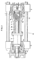
- the mold clamping apparatus 2 is provided with an ejector 1 mounted on a movable platen 3 which is slidable along tie bars 13.
- a first ball screw 8 extends parallel to the tie bars 13, between the movable platen 3 and a rear platen 10.
- the rear end portion of the first ball screw 8, on the side remote from the movable platen 3, is supported on the rear platen 10 so as to be rotatable and axially immovable relative thereto, by means of a radial bearing 14, a thrust bearing 15, and an angular bearing 16, which are disposed in a large-diameter stepped center hole 10a penetrating the central portion of the rear platen 10.
- a pulley 11 is fixed to the rear end of the first ball screw 8, which is operatively coupled to a mold clamping motor 100, fixed to the rear platen 10, by means of the pulley 11, a pulley 101 fixed to the output shaft of the motor 100, and a belt 102 stretched between these two pulleys (see Fig. 3).
- a first ball nut 9 mates with the first ball screw 8 so that it can reciprocate along the ball screw 8 as the ball screw 8 rotate forward or reversely.
- a pusher rod 12 for transmitting a driving force to the movable platen 3 is in the form of a hollow cylinder, and is disposed coaxial with the first ball screw 8.
- the rear and front ends of the rod 12 are coupled to the front end of the first ball nut 9 and the rear end face of a hollow cylindrical extension portion 3' of the movable platen 3, respectively.
- the first ball nut 9, the pusher rod 12, and the movable platen 3 are movable in one.
- the inside and outside diameters of the extension portion 3' are substantially equal to those of a spread portion of the rod 12.
- a large-diameter stepped bore 12a penetrates the pusher rod 12 along the axis thereof.
- the first screw 8 is loosely passed through the bore 12a.
- the axial length of the rod 12 or the bore 12a is set to a value equivalent to a required stroke of the movable platen 3 in order that the same platen can be moved through the required stroke.
- the movable platen extension portion 3' is penetrated by a bore 3'a which communicates with the bore 12a.
- the ejector 1 includes a second ball nut 7 and a second ball screw 6 mating therewith.
- the ball nut 7 is disposed in the bore 12a of the pusher rod 12 and the bore 3'a of the movable platen extension portion 3' so as to be coaxial with the first ball screw 8, and is supported by the rod 12 and the movable platen extension portion 3' with the aid of a bearing 17 so as to be rotatable and axially immovable.
- a hole 7a, which receives the front end portion of the first ball screw 8, is axially formed in the rear half portion of second ball nut 7, in order to reduce the axial length of the mold clamping apparatus 2.
- the second ball screw 6 is disposed in the bores 12a, 3'a and a hollow portion 3a of the movable platen 3 coaxially with the first ball screw 8.
- the rear end portion of the second ball screw 6 is removably fitted in a hole 8a axially formed in the front end portion of the ball screw 8, whereby the axial length of the mold clamping apparatus is reduced.
- the depth of the hole 8a is set to a value great enough to prevent the first and second ball screws 8 and 6 from interfering with each other when the movable platen 3 is situated in its mold opening end position, and therefore, when an ejector pin 4 is in its rearmost position.
- the ejector pin 4 is fixed to the front end portion of the second ball screw 6.
- the pin 4 is allowed to project and retreat from the front end face of the movable platen 3 through a hole 3b, which is bored through the front wall of the movable platen 3 and communicates with the hollow portion 3a of the movable platen.
- a stopper plate 18 is fixed to the rear end of the ejector pin 4.
- the plate 18 is supported in the hollow portion 3a of the movable platen 3 by means of two fixing pins 19 so as to be nonrotatable but axially movable, for preventing the ball screw 6 and the ejector pin 4 from rotating, but allowing them to move axially when the ball nut 7 rotates.
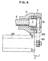
- a timing gear 7a is formed on the outer peripheral surface of the intermediate portion of the second ball nut 7.
- a timing belt 202 is stretched between the gear 7a and a timing gear 201, which is fixedly mounted on the output shaft of an ejector-use motor 200 fixed to the movable platen 3, whereby the ball nut 7 is operatively coupled to the motor 200.
- a notch 3'b through which the belt 202 is taken out is formed in that part of the peripheral wall of the movable platen extension portion 3' on the side of the motor 200.
- the mold clamping apparatus 2 is connected to a conventional control device (not shown) for controlling the drive of the mold clamping and ejector-use motors 100 and 200.
- the movable platen 3 is in the mold opening end position.
- the rear end portion of the second ball screw 6 is fitted in the hole 8a of the first ball screw 8, and is situated in its rearmost position, as shown in Fig. 1.
- This arrangement in conjunction with the arrangement in which the front end portion of the first ball screw 8 is fitted in the hole 7a of the second ball nut 7, allows the mold clamping apparatus 2 to be compact.
- the mold clamping motor 100 rotates forward in response to a mold clamping command from the control device, the pulley 11 and the first ball screw 8 rotate forward, thereby causing the first ball nut 9 to advance.
- the movable platen 3, which is integral with the ball nut 9 and the movable platen 3 advances, thereby performing mold closing operation and then mold clamping operation.
- a uniform mold clamping force is applied to the movable platen 3 through the pusher rod 12, which is coupled to the movable platen 3 through a circular ring-shaped junction plane.
- the ejector pin 4 along with the platen 3, advances, so that the rear end portion of the second ball screw 6, which is integral with the pin 4, gets out of the hole 8a of the first ball screw 8.
- mold opening operation is performed.
- the motor 100 reverses, the first ball screw 8 rotates reversely, so that the movable platen 3 retreats.
- the ejector-use motor 200 is rotated forward, thereby forwardly rotating the second ball nut 7 through the medium of the timing gears 7a and 201 and the timing belt 202.
- the second ball screw 6 and the ejector pin 4 advance, so that the pin 4 projects from the front end face of the movable platen 3, thereby pushing out a molding from a die (not shown) attached to the platen 3.
- the motor 200 is driven reversely to rotate the second ball nut 7 reversely, so that the ejector pin 4, which is integral with the second ball screw 6 mating with the nut 7, is retreated to the rearmost position shown in Fig. 1.
Landscapes
- Engineering & Computer Science (AREA)
- Manufacturing & Machinery (AREA)
- Mechanical Engineering (AREA)
- Moulds For Moulding Plastics Or The Like (AREA)
Abstract
Claims (7)
- Un appareil de serrage direct de moule comportant un éjecteur, comprenant un premier écrou à bille (9) relié à un élément de poussée creux (12), fixé à une platine mobile (3), de manière à ne pas pouvoir tourner par rapport audit élément de poussée (12) et mobile solidairement avec ledit élément de poussée (12), et une première vis à bille (8) qui est en prise par vissage avec le premier écrou à bille (9), s'étend à travers une partie creuse (12a) dudit élément de poussée (12) et peut tourner par l'intermédiaire d'une première source d'entraînement (100) afin d'effectuer une opération d'ouverture de moule et de fermeture de moule ;
ladite première vis à bille (8) présentant axialement un trou (8a) à une partie d'extrémité de celle-ci adjacente à la platine mobile (3) ;
ledit élément de poussée (12) étant accouplé à une partie centrale d'une face d'extrémité de ladite platine mobile (3), en regard dudit élément de poussée (12), par l'intermédiaire d'un plan de liaison sensiblement en forme de bague unique ; et
un éjecteur qui comprend : un second écrou à bille (7) porté dans une partie creuse (3a) de ladite platine mobile (3) de manière à pouvoir tourner tout en étant axialement immobile par rapport à ladite platine mobile (3) ; une seconde vis à bille (6) correspondant audit second écrou à bille (7) et placée en alignement axial avec ladite première vis à bille (8) et présentant, au niveau de son côté éloigné de ladite platine mobile (3), une partie d'extrémité de celle-ci placée de manière amovible dans ledit trou (8a) de ladite première vis à bille (6) ; un doigt éjecteur (4) fixé à l'autre partie d'extrémité de ladite seconde vis à bille (6), en regard de ladite platine mobile (3) et prévu pour faire saillie d'une face d'extrémité de ladite platine mobile (3) éloignée dudit élément de poussée (12) ; et une seconde source d'entraînement (200) reliée de manière fonctionnelle audit second écrou à bille (7). - Un appareil de serrage direct de moule comportant un éjecteur selon la revendication 1, dans lequel une partie d'extrémité dudit élément de poussée (12) en regard de ladite platine mobile (3) présente la forme d'un cylindre creux, et dans lequel ledit plan de jonction entre ledit élément de poussée (12) et ladite platine mobile (3) présente la forme d'une bague circulaire.
- Un appareil de serrage direct de moule comportant un éjecteur selon la revendication 1 ou 2, dans lequel ledit élément de poussée (12) présente la forme d'un cylindre creux et est disposé de manière coaxiale auxdits premier et second écrous à bille (9, 7) et auxdites première et seconde vis à bille (8, 6).
- Un appareil de serrage direct de moule comportant un éjecteur selon la revendication 1, 2 ou 3, dans lequel la longueur du trou (8a) formé dans ladite première vis à bille (8) est réglée à une valeur suffisamment grande pour empêcher que lesdites première et seconde vis à bille (8, 6) interfèrent l'une avec l'autre, même lorsque ladite seconde vis à bille (6) est située dans la position la plus arrière de celle-ci.
- Un appareil de serrage direct de moule comportant un éjecteur selon une revendication précédente quelconque, dans lequel ledit second écrou à bille (7) présente axialement, au niveau de sa partie d'extrémité opposée à ladite platine mobile (3), un trou (7a) prévu pour recevoir une partie d'extrémité de ladite première vis à bille (8) en regard de ladite platine mobile (3).
- Un appareil de serrage direct de moule comportant un éjecteur selon une revendication précédente quelconque, dans lequel lesdites première et seconde sources d'entraînement (100, 200) sont formées chacune d'un moteur.
- Un appareil de serrage direct de moule comportant un éjecteur selon une revendication précédente quelconque, dans lequel le second écrou à bille (7) est également porté dans la partie creuse (12a) de l'élément de poussée (12).
Applications Claiming Priority (2)
| Application Number | Priority Date | Filing Date | Title |
|---|---|---|---|
| JP241447/86 | 1986-10-13 | ||
| JP61241447A JPH06104329B2 (ja) | 1986-10-13 | 1986-10-13 | コアキシヤル・エジエクタ装置 |
Publications (3)
| Publication Number | Publication Date |
|---|---|
| EP0285672A1 EP0285672A1 (fr) | 1988-10-12 |
| EP0285672A4 EP0285672A4 (fr) | 1989-10-16 |
| EP0285672B1 true EP0285672B1 (fr) | 1992-09-02 |
Family
ID=17074441
Family Applications (1)
| Application Number | Title | Priority Date | Filing Date |
|---|---|---|---|
| EP87906608A Expired EP0285672B1 (fr) | 1986-10-13 | 1987-10-13 | Systeme de serrage hydraulique a pression directe et portant un ejecteur pour moule |
Country Status (5)
| Country | Link |
|---|---|
| US (1) | US4865536A (fr) |
| EP (1) | EP0285672B1 (fr) |
| JP (1) | JPH06104329B2 (fr) |
| DE (1) | DE3781545T2 (fr) |
| WO (1) | WO1988002687A1 (fr) |
Families Citing this family (24)
| Publication number | Priority date | Publication date | Assignee | Title |
|---|---|---|---|---|
| JPH0745160B2 (ja) * | 1987-10-24 | 1995-05-17 | ファナック株式会社 | 射出圧縮成形機における圧縮装置 |
| JPH084911B2 (ja) * | 1989-01-30 | 1996-01-24 | 宇部興産株式会社 | 成形機用型締装置 |
| JPH03278929A (ja) * | 1990-03-29 | 1991-12-10 | Fanuc Ltd | 射出成形機のイジェクタ機構 |
| US5139411A (en) * | 1991-04-01 | 1992-08-18 | Polacinski Michel C | Apparatus for reducing wear on mold ejection systems |
| GB2273175B (en) * | 1992-12-04 | 1996-05-15 | Advanced Systems Automation Pt | Direct drive electro-mechanical press for encapsulating semiconductor devices |
| DE4228140A1 (de) * | 1992-08-25 | 1994-03-03 | Battenfeld Kunststoffmasch | Auswerfereinheit für Spritzgießmaschinen |
| EP0674985B1 (fr) * | 1994-04-02 | 1999-08-11 | Karl Hehl | Unité de fermeture de moule pour une machine à mouler par injection et procédé pour son opération |
| JP2838978B2 (ja) * | 1995-02-03 | 1998-12-16 | 住友重機械工業株式会社 | エジェクタ装置 |
| US6154942A (en) * | 1997-09-26 | 2000-12-05 | Tesco Engineering, Inc. | Closure panel hemming apparatus |
| AT406247B (de) * | 1997-10-24 | 2000-03-27 | Engel Gmbh Maschbau | Auswerfereinheit für eine spritzgiessmaschine |
| DE19750057C2 (de) * | 1997-11-12 | 2000-08-03 | Karl Hehl | Formschließeinheit für eine Spritzgießmaschine |
| JP3240352B2 (ja) * | 1998-10-20 | 2001-12-17 | 日精樹脂工業株式会社 | 電動式射出成形機 |
| US6315544B1 (en) | 1999-10-07 | 2001-11-13 | Burger Engineering, Inc. | Adjustable length extension bars for connecting a mold ejector plate to a press ejector plate |
| DE10022192A1 (de) * | 2000-05-03 | 2001-11-15 | Mannesmann Ag | Einrichtung zum Entfernen von Spritzgießteilen |
| JP3394516B2 (ja) * | 2000-10-06 | 2003-04-07 | エヌイーシーセミコンダクターズ九州株式会社 | 樹脂封止金型 |
| DE10123104A1 (de) * | 2001-05-12 | 2002-11-14 | Mannesmann Plastics Machinery | Formaufspannplatte für eine Spritzgießmaschine, sowie eine Zwei-Platten-Spritzgießmaschine hiermit |
| CA2422638A1 (fr) * | 2002-04-25 | 2003-10-25 | Conix Corporation | Mecanisme et methode de verrouillage du moule secondaire |
| US20070237851A1 (en) * | 2006-04-10 | 2007-10-11 | Baron Frank D R | Two platen traverse cylinder mounting system |
| CA2607397A1 (fr) * | 2007-10-23 | 2009-04-23 | Husky Injection Molding Systems Ltd. | Ejecteur pour l'ejection de piece hors d'un moule |
| WO2009079748A1 (fr) * | 2007-12-20 | 2009-07-02 | Husky Injection Molding Systems Ltd. | Ensemble éjecteur pour éjection de pièces moulées |
| WO2009144777A1 (fr) * | 2008-05-26 | 2009-12-03 | 住友重機械工業株式会社 | Dispositif de serrage de moule |
| US8297967B2 (en) * | 2010-03-16 | 2012-10-30 | Acumen Co., Ltd. | Ejector device for an injection molding machine |
| CN104219885B (zh) | 2013-05-31 | 2017-05-10 | 国际商业机器公司 | 用于锁销焊接型部件的温度触发顶出系统和返修方法 |
| CN117067511B (zh) * | 2023-07-04 | 2024-01-16 | 扬州市迪凯精密科技有限公司 | 一种模具加工装置及其方法 |
Family Cites Families (3)
| Publication number | Priority date | Publication date | Assignee | Title |
|---|---|---|---|---|
| US4230442A (en) * | 1979-08-21 | 1980-10-28 | Husky Injection Molding Systems Limited | Mold-clamping mechanism for injection-molding machine |
| CA1196458A (fr) * | 1981-10-08 | 1985-11-12 | Yoshihiko Yamazaki | Machine a mouler par injection |
| JPS5924311U (ja) * | 1982-08-09 | 1984-02-15 | 日精樹脂工業株式会社 | 成形品突出し機構を有する型締装置 |
-
1986
- 1986-10-13 JP JP61241447A patent/JPH06104329B2/ja not_active Expired - Lifetime
-
1987
- 1987-10-13 WO PCT/JP1987/000767 patent/WO1988002687A1/fr not_active Ceased
- 1987-10-13 US US07/221,251 patent/US4865536A/en not_active Expired - Fee Related
- 1987-10-13 DE DE8787906608T patent/DE3781545T2/de not_active Expired - Fee Related
- 1987-10-13 EP EP87906608A patent/EP0285672B1/fr not_active Expired
Also Published As
| Publication number | Publication date |
|---|---|
| EP0285672A1 (fr) | 1988-10-12 |
| WO1988002687A1 (fr) | 1988-04-21 |
| JPH06104329B2 (ja) | 1994-12-21 |
| EP0285672A4 (fr) | 1989-10-16 |
| US4865536A (en) | 1989-09-12 |
| DE3781545T2 (de) | 1993-02-18 |
| DE3781545D1 (de) | 1992-10-08 |
| JPS6395925A (ja) | 1988-04-26 |
Similar Documents
| Publication | Publication Date | Title |
|---|---|---|
| US4865536A (en) | Direct mold clamping apparatus with ejector | |
| US5129808A (en) | Two-plate type injection apparatus | |
| EP0213211B1 (fr) | Structure de serrage de moule pour machines de moulage par injection | |
| EP0752303B1 (fr) | Mecanisme d'injection pour machines de moulage par injection | |
| KR101135556B1 (ko) | 성형기 | |
| US5238394A (en) | Mold clamping apparatus for molding apparatus | |
| US3510915A (en) | Injection molding machine pressure balanced drive shaft | |
| US6796787B2 (en) | Product ejecting apparatus and method for an injection molding machine | |
| EP1741538B1 (fr) | Unité d'injection pour une machine de moulage par injection | |
| US6179607B1 (en) | Two-platen mold-clamping apparatus | |
| JPH0929802A (ja) | 射出成形機の型締装置 | |
| US3509601A (en) | Injection molding machine | |
| JP3034827B2 (ja) | ロッド回動式シリンダ装置 | |
| CN1997498B (zh) | 驱动装置 | |
| US4906173A (en) | Compressor unit in an injection-compression molding machine | |
| JP2002200658A (ja) | 射出成形機の型締め装置 | |
| JPH1034714A (ja) | 射出成形機の射出ユニット | |
| JP2875220B2 (ja) | シリンダ装置 | |
| WO2019191846A1 (fr) | Appareil de serrage compact ayant un dispositif d'actionnement de rupture de moule intégrée à force élevée | |
| JPS6227382Y2 (fr) | ||
| JP2001121588A (ja) | 射出成形機におけるエジェクター装置 | |
| CN112620608B (zh) | 一种用于压铸设备的锁模装置 | |
| JP2610194B2 (ja) | スライドコア付き金型 | |
| US4438539A (en) | Actuator for generating tool head | |
| JPH11115009A (ja) | 射出成形機の型締装置 |
Legal Events
| Date | Code | Title | Description |
|---|---|---|---|
| PUAI | Public reference made under article 153(3) epc to a published international application that has entered the european phase |
Free format text: ORIGINAL CODE: 0009012 |
|
| 17P | Request for examination filed |
Effective date: 19880629 |
|
| AK | Designated contracting states |
Kind code of ref document: A1 Designated state(s): CH DE FR GB IT LI |
|
| A4 | Supplementary search report drawn up and despatched |
Effective date: 19891016 |
|
| 17Q | First examination report despatched |
Effective date: 19910226 |
|
| ITF | It: translation for a ep patent filed | ||
| GRAA | (expected) grant |
Free format text: ORIGINAL CODE: 0009210 |
|
| AK | Designated contracting states |
Kind code of ref document: B1 Designated state(s): CH DE FR GB IT LI |
|
| PG25 | Lapsed in a contracting state [announced via postgrant information from national office to epo] |
Ref country code: LI Effective date: 19920902 Ref country code: FR Effective date: 19920902 Ref country code: CH Effective date: 19920902 |
|
| REF | Corresponds to: |
Ref document number: 3781545 Country of ref document: DE Date of ref document: 19921008 |
|
| REG | Reference to a national code |
Ref country code: CH Ref legal event code: PL |
|
| EN | Fr: translation not filed | ||
| PLBE | No opposition filed within time limit |
Free format text: ORIGINAL CODE: 0009261 |
|
| STAA | Information on the status of an ep patent application or granted ep patent |
Free format text: STATUS: NO OPPOSITION FILED WITHIN TIME LIMIT |
|
| 26N | No opposition filed | ||
| PGFP | Annual fee paid to national office [announced via postgrant information from national office to epo] |
Ref country code: GB Payment date: 19981016 Year of fee payment: 12 Ref country code: DE Payment date: 19981016 Year of fee payment: 12 |
|
| PG25 | Lapsed in a contracting state [announced via postgrant information from national office to epo] |
Ref country code: GB Free format text: LAPSE BECAUSE OF NON-PAYMENT OF DUE FEES Effective date: 19991013 |
|
| GBPC | Gb: european patent ceased through non-payment of renewal fee |
Effective date: 19991013 |
|
| PG25 | Lapsed in a contracting state [announced via postgrant information from national office to epo] |
Ref country code: DE Free format text: LAPSE BECAUSE OF NON-PAYMENT OF DUE FEES Effective date: 20000801 |
|
| PG25 | Lapsed in a contracting state [announced via postgrant information from national office to epo] |
Ref country code: IT Free format text: LAPSE BECAUSE OF NON-PAYMENT OF DUE FEES;WARNING: LAPSES OF ITALIAN PATENTS WITH EFFECTIVE DATE BEFORE 2007 MAY HAVE OCCURRED AT ANY TIME BEFORE 2007. THE CORRECT EFFECTIVE DATE MAY BE DIFFERENT FROM THE ONE RECORDED. Effective date: 20051013 |