EP0285705A2 - Verstärkungen für das kontinuierliche Ziehen von aus verstärkten Kunststoffen bestehenden Produkten und neue, durch Pultrusion hergestellte Produkte - Google Patents
Verstärkungen für das kontinuierliche Ziehen von aus verstärkten Kunststoffen bestehenden Produkten und neue, durch Pultrusion hergestellte Produkte Download PDFInfo
- Publication number
- EP0285705A2 EP0285705A2 EP87118798A EP87118798A EP0285705A2 EP 0285705 A2 EP0285705 A2 EP 0285705A2 EP 87118798 A EP87118798 A EP 87118798A EP 87118798 A EP87118798 A EP 87118798A EP 0285705 A2 EP0285705 A2 EP 0285705A2
- Authority
- EP
- European Patent Office
- Prior art keywords
- mat
- mats
- strands
- resin
- fibers
- Prior art date
- Legal status (The legal status is an assumption and is not a legal conclusion. Google has not performed a legal analysis and makes no representation as to the accuracy of the status listed.)
- Granted
Links
Images


Classifications
-
- B—PERFORMING OPERATIONS; TRANSPORTING
- B29—WORKING OF PLASTICS; WORKING OF SUBSTANCES IN A PLASTIC STATE IN GENERAL
- B29D—PRODUCING PARTICULAR ARTICLES FROM PLASTICS OR FROM SUBSTANCES IN A PLASTIC STATE
- B29D99/00—Subject matter not provided for in other groups of this subclass
- B29D99/0003—Producing profiled members, e.g. beams
-
- B—PERFORMING OPERATIONS; TRANSPORTING
- B29—WORKING OF PLASTICS; WORKING OF SUBSTANCES IN A PLASTIC STATE IN GENERAL
- B29C—SHAPING OR JOINING OF PLASTICS; SHAPING OF MATERIAL IN A PLASTIC STATE, NOT OTHERWISE PROVIDED FOR; AFTER-TREATMENT OF THE SHAPED PRODUCTS, e.g. REPAIRING
- B29C70/00—Shaping composites, i.e. plastics material comprising reinforcements, fillers or preformed parts, e.g. inserts
- B29C70/04—Shaping composites, i.e. plastics material comprising reinforcements, fillers or preformed parts, e.g. inserts comprising reinforcements only, e.g. self-reinforcing plastics
- B29C70/06—Fibrous reinforcements only
- B29C70/08—Fibrous reinforcements only comprising combinations of different forms of fibrous reinforcements incorporated in matrix material, forming one or more layers, and with or without non-reinforced layers
- B29C70/083—Combinations of continuous fibres or fibrous profiled structures oriented in one direction and reinforcements forming a two dimensional structure, e.g. mats
- B29C70/085—Combinations of continuous fibres or fibrous profiled structures oriented in one direction and reinforcements forming a two dimensional structure, e.g. mats the structure being deformed in a three dimensional configuration
-
- B—PERFORMING OPERATIONS; TRANSPORTING
- B29—WORKING OF PLASTICS; WORKING OF SUBSTANCES IN A PLASTIC STATE IN GENERAL
- B29C—SHAPING OR JOINING OF PLASTICS; SHAPING OF MATERIAL IN A PLASTIC STATE, NOT OTHERWISE PROVIDED FOR; AFTER-TREATMENT OF THE SHAPED PRODUCTS, e.g. REPAIRING
- B29C70/00—Shaping composites, i.e. plastics material comprising reinforcements, fillers or preformed parts, e.g. inserts
- B29C70/04—Shaping composites, i.e. plastics material comprising reinforcements, fillers or preformed parts, e.g. inserts comprising reinforcements only, e.g. self-reinforcing plastics
- B29C70/28—Shaping operations therefor
- B29C70/40—Shaping or impregnating by compression not applied
- B29C70/50—Shaping or impregnating by compression not applied for producing articles of indefinite length, e.g. prepregs, sheet moulding compounds [SMC] or cross moulding compounds [XMC]
- B29C70/52—Pultrusion, i.e. forming and compressing by continuously pulling through a die
- B29C70/525—Component parts, details or accessories; Auxiliary operations
-
- Y—GENERAL TAGGING OF NEW TECHNOLOGICAL DEVELOPMENTS; GENERAL TAGGING OF CROSS-SECTIONAL TECHNOLOGIES SPANNING OVER SEVERAL SECTIONS OF THE IPC; TECHNICAL SUBJECTS COVERED BY FORMER USPC CROSS-REFERENCE ART COLLECTIONS [XRACs] AND DIGESTS
- Y10—TECHNICAL SUBJECTS COVERED BY FORMER USPC
- Y10T—TECHNICAL SUBJECTS COVERED BY FORMER US CLASSIFICATION
- Y10T428/00—Stock material or miscellaneous articles
- Y10T428/23907—Pile or nap type surface or component
- Y10T428/2395—Nap type surface
-
- Y—GENERAL TAGGING OF NEW TECHNOLOGICAL DEVELOPMENTS; GENERAL TAGGING OF CROSS-SECTIONAL TECHNOLOGIES SPANNING OVER SEVERAL SECTIONS OF THE IPC; TECHNICAL SUBJECTS COVERED BY FORMER USPC CROSS-REFERENCE ART COLLECTIONS [XRACs] AND DIGESTS
- Y10—TECHNICAL SUBJECTS COVERED BY FORMER USPC
- Y10T—TECHNICAL SUBJECTS COVERED BY FORMER US CLASSIFICATION
- Y10T428/00—Stock material or miscellaneous articles
- Y10T428/23907—Pile or nap type surface or component
- Y10T428/23979—Particular backing structure or composition
Definitions
- the present invention relates to novel fiber reinforcements used in preparing resin reinforced articles in a pultrusion process. More particularly, the present invention relates to pultruded resin articles which are reinforced with mats and fibers in unique orientations to enhance surface characteristics and tensile strengths. Still more particularly, the present invention relates to novel combinations of mechanically-bonded continuous strand mats; and in particular, to needled continuous strand mats in which at least one mat has non-chemically bonded continuous strands, and that mat is needled to a second continuous strand mat in which the continuous strands are bound to each other either chemically or mechanically and these mats are used with other reinforcing strands to produce resin articles of enhanced appearance and/or strength.
- reinforcement mats are provided for use in pultrusion molding of parts that are combinations of at least two mats held together by a mechanical bonding process; i.e., needling with barbed needles to provide a composite mat that will withstand the pulling forces encountered during pultrusion without damage.
- a pultruded article is formed which is reinforced with a plurality of strands sandwiched between reinforcing mats each of which is formed from at least two continuous strand mats.
- a continuous strand mat is needled to a bonded scrim cloth to provide a scrim-mat composite reinforcement for use in a pultrusion process.
- two composite mats each containing two continuous strand mats are needled together to provide a spiked side and a non-spiked side in the composite mats.
- the mats are fed into a die in which reinforcing strands are being fed between the two mats in the die.
- the mats are further placed in the die so that the spiked sides of both mats face inward toward the surface of the strands being fed between the mats.
- This embodiment of the invention is a preferred mode of operation where enhanced flexural and tensile strength are desired in the pultruded articles.
- high density needled continuous strand mat preferably of glass fiber strands with the mat having a density of at least 0.75 ounces per square foot or more is used in lieu of either a composite needled mat or a chemically bonded mat for producing a pultruded article.
- the spiked sides of the high density mats used are positioned so that they face toward each other in the article being pultruded to produce parts having enhanced surface characteristics. This is a preferred embodiment where small sharp protrusions, ridges and the like in the pultruded part require a more complete filling thereof with reinforcement for enhanced strength.
- a composite mat is utilized in reinforcing the resin articles that are to be pultruded to form the novel articles of manufacture.
- Composite mats produced in accordance with the instant invention are composed of a light weight continuous surface mat and a continuous strand reinforcing mat. Both mats are characterized by having the fibers randomly distributed throughout the mat.
- the continuous strand reinforcement mats which are coupled to the continuous strand or filament surface mats are preferably constructed of glass fibers. While composite mats are preferred, it is within the scope of the invention to use a needled continuous strand mat alone provided it has a high density.
- high density is meant a continuous strand reinforcement mat having a density of at least 0.75 ounces per square foot or more, preferably 1.5 ounces per square foot. Generally high density continuous strand mats ranging in density between 0.75 to two ounces or more are useful. In instances where reinforcement mats of this type are used, continuous glass strand mats are preferred.
- the fiber size can range widely between a fiber strand which is composed of filaments ranging from a DE filament to a T filament or higher.
- the filament size ranges from 20 ⁇ 10 ⁇ 5 to 95 ⁇ 10 ⁇ 5 inches.
- the filaments are generally in the range of 35 to 40 ⁇ 10 ⁇ 5 inches.
- the fibers In the surfacing mats utilized when the surfacing mat is composed of fiber glass, the fibers generally range in size with those above mentioned.
- Surfacing mats of natural or synthetic fibers having similar fiber diameters or even larger diameters may be employed in lieu of glass fiber mats.
- “Scrim” as used herein means an open weave cloth of synthetic or natural fiber strands having at least four holes per square inch of cloth formed by the weave.
- the term "chemically bound” is utilized in the application and in the claims with respect to fiber strands in mats, the term is meant to include a bonding of the fiber strands one to the other by utilization of a chemical bonding agent such as a thermoplastic or a thermoset resin.
- a chemical bonding agent such as a thermoplastic or a thermoset resin.
- the surface mats it is often common practice to join the fiber strands forming the mat to each other by mixing strands of different melting points together and melting one of the strands to accomplish the bonding.
- bonding is accomplished by utilizing thermoplastic resins or thermoset resins which effectively bond the strands one to the other in the mat being constructed to provide integrity to the mat.
- the particular size employed in the mats and fiber strands utilized to reinforce the resin article herein will be determined, therefore, by the resin system utilized in forming the article. Once the resin has been determined with respect to the article that is to be produced, glass manufacturers and synthetic fiber manufacturers can readily supply a resin compatible strand for utilization as reinforcement with that particular resin system.
- the resin systems utilized in producing the articles of the instant invention may be neat or they may be filled.
- the resins contain fillers in varying amounts.
- the fillers are present in amounts ranging from a trace amount to 30 percent, preferably 10 to 25 percent and most preferably 15 percent.
- the fillers may be any suitable filler utilized by the art to fill a resin system of the type being produced.
- fillers such as calcium carbonate, titanium dioxide, silicon dioxide, carbon black and the like may be used.
- needles of various types may be utilized to accomplish the combining of the surface mat with the major fiber glass strand mat or to needle together the strands used to form the high density strand mats.
- Needles ranging from 15 gauge needles to 32 gauge are certainly acceptable depending on the qualities desired in the final mat product.
- This same 25 guage needle is used in the preparation of high density glass mats from glass fiber strands.
- strand means, as used herein, a multiplicity of filaments combined together and can include rovings as that term is generally understood by the skilled artisan, i.e., a plurality of strands combined mechanically on a roving winder.
- Direct draw rovings of the type shown in U.S. Patent 4,509,702 are also encompassed by this term.
- spikes utilized herein the specification shall mean a dense major surface of the needled composite mat or the high density needled mat which contains a multiplicity of the elongated filaments and/or fibers or strands projecting from the surface outwardly.
- the filaments, fibers and/or strands projecting from the surface of the mat on the spiked surface thereof are referred to herein as spikes.
- non-spiked surface means a less densely spiked major surface of the same mat that contains a spiked surface.
- thermoset resins The resin materials that may be utilized in preparing the articles of the instant invention are generally speaking thermoset resins and the preferred embodiments of the invention incorporate utilization of unsaturated polyester thermoset resins.
- thermoplastic resins both as homopolymers and copolymers may be utilized in preparing articles in utilizing pultrusion techniques.
- polyester resins as far as the thermoset resins are concerned, they can be aldehyde condensate resins and unsaturated polyester such as vinylesters, epoxies, phenolic resins, alkyd resins, silicone resins and diallyl phthalate homopolymers and polyamide, urea and melamine containing resins and polyurethanes to mention just a few.
- thermoplastic resins materials may be utilized which are vinyl resins formed by the polymerization of vinyl halides or by the copolymerization of vinyl halides with unsaturated polymerized compounds such as vinyl esters; alpha, beta-unsaturated acids; alpha, beta-unsaturated esters; alpha, beta-unsaturated ketones; alpha, beta-unsaturated aldehydes and unsaturated hydrocarbons such as butadienes and styrenes; poly-alpha-olefins such as polyethylene, polypropylene, polybutylene, polyisoprene and the like including copolymers of poly-alpha-olefins; phenoxy resins; polyamides such as polyhexamethylene adipamide; polysulfones; polycarbonates; polyacetyls; polyethylene oxide; polystyrene, including copolymers of styrene with monomeric compounds such as acrylonitrile and butadiene;
- the fibers, strands and or filaments referred to herein, except for those specifically excluded by the claim terminology, are intended to include synthetic fibers such as polyester fibers, thermoplastic fibers such as polypropylenes, polyphenylene sulfide fibers, nylons, ORLON®, DACRON® and other similar materials.
- Natural fibers as used herein is meant to include cotton, wool, linen, jute and the like.
- “Inorganic fibers” is intended to include glass fibers, carbon fibers, ceramic fibers and the like.
- a mat 62 Prior to feeding the strands 4, 5, 6, and 7 to the conveyer 2, a mat 62 is fed from a roll 60 of that material 60 across a feed roller 61 and onto the surface of the conveyor 2. With this arrangement, the mat 62 is of the desired width of the final product or something slightly larger and the strands 4, 5, 6, and 7 as they traverse across the width of the conveyer 2 and the mat 62 contained thereon lay down between the edges of the mat 62 a loose mat of continuous strands.
- the strands 4, 5, 6, and 7 laid down on the mat 62 pass forwardly to a needler generally indicated at 50.
- a needle board 51 containing barbed needles 52 therein is designed to mesh with apertures 56 coinciding with the positioning of the needles 52.
- the plate 55 having apertures 56 is stationery and mounted in a suitable housing 59 and needle board 51 in operation reciprocates in a vertical direction.
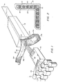
- Figure 1 there is shown a pultrusion process which is designed to combine mats 64 of the type formed in the machinery of Figure 5, whether they are composite mats or high density mats, with suitable reinforcement strands.
- Figure 1 shows continuous strands 70 being drawn from a plurality of packages generally indicated at 71.
- Strands 70 which can also be rovings, are drawn through a container 73 which is filled with a polyester resin material 74.
- Strands 70 are drawn through the resin bath 73 from one end to the other under rods not shown in the drawing but located along the bottom of the resin bath 73 so that the strands 70 are totally immersed in the resin. Soaked strands 70 are then passed into the aperture 75 of an elongated die 76 which is typically heated along its length.
- Mat 77 has a fold 79 in the center thereof
- mat 76 has a fold 80 in the center thereof.
- the fold in 79 divides mat 77 into two halves as 77a and 77b and the fold 80 in mat 78 divided that mat into two folds 78a and 78b.
- the mats 77 and 78 being fed to the die may be previously immersed in the same polyester resin that the fibers 70 have been immersed in the same container 73 or in another container but need not be so immersed. When not immersed in resin, the mats 77 and 78 obtain sufficient resin for impregnation thereof through contact with the resin rich strands 70.
- the mats 77 and 78 and the resin impregnated strands 70 form a sandwich arrangement in the die so that the strands 70 are completely surrounded in the die on all surfaces by a portion of either mat 77 or 78.
- the combination of mats 77 and 78 and rovings 70 together with the resins impregnated all over them passes through the die from the inlet end to the exit end.
- the mats, rovings and resin are heated during their passage through the die to temperatures sufficient to cause the resin contained in the die to cure. Thus, a solid product is formed and is removed from the exit end of the die.
- the resin employed in the pultrusion process were a thermoplastic resin as opposed to the thermoset resin of the preferred embodiments, obviously the mats 77 and 78 and the strands 70 would be impregnated with molten thermoplastic immediately prior to being introduced into the die opening 75. Rather than being heated along its length, the die 76 would be cooled along its length so that the thermoplastic resin would solidify during its passage through the die to form a finished part 81, a major component of which would be a thermoplastic resin.
- Figure 2 is a cross section of the part 81 of Figure 1 showing the strands or rovings 70, the mats 77 and 78 and the orientation of the spiked surface 83 of mat 77 and the spiked surface 84 of mat 78 in one of the preferred embodiments.
- the finished product which in this instance as shown in the drawing, is a complex patio sliding door jamb possesses many complex shapes and curvatures thereon.
- Both of the mats 77 and 78 and the rovings 70 sandwiched between the mats 77 and 78 are positioned such that the spikes on the mat surfaces 83 and 84 are facing inwardly towards the roving 70 in a part having such complex grooves and ridges.
- a mat 46 inches wide was prepared as follows using this equipment.
- Two feeders were employed to feed fiber glass strands to the surface of a conveyor moving in a direction generally at an angle normal to the angle at which the strands were being fed to the surface thereof.
- the feeder was operated at a speed to provide strand speeds of 1175 feet per minute.
- the strands passed downwardly onto the surface of a horizontally moving conveyor chain. Eight strands were fed to each feeder, each set of strands containing 800 filaments.
- the strands were traversed back and forth across the moving conveyor at a rate of 1 cycle every 6.5 seconds, a single traverse over and back being one cycle.
- a Remay® polyester surfacing mat manufactured by E. I. DuPont having a mat density of 1.35 ounces per square yard.
- Fiber glass strands which were placed on the surfacing mat contained a size having polyester resin compatible ingredients.
- the size composition used contained a polyester resin film former, a glycidol propyltrimethoxy silane coupling agent, a fatty acid lubricant and acetic acid.
- the amount of size on the glass fibers was 0.9 percent by weight basis the weight of the glass.
- the mat After passing across the conveyor, the mat was passed into a needling machine which had 25 gauge needles therein reciprocating in a vertical direction as the mat passed through the needler.
- the needles and needle boards utilized provided 150 needle penetrations per square inch in the finished mat and the needles passed through the bottom orifices in the base plate of the needler to a depth of about 0.8 inches.
- the barbed needles which have the barbs pointed in a downward direction, caught the glass fibers and passed them through the polyester mat to a depth of about 0.8 inches on the downward stroke.
- This mat was removed from the needling machine and is typically 1 ounce per square foot in density.
- Glass fiber strands having filaments in a diameter range of 90-95 ⁇ 10 ⁇ 5 inches and wherein each of the strands contains 4,000 filaments are passed through a resin bath of Koppers Co. B753-118 unsaturated polyester resin having 15 percent calcium carbonate therein to thoroughly saturate the strands and filaments contained therein with the polyester resin.
- the rovings are fed to a pultrusion die and the mats are then passed into the pultrusion die on the outside of the rovings as shown in Figure 1 herein.
- the die is an elongated die having a central opening conforming to a configuration such as shown in Figure 3.
- the die is approximately 40 inches in length and is clamped along its length between two resistance heated plates which are individually controlled to provide a temperature gradient from the inlet end of the die to the outlet end thereof.
- the rovings and the mats passing through the die pass through it at a rate of approximately 3 to 4 feet per minute, and the die is heated at the entrance to a temperature of about 200°F.
- the center of the die operates at a temperature of approximately 390°F and the exit of the die at approximately 350°F.
- the parts flowing through the die are roughly 40-45 percent resin with 55-60 percent of the remainder being glass reinforcements.
- the resin itself is 70 percent polyester and 30 percent filler and other additives such as coloring agents, catalysts and the like.
- the parts removed are cut into appropriate lengths for use as door jambs.
- the strands were traversed back and forth across the moving conveyor at a rate of 1 cycle every 6.5 seconds. A single traverse over and back being one cycle.
- the moving conveyor was traveling at a speed of 4 feet per minute.
- the strand speed and quantities of strand coupled with the conveyor speed produced a mat having a density of 1.5 ounces per square foot.
- the fiber glass strands introduced onto the conveyor contained a size having polyester resin compatible ingredients.
- the strands thus contained a coating or size thereon comprised primarily of a polyvinylacetate film former, a gamma-aminopropyltriethoxy silane, a vinyl triacetoxy silane, a fatty acid lubricant, ammonium chloride, a melamine-formaldehyde curing agent and a quaternary ammonium lubricating agent.
- the amount of size on the glass fibers was 0.9 percent by weight basis the weight of the glass.
- the mat After passing across the conveyor, the mat was passed into a needling machine which had 25 gauge needles therein reciprocating in a vertical direction as the mat passed through the needler.
- the needles and needle boards utilized provided 315 needle penetrations per square inch in the finished mat and the needles passed through the bottom orifices in the base plate of the needler to a depth of about 0.65 inches.
- the barbed needles which have the barbs pointed in a downward direction, catch the glass fibers from the top surface and the inside of the mat and pass them through the bottom of the mat to a depth of about 0.65 inches on the downward stroke.
- Glass fiber strands having filaments in a diameter range of 90-95 ⁇ 10 ⁇ 5 inches and wherein each of the strands contains 4,000 filaments are passed through a resin bath of Koppers Co. B753-118 unsaturated polyester resin having 15 percent calcium carbonate therein to thoroughly saturate the strands and filaments contained therein with the polyester resin.
- the rovings are fed to a pultrusion die and two mats produced as in Example 3 are then passed into the pultrusion die on the outside of the rovings as shown in Figure 1 herein.
- the die is an elongated die having a central opening conforming to a configuration such as shown in Figure 3.
- the die is approximately 40 inches in length and is clamped along its length between two resistance heated plates which are individually controlled to provide a temperature gradient from the inlet end of the die to the outlet end.
- the rovings and the mats passing through the die pass through it at a rate of approximately 3 to 4 feet per minute, and the die is heated at the entrance to a temperature of about 200°F.
- the center of the die operates at a temperature of approximately 390°F and the exit of the die at approximately 350°F.
- the parts flowing through the die are roughly 40-45 percent resin with 55-60 percent of the remainder being glass reinforcements.
- the resin itself is 70 percent polyester and 30 percent filler and other additives such as coloring agents, catalysts and the like.
- the parts removed are cut into appropriate lengths for use as door jambs.
- the above examples are illustrations of preferred methods of providing the articles of the instant invention and the reinforcement mats to be utilized with such articles.
- window and door framing materials can be produced readily from a system of this type.
- the mats and the articles of manufacture herein described find a variety of uses where reinforcement is required in all directions and superior reinforcement is required in a single direction.
- the parts are particularly useful where it is also important that the surface characteristics of the finished part be such that they present smooth surfaces.
- the parts further are characterized by being extremely resistance to delamination of the surface reinforcements under stress.
Landscapes
- Engineering & Computer Science (AREA)
- Mechanical Engineering (AREA)
- Chemical & Material Sciences (AREA)
- Composite Materials (AREA)
- Reinforced Plastic Materials (AREA)
- Nonwoven Fabrics (AREA)
- Moulding By Coating Moulds (AREA)
- Laminated Bodies (AREA)
Applications Claiming Priority (4)
| Application Number | Priority Date | Filing Date | Title |
|---|---|---|---|
| US3415987A | 1987-04-09 | 1987-04-09 | |
| US34159 | 1987-04-09 | ||
| US07/074,665 US4752513A (en) | 1987-04-09 | 1987-07-17 | Reinforcements for pultruding resin reinforced products and novel pultruded products |
| US74665 | 1987-07-17 |
Publications (3)
| Publication Number | Publication Date |
|---|---|
| EP0285705A2 true EP0285705A2 (de) | 1988-10-12 |
| EP0285705A3 EP0285705A3 (en) | 1989-10-18 |
| EP0285705B1 EP0285705B1 (de) | 1991-09-11 |
Family
ID=26710631
Family Applications (1)
| Application Number | Title | Priority Date | Filing Date |
|---|---|---|---|
| EP19870118798 Expired - Lifetime EP0285705B1 (de) | 1987-04-09 | 1987-12-18 | Verstärkungen für das kontinuierliche Ziehen von aus verstärkten Kunststoffen bestehenden Produkten und neue, durch Pultrusion hergestellte Produkte |
Country Status (4)
| Country | Link |
|---|---|
| US (1) | US4752513A (de) |
| EP (1) | EP0285705B1 (de) |
| JP (1) | JPS63257625A (de) |
| DE (1) | DE3772975D1 (de) |
Cited By (4)
| Publication number | Priority date | Publication date | Assignee | Title |
|---|---|---|---|---|
| US5665451A (en) * | 1993-10-12 | 1997-09-09 | Textilma Ag | Textile insert for producing a fibrous composite material and fibrous composite material comprising such a textile insert |
| EP0867270A1 (de) * | 1997-03-28 | 1998-09-30 | Andersen Corporation | Verbundwerkstoff aus thermoplastischen Harz mit Glasfasergewebe und Verfahren |
| DE102015203315A1 (de) * | 2015-02-24 | 2016-08-25 | Bayerische Motoren Werke Aktiengesellschaft | Pultrusionsverfahren zur Herstellung von faserverstärkten Kunststoffprofilen |
| DE102015203313A1 (de) * | 2015-02-24 | 2016-08-25 | Bayerische Motoren Werke Aktiengesellschaft | Pultrusionsverfahren zur Herstellung von faserverstärkten Kunststoffprofilen |
Families Citing this family (74)
| Publication number | Priority date | Publication date | Assignee | Title |
|---|---|---|---|---|
| US4983453A (en) * | 1987-09-04 | 1991-01-08 | Weyerhaeuser Company | Hybrid pultruded products and method for their manufacture |
| US4812343A (en) * | 1988-01-27 | 1989-03-14 | W. H. Brady Co. | Pultruded fiber reinforced plastic marking devices |
| US4935279A (en) * | 1988-01-27 | 1990-06-19 | W. H. Brady Co. | Pultruded composite sign and process therefor |
| US5066349A (en) * | 1988-01-27 | 1991-11-19 | W. H. Brady Co. | Process for pultruding a composite sign |
| GB8822520D0 (en) * | 1988-09-26 | 1988-11-02 | Tech Textiles Ltd | Process for continuously forming reinforced plastics articles |
| US4938823A (en) * | 1988-10-07 | 1990-07-03 | The Pultrusions Corporation | Pultrusion/extrusion method |
| US5176865A (en) * | 1988-10-13 | 1993-01-05 | Weyerhaeuser Company | Pultrusion method for condensation resin injection |
| DE3901152A1 (de) * | 1989-01-17 | 1990-07-19 | Hoechst Ag | Flammfeste traegerbahn fuer bitumenbahnen und verfahren zu ihrer herstellung |
| US5169699A (en) * | 1990-05-21 | 1992-12-08 | Avista Industries, Inc. | Reinforcing substrate structures with decorative surface layer |
| US5350603A (en) * | 1992-05-15 | 1994-09-27 | Owens-Corning Fiberglas Technology Inc. | Method for painting window lineal members |
| JP2714735B2 (ja) * | 1992-05-20 | 1998-02-16 | 財団法人鉄道総合技術研究所 | 有機合成繊維製太径ロッド |
| US5340520A (en) * | 1992-06-10 | 1994-08-23 | Beech Aircraft Corp. | Non-woven mat surface ply for woven fabric |
| US5352311A (en) * | 1992-07-02 | 1994-10-04 | Composite Development Corporation | Method of manufacturing a composite sail batten |
| US5322582A (en) * | 1992-11-27 | 1994-06-21 | Omniglass Ltd. | Pultruded part with localized regions of different resin materials |
| GB9304657D0 (en) * | 1993-03-08 | 1993-04-28 | Redman Fisher Eng Ltd | Improvements relating to flooring |
| US5905045A (en) * | 1996-04-11 | 1999-05-18 | Precision Fabrics Group, Inc. | Treated veil for use in the manufacture of a fiber reinforced plastic |
| US5876553A (en) * | 1994-06-28 | 1999-03-02 | Marshall Industries Composites, Inc. | Apparatus for forming reinforcing structural rebar |
| JPH10506584A (ja) * | 1994-06-28 | 1998-06-30 | マーシャル・インダストリーズ・コンポジッツ | 建築構造強化棒材の成形装置 |
| US5763042A (en) * | 1994-06-28 | 1998-06-09 | Reichhold Chemicals, Inc. | Reinforcing structural rebar and method of making the same |
| US5888612A (en) * | 1995-06-05 | 1999-03-30 | Poly Plus Inc. | Load-bearing structures |
| US5607531A (en) * | 1995-06-05 | 1997-03-04 | Polyplus, Inc. | Filament coating process |
| US5653075A (en) * | 1996-02-26 | 1997-08-05 | Smartdoor Fiberglass Systems, Inc. | Field alterable, glass reinforced plastic door panel |
| US20020108699A1 (en) * | 1996-08-12 | 2002-08-15 | Cofer Cameron G. | Method for forming electrically conductive impregnated fibers and fiber pellets |
| AU730440B2 (en) * | 1996-10-07 | 2001-03-08 | Marshall Industries Composites | Reinforced composite product and apparatus and method for producing same |
| US5908689A (en) * | 1997-01-24 | 1999-06-01 | Ppg Industries, Inc. | Glass fiber strand mats, thermosetting composites reinforced with the same and methods for making the same |
| IT1303893B1 (it) * | 1998-11-12 | 2001-03-01 | Cadif Srl | Procedimento per la fabbricazione,mediante pultrusione,37 profilatitrasformatori della corrente elettrica in calore diffuso |
| US6872273B2 (en) * | 1999-06-21 | 2005-03-29 | Pella Corporation | Method of making a pultruded part with a reinforcing mat |
| US20020123288A1 (en) * | 1999-06-21 | 2002-09-05 | Pella Corporation | Pultruded part with reinforcing mat |
| WO2000078529A1 (en) * | 1999-06-21 | 2000-12-28 | Pella Corporation | Pultruded part and method of preparing a reinforcement mat for the part |
| US20020123287A1 (en) * | 1999-06-21 | 2002-09-05 | Pella Corporation | Reinforcing mat for a pultruded part |
| US6881288B2 (en) | 1999-06-21 | 2005-04-19 | Pella Corporation | Method of making a reinforcing mat for a pultruded part |
| CA2412922A1 (en) * | 2000-08-18 | 2002-02-28 | Huntsman International Llc | One component thermoset polyurethane system |
| US7731046B2 (en) * | 2001-04-06 | 2010-06-08 | Ebert Composites Corporation | Composite sandwich panel and method of making same |
| US7785693B2 (en) | 2001-04-06 | 2010-08-31 | Ebert Composites Corporation | Composite laminate structure |
| US7105071B2 (en) | 2001-04-06 | 2006-09-12 | Ebert Composites Corporation | Method of inserting z-axis reinforcing fibers into a composite laminate |
| US20050025948A1 (en) * | 2001-04-06 | 2005-02-03 | Johnson David W. | Composite laminate reinforced with curvilinear 3-D fiber and method of making the same |
| US6645333B2 (en) | 2001-04-06 | 2003-11-11 | Ebert Composites Corporation | Method of inserting z-axis reinforcing fibers into a composite laminate |
| US7056576B2 (en) * | 2001-04-06 | 2006-06-06 | Ebert Composites, Inc. | 3D fiber elements with high moment of inertia characteristics in composite sandwich laminates |
| US6676785B2 (en) | 2001-04-06 | 2004-01-13 | Ebert Composites Corporation | Method of clinching the top and bottom ends of Z-axis fibers into the respective top and bottom surfaces of a composite laminate |
| US7514135B2 (en) * | 2001-06-14 | 2009-04-07 | Omniglass Ltd. | Pultruded part reinforced by longitudinal and transverse fibers and a method of manufacturing thereof |
| IL146102A (en) * | 2001-10-22 | 2006-12-10 | Irina Loktev | Electrical radiant heating device and method of its manufacture |
| US20030198780A1 (en) * | 2002-04-17 | 2003-10-23 | Campese John A. | Resin formulation |
| US6912821B2 (en) * | 2002-10-11 | 2005-07-05 | Zellcomp, Inc. | Composite decking system |
| US20050118448A1 (en) * | 2002-12-05 | 2005-06-02 | Olin Corporation, A Corporation Of The Commonwealth Of Virginia | Laser ablation resistant copper foil |
| US7331270B2 (en) * | 2005-02-04 | 2008-02-19 | Booher Benjamin V | Pultruded non-metallic damage-tolerant hard ballistic laminate and method of manufacture thereof |
| US8322268B1 (en) * | 2005-02-04 | 2012-12-04 | Techdyne Llc | Non-metallic armor article and method of manufacture |
| US7597771B2 (en) * | 2006-02-07 | 2009-10-06 | Comfort Line Ltd. | Pultrusion method and related article |
| US8632708B2 (en) * | 2006-02-21 | 2014-01-21 | Werner Co. | Fiberglass reinforced plastic products having increased weatherability, system and method |
| US9266289B2 (en) * | 2006-02-21 | 2016-02-23 | Werner Co. | Fiberglass reinforced plastic products having increased weatherability, system and method |
| WO2008104031A1 (en) * | 2007-03-01 | 2008-09-04 | Cas Holdings Australia Pty Ltd | Material handling platform, components and methods of production thereof |
| US20090255197A1 (en) * | 2008-04-15 | 2009-10-15 | Global Products, Llc | Fenestration Products Comprising Pultrusion Reinforced Vinyl Polymer Foam |
| US8800718B2 (en) * | 2008-12-30 | 2014-08-12 | Allred & Associates Inc. | Ultra lightweight segmented ladder/bridge system |
| US8448748B2 (en) | 2008-12-30 | 2013-05-28 | Allred & Associates, Inc. | Ultra lightweight segmented ladder/bridge system |
| GB201007336D0 (en) | 2010-04-30 | 2010-06-16 | Blade Dynamics Ltd | A modular structural composite beam |
| BR112012031629A2 (pt) | 2010-06-11 | 2017-05-23 | Ticona Llc | membro estrutural formado a partir de um sólido perfil linear |
| EP2585279B8 (de) | 2010-06-22 | 2016-07-27 | Ticona LLC | Thermoplastisches prepreg mit endlosfasern und langen fasern und verfahren zu deren herstellung |
| KR20130112710A (ko) | 2010-06-22 | 2013-10-14 | 티코나 엘엘씨 | 보강된 속이 빈 프로파일 |
| JP2013530855A (ja) | 2010-06-22 | 2013-08-01 | ティコナ・エルエルシー | 強化引抜成形異形材の形成方法 |
| DE102010054935B4 (de) * | 2010-12-17 | 2013-11-28 | Daimler Ag | Karosseriemodulbauteil |
| WO2013090757A1 (en) | 2011-12-14 | 2013-06-20 | Pella Corporation | Thermally efficient window profile |
| EP2662200A1 (de) * | 2012-05-08 | 2013-11-13 | Groep Stevens International | Sandwich-Verbundstrukturen und Verfahren zur Herstellung solch einer Struktur |
| GB201215004D0 (en) | 2012-08-23 | 2012-10-10 | Blade Dynamics Ltd | Wind turbine tower |
| GB201217210D0 (en) | 2012-09-26 | 2012-11-07 | Blade Dynamics Ltd | A metod of forming a structural connection between a spar cap fairing for a wind turbine blade |
| GB201217212D0 (en) | 2012-09-26 | 2012-11-07 | Blade Dynamics Ltd | Windturbine blade |
| US20160273140A1 (en) * | 2013-10-16 | 2016-09-22 | Ocv Intellectual Capital, Llc | Flexible non-woven mat |
| GB2519566A (en) * | 2013-10-25 | 2015-04-29 | Vestas Wind Sys As | Wind turbine blades |
| US20150376946A1 (en) * | 2014-06-27 | 2015-12-31 | Jershon, Inc. | Thermoplastic pultruded process and related products |
| EP3390505B1 (de) * | 2015-12-15 | 2021-01-20 | Dow Global Technologies LLC | Auf polyurethan basierende harze zur filamentwicklung |
| WO2017216809A2 (en) * | 2016-06-15 | 2017-12-21 | Sp Advanced Engineering Materials Pvt. Ltd. | A composites product; a pultrusion continuous method for manufacturing thereof |
| US10858275B2 (en) | 2016-06-16 | 2020-12-08 | Usb I, Llc | Apparatus and process for producing fiber from igneous rock |
| US10369754B2 (en) | 2017-02-03 | 2019-08-06 | Oleksandr Biland | Composite fibers and method of producing fibers |
| US11584041B2 (en) | 2018-04-20 | 2023-02-21 | Pella Corporation | Reinforced pultrusion member and method of making |
| US11371280B2 (en) | 2018-04-27 | 2022-06-28 | Pella Corporation | Modular frame design |
| JPWO2023182258A1 (de) * | 2022-03-25 | 2023-09-28 |
Family Cites Families (11)
| Publication number | Priority date | Publication date | Assignee | Title |
|---|---|---|---|---|
| GB845744A (en) * | 1955-11-01 | 1960-08-24 | Tibor Ambrus | Improvements in or relating to a compound fabric and the reinforcement of mouldings therewith |
| US3664909A (en) * | 1970-03-25 | 1972-05-23 | Ppg Industries Inc | Needled resin fibrous article |
| US4207129A (en) * | 1977-11-21 | 1980-06-10 | Uop Inc. | Manufacture of conductive or semi-conductive elements by means of a continuous pultrusion process |
| US4335176A (en) * | 1980-11-24 | 1982-06-15 | Ppg Industries, Inc. | Bonded needled fiber glass thermoplastic reinforced mats |
| US4404717A (en) * | 1980-12-11 | 1983-09-20 | Ppg Industries, Inc. | Environmental control of needled mat production |
| EP0113209B1 (de) * | 1982-12-08 | 1987-09-16 | Omniglass Ltd. | Abstandsstreifen für eine versiegelte Fenstereinheit und Herstellungsverfahren für den Streifen |
| US4504538A (en) * | 1983-07-05 | 1985-03-12 | No-Muv Corporation, Inc. | Rug underlay of fibers needled into mesh |
| FR2562472B1 (fr) * | 1984-04-06 | 1986-06-06 | Chomarat & Cie | Materiau a base d'une nappe textile comportant un non-tisse en polyester qui sert de support a des fibres de verre implantees par aiguilletage, utilisable comme armature de renforcement de revetement d'etancheite bitumineux |
| DE3435643A1 (de) * | 1984-09-28 | 1986-04-10 | Hoechst Ag, 6230 Frankfurt | Schichtstoff |
| DE3535272C2 (de) * | 1985-10-03 | 1995-04-13 | Basf Ag | Halbzeug aus einem, mit einem thermoplastischen Kunststoff getränkten textilen Flächengebilde |
| DE3639743A1 (de) * | 1986-11-21 | 1988-05-26 | Stefan Biffar | Geruestbrett und verfahren zu dessen herstellung |
-
1987
- 1987-07-17 US US07/074,665 patent/US4752513A/en not_active Expired - Fee Related
- 1987-12-18 EP EP19870118798 patent/EP0285705B1/de not_active Expired - Lifetime
- 1987-12-18 DE DE8787118798T patent/DE3772975D1/de not_active Expired - Lifetime
- 1987-12-28 JP JP62336761A patent/JPS63257625A/ja active Granted
Cited By (7)
| Publication number | Priority date | Publication date | Assignee | Title |
|---|---|---|---|---|
| US5665451A (en) * | 1993-10-12 | 1997-09-09 | Textilma Ag | Textile insert for producing a fibrous composite material and fibrous composite material comprising such a textile insert |
| EP0867270A1 (de) * | 1997-03-28 | 1998-09-30 | Andersen Corporation | Verbundwerkstoff aus thermoplastischen Harz mit Glasfasergewebe und Verfahren |
| US5948505A (en) * | 1997-03-28 | 1999-09-07 | Andersen Corporation | Thermoplastic resin and fiberglass fabric composite and method |
| US6346160B1 (en) | 1997-03-28 | 2002-02-12 | Andersen Corporation | Thermoplastic resin and fiberglass fabric composite and method |
| US6531010B2 (en) | 1997-03-28 | 2003-03-11 | Andersen Corporation | Thermoplastic resin and fiberglass fabric composite and method |
| DE102015203315A1 (de) * | 2015-02-24 | 2016-08-25 | Bayerische Motoren Werke Aktiengesellschaft | Pultrusionsverfahren zur Herstellung von faserverstärkten Kunststoffprofilen |
| DE102015203313A1 (de) * | 2015-02-24 | 2016-08-25 | Bayerische Motoren Werke Aktiengesellschaft | Pultrusionsverfahren zur Herstellung von faserverstärkten Kunststoffprofilen |
Also Published As
| Publication number | Publication date |
|---|---|
| US4752513A (en) | 1988-06-21 |
| EP0285705B1 (de) | 1991-09-11 |
| JPS63257625A (ja) | 1988-10-25 |
| DE3772975D1 (de) | 1991-10-17 |
| JPH0375339B2 (de) | 1991-11-29 |
| EP0285705A3 (en) | 1989-10-18 |
Similar Documents
| Publication | Publication Date | Title |
|---|---|---|
| EP0285705B1 (de) | Verstärkungen für das kontinuierliche Ziehen von aus verstärkten Kunststoffen bestehenden Produkten und neue, durch Pultrusion hergestellte Produkte | |
| US3664909A (en) | Needled resin fibrous article | |
| US3713962A (en) | Composite mat structure | |
| US3850723A (en) | Method of making a stampable reinforced sheet | |
| US8025754B2 (en) | Method of making a reinforcing mat for a pultruded part | |
| US4335176A (en) | Bonded needled fiber glass thermoplastic reinforced mats | |
| US6872273B2 (en) | Method of making a pultruded part with a reinforcing mat | |
| EP3758923B1 (de) | Gesteppte multiaxiale verstärkung und verfahren zu ihrer herstellung | |
| GB2055921A (en) | Process for needling glass fibre strand mat and glass fibre reinforced resin sheets | |
| KR20100024931A (ko) | 보강 직물 아마추어 및 그 제조 방법 | |
| WO1998032907A1 (en) | Glass fiber strand mats, thermosetting composites reinforced with the same and methods for making the same | |
| US7509714B2 (en) | Needled glass mat | |
| US20020123288A1 (en) | Pultruded part with reinforcing mat | |
| CA2878032A1 (en) | A unidirectional reinforcement and a method of producing a unidirectional reinforcement | |
| EP1204529A1 (de) | Pultrudiertes formteil und verfahren zur vorbereitung einer verstärkungsmatte für dieses formteil | |
| US5667882A (en) | Textile reinforcement which can be used for producing composite materials | |
| EP3938189B1 (de) | Geheftete mehrachsige verstärkung | |
| US20020123287A1 (en) | Reinforcing mat for a pultruded part | |
| US4368232A (en) | Glass fiber mat and method of preparation thereof | |
| CA2469650C (en) | Reinforcing mat for a pultruded part | |
| US3242033A (en) | Glass fiber mat | |
| FI119846B (fi) | Lujitemateriaali käytettäväksi tekstiililujitteena komposiiteissa | |
| JPS6412205B2 (de) | ||
| JPH073597A (ja) | 針打ち繊維マットの製造方法および複合樹脂積層体の製造方法 | |
| MXPA06005814A (es) | Mallado de vidrio agujerado |
Legal Events
| Date | Code | Title | Description |
|---|---|---|---|
| PUAI | Public reference made under article 153(3) epc to a published international application that has entered the european phase |
Free format text: ORIGINAL CODE: 0009012 |
|
| AK | Designated contracting states |
Kind code of ref document: A2 Designated state(s): BE CH DE FR GB IT LI NL |
|
| PUAL | Search report despatched |
Free format text: ORIGINAL CODE: 0009013 |
|
| RHK1 | Main classification (correction) |
Ipc: B29C 67/14 |
|
| AK | Designated contracting states |
Kind code of ref document: A3 Designated state(s): BE CH DE FR GB IT LI NL |
|
| 17P | Request for examination filed |
Effective date: 19891207 |
|
| 17Q | First examination report despatched |
Effective date: 19900717 |
|
| GRAA | (expected) grant |
Free format text: ORIGINAL CODE: 0009210 |
|
| AK | Designated contracting states |
Kind code of ref document: B1 Designated state(s): BE CH DE FR GB IT LI NL |
|
| ITF | It: translation for a ep patent filed | ||
| REF | Corresponds to: |
Ref document number: 3772975 Country of ref document: DE Date of ref document: 19911017 |
|
| ET | Fr: translation filed | ||
| PGFP | Annual fee paid to national office [announced via postgrant information from national office to epo] |
Ref country code: NL Payment date: 19911231 Year of fee payment: 5 |
|
| PLBI | Opposition filed |
Free format text: ORIGINAL CODE: 0009260 |
|
| PLBI | Opposition filed |
Free format text: ORIGINAL CODE: 0009260 |
|
| 26 | Opposition filed |
Opponent name: BASF AKTIENGESELLSCHAFT, LUDWIGSHAFEN Effective date: 19920516 |
|
| 26 | Opposition filed |
Opponent name: HOECHST AKTIENGESELLSCHAFT ZENTRALE PATENTABTEILUN Effective date: 19920610 Opponent name: BASF AKTIENGESELLSCHAFT, LUDWIGSHAFEN Effective date: 19920516 |
|
| NLR1 | Nl: opposition has been filed with the epo |
Opponent name: BASF AG |
|
| NLR1 | Nl: opposition has been filed with the epo |
Opponent name: HOECHST AKTIENGESELLSCHAFT ZENTRALE PATENTABTEILUN |
|
| PG25 | Lapsed in a contracting state [announced via postgrant information from national office to epo] |
Ref country code: NL Effective date: 19930701 |
|
| NLV4 | Nl: lapsed or anulled due to non-payment of the annual fee | ||
| PGFP | Annual fee paid to national office [announced via postgrant information from national office to epo] |
Ref country code: FR Payment date: 19970421 Year of fee payment: 10 |
|
| PGFP | Annual fee paid to national office [announced via postgrant information from national office to epo] |
Ref country code: CH Payment date: 19970424 Year of fee payment: 10 |
|
| PGFP | Annual fee paid to national office [announced via postgrant information from national office to epo] |
Ref country code: GB Payment date: 19970425 Year of fee payment: 10 |
|
| PGFP | Annual fee paid to national office [announced via postgrant information from national office to epo] |
Ref country code: DE Payment date: 19970428 Year of fee payment: 10 |
|
| PGFP | Annual fee paid to national office [announced via postgrant information from national office to epo] |
Ref country code: BE Payment date: 19970429 Year of fee payment: 10 |
|
| APAC | Appeal dossier modified |
Free format text: ORIGINAL CODE: EPIDOS NOAPO |
|
| PLAW | Interlocutory decision in opposition |
Free format text: ORIGINAL CODE: EPIDOS IDOP |
|
| PG25 | Lapsed in a contracting state [announced via postgrant information from national office to epo] |
Ref country code: GB Free format text: LAPSE BECAUSE OF NON-PAYMENT OF DUE FEES Effective date: 19971218 |
|
| RDAH | Patent revoked |
Free format text: ORIGINAL CODE: EPIDOS REVO |
|
| GBPC | Gb: european patent ceased through non-payment of renewal fee |
Effective date: 19971218 |
|
| REG | Reference to a national code |
Ref country code: CH Ref legal event code: PL |
|
| RDAG | Patent revoked |
Free format text: ORIGINAL CODE: 0009271 |
|
| STAA | Information on the status of an ep patent application or granted ep patent |
Free format text: STATUS: PATENT REVOKED |
|
| REG | Reference to a national code |
Ref country code: FR Ref legal event code: ST |
|
| 27W | Patent revoked |
Effective date: 19980608 |
|
| APAH | Appeal reference modified |
Free format text: ORIGINAL CODE: EPIDOSCREFNO |