EP0285727B1 - Electrodes autoportantes pour cellules à combustible à oxydes solides - Google Patents
Electrodes autoportantes pour cellules à combustible à oxydes solides Download PDFInfo
- Publication number
- EP0285727B1 EP0285727B1 EP87310546A EP87310546A EP0285727B1 EP 0285727 B1 EP0285727 B1 EP 0285727B1 EP 87310546 A EP87310546 A EP 87310546A EP 87310546 A EP87310546 A EP 87310546A EP 0285727 B1 EP0285727 B1 EP 0285727B1
- Authority
- EP
- European Patent Office
- Prior art keywords
- electrode
- cell
- fuel
- cell according
- air electrode
- Prior art date
- Legal status (The legal status is an assumption and is not a legal conclusion. Google has not performed a legal analysis and makes no representation as to the accuracy of the status listed.)
- Expired - Lifetime
Links
Images

Classifications
-
- H—ELECTRICITY
- H01—ELECTRIC ELEMENTS
- H01M—PROCESSES OR MEANS, e.g. BATTERIES, FOR THE DIRECT CONVERSION OF CHEMICAL ENERGY INTO ELECTRICAL ENERGY
- H01M4/00—Electrodes
- H01M4/86—Inert electrodes with catalytic activity, e.g. for fuel cells
- H01M4/8605—Porous electrodes
- H01M4/8626—Porous electrodes characterised by the form
-
- H—ELECTRICITY
- H01—ELECTRIC ELEMENTS
- H01M—PROCESSES OR MEANS, e.g. BATTERIES, FOR THE DIRECT CONVERSION OF CHEMICAL ENERGY INTO ELECTRICAL ENERGY
- H01M8/00—Fuel cells; Manufacture thereof
- H01M8/24—Grouping of fuel cells, e.g. stacking of fuel cells
- H01M8/241—Grouping of fuel cells, e.g. stacking of fuel cells with solid or matrix-supported electrolytes
- H01M8/2425—High-temperature cells with solid electrolytes
- H01M8/243—Grouping of unit cells of tubular or cylindrical configuration
-
- H—ELECTRICITY
- H01—ELECTRIC ELEMENTS
- H01M—PROCESSES OR MEANS, e.g. BATTERIES, FOR THE DIRECT CONVERSION OF CHEMICAL ENERGY INTO ELECTRICAL ENERGY
- H01M8/00—Fuel cells; Manufacture thereof
- H01M8/10—Fuel cells with solid electrolytes
- H01M8/12—Fuel cells with solid electrolytes operating at high temperature, e.g. with stabilised ZrO2 electrolyte
- H01M8/1231—Fuel cells with solid electrolytes operating at high temperature, e.g. with stabilised ZrO2 electrolyte with both reactants being gaseous or vaporised
-
- H—ELECTRICITY
- H01—ELECTRIC ELEMENTS
- H01M—PROCESSES OR MEANS, e.g. BATTERIES, FOR THE DIRECT CONVERSION OF CHEMICAL ENERGY INTO ELECTRICAL ENERGY
- H01M8/00—Fuel cells; Manufacture thereof
- H01M8/10—Fuel cells with solid electrolytes
- H01M8/12—Fuel cells with solid electrolytes operating at high temperature, e.g. with stabilised ZrO2 electrolyte
- H01M2008/1293—Fuel cells with solid oxide electrolytes
-
- H—ELECTRICITY
- H01—ELECTRIC ELEMENTS
- H01M—PROCESSES OR MEANS, e.g. BATTERIES, FOR THE DIRECT CONVERSION OF CHEMICAL ENERGY INTO ELECTRICAL ENERGY
- H01M2300/00—Electrolytes
- H01M2300/0017—Non-aqueous electrolytes
- H01M2300/0065—Solid electrolytes
- H01M2300/0068—Solid electrolytes inorganic
- H01M2300/0071—Oxides
- H01M2300/0074—Ion conductive at high temperature
-
- Y—GENERAL TAGGING OF NEW TECHNOLOGICAL DEVELOPMENTS; GENERAL TAGGING OF CROSS-SECTIONAL TECHNOLOGIES SPANNING OVER SEVERAL SECTIONS OF THE IPC; TECHNICAL SUBJECTS COVERED BY FORMER USPC CROSS-REFERENCE ART COLLECTIONS [XRACs] AND DIGESTS
- Y02—TECHNOLOGIES OR APPLICATIONS FOR MITIGATION OR ADAPTATION AGAINST CLIMATE CHANGE
- Y02E—REDUCTION OF GREENHOUSE GAS [GHG] EMISSIONS, RELATED TO ENERGY GENERATION, TRANSMISSION OR DISTRIBUTION
- Y02E60/00—Enabling technologies; Technologies with a potential or indirect contribution to GHG emissions mitigation
- Y02E60/30—Hydrogen technology
- Y02E60/50—Fuel cells
Definitions
- This invention relates to self supporting electrodes for solid oxide fuel cells.
- High temperature, solid oxide electrolyte fuel cell configurations, and fuel cell generators are well known in the art, and are disclosed in U.S. Patent Specification Nos. 4,395,468 and 4,490,444 (Isenberg).
- These fuel cell configurations comprise a plurality of individual, series and parallel electronically connected, axially elongated, generally tubular, annular cells. Each cell is electronically connected in series to an adjacent cell in a column, through narrow cell interconnections extending the full axial length of each cell. This interconnection contacts the air electrode of one cell and the fuel electrode of an adjacent cell, through a metallic coating and a fiber metal felt.
- Each fuel cell is formed on a long, electronically insulating, porous support tube, generally made of calcia stabilized zirconia, which provides structural integrity for the fuel cell.
- a thin, porous air electrode Surrounding, and deposited on this support tube, is a thin, porous air electrode, generally from 500 micrometres to 2000 micrometres thick, deposited by well known techniques.
- the air electrode can be comprised of doped or undoped oxides or mixtures of oxides in the perovskite family, such as LaMnO3, CaMnO3, LaNiO3, LaCoO3, LaCrO3, and the like.
- Generally surrounding the outer periphery of the air electrode is a gas tight, solid electrolyte, usually of yttria stabilized zirconia.
- Substantially surrounding the solid electrolyte is an outer, porous, fuel electrode, usually of nickel-zirconia cermet.
- a single, open end, oxidant injector tube is used in each fuel cell, to flow gaseous oxidant into the cell. The oxidant contacts the support and diffuses through it to the air electrode.
- U.S. Patent Specification No. 4,596,750 discloses a fluorite type support tube material which would be better able to resist cracking due to migration of lanthanum or manganese materials contained in the contacting air electrode, at fuel cell operating temperatures of about 1000°C.
- U.S. Patent Specification No. 4,598,028 discloses lighter weight, thinner, higher strength support tubes, which utilized a ceramic powder and ceramic fiber combination, allowing reduction of the oxygen path length to the air electrode through the support. Improvements have also been made to the air electrode.
- U.S. Patent Specification No. 4,562,124 discloses the introduction of small amounts of cerium into the air electrode material, to provide a better match of coefficient of thermal expansion with the support tube.
- a problem with the air electrode is that electronic current flow through the air electrode to the interconnection, which connected the next cell electronically in series, was confined to the circumferential path of the air electrode around the non-electronically conductive cell support tube, and the enclosed central oxidant chamber. This current path resulted in a circumferential voltage gradient, and did not provide for complete uniformity in cell current density.
- the present invention resides in an axially elongated cell for a high temperature fuel cell arrangement according to Claim 1.
- the inner self-supporting electrode is an air electrode
- the outer electrode is a fuel electrode
- the interconnect on one electrode structure is electronically connected to a fuel electrode of an adjacent electrode structure, fuel is fed to contact the fuel electrodes, and oxidant is fed to contact the air electrodes.
- At least one electronically conductive interior partition preferably the same composition as the rest of the electrode, with elimination of the separate support tube.
- Electrolyte and fuel electrode layers can be deposited over the air electrode to form annular cells which can be electronically connected in series and also in parallel to similar adjacent cells.
- annular is used to describe a variety of cross-sections, for example, circular or square cross-sections.
- This elongated electrode configuration provides a plurality of interior chambers, and permits the conductive partition member to help electronically connect the interconnection to the farthest points on the electrode, helping to eliminate circumferential current flow and to reduce circumferential voltage gradients.
- the elimination of the separate support tube reduces overall cell costs, eliminates one deposition step in manufacturing, and eliminates thermal mismatch and material migration problems.
- An oxidant injector tube can be used in each of the inner oxidant chambers, or the chambers can be interconnected at one end to perform both supply and exhaust functions.
- the support tube was typically comprised of calcia stabilized zirconia, forming a wall porous to gas permeation, approximately 1 mm to 2 mm thick.
- the cathode 3 was typically a composite oxide structure which was deposited onto the support tube through well-known techniques such as plasma spraying, or spraying or dipping in a slurry followed by sintering.
- the thin electrolyte layer 4 is shown enlarged for clarity.
- the prior art support tube is eliminated in the fuel cell design of this invention, one embodiment of which is shown in Figure 3, which utilizes a thicker air electrode or cathode 3 ⁇ , having one central partition rib dividing two interior chambers.
- This air electrode may be a chemically modified oxide or mixture of oxides including LaMnO3, CaMnO3, LaNiO3, LaCoO3 and LaCrO3.
- a preferred material is LaMnO3 doped with Sr.
- a gas-tight solid electrolyte 4 ⁇ typically yttria stabilized zirconia, from 1 micrometre to 100 micrometres thick.
- a selected, narrow, longitudinal segment 5, shown in Figure 1, along the electrode axial length, is masked during deposition of the electrolyte, to provide a discontinuity, into which, an interconnect material 6 ⁇ is deposited.
- the narrow interconnect material 6 ⁇ must be electrically conductive and chemically stable both in an oxygen and in a fuel environment.
- the interconnect which covers only a small middle portion of the air electrode cross section surface, is from 5 micrometres to 100 micrometres thick and is typically made of lanthanum chromite doped with calcium, strontium, or magnesium.
- a fuel electrode 7 ⁇ Surrounding the remainder of the cell except for the narrow interconnect area is a fuel electrode 7 ⁇ which functions as the anode.
- a typical anode is about 30 microns to 300 micrometres thick.
- a material 8 ⁇ which is of the same composition as the anode, is also deposited over the interconnect 6 ⁇ . This material is typically nickel zirconia or cobalt zirconia cermet and is from 50 micrometres to 100 micrometres thick.
- a gaseous fuel such as hydrogen or carbon monoxide
- a source of oxygen passes through the inside of the cell.
- the oxygen source forms oxygen ions at the electrode-electrolyte interface, which ions migrate through the electrolyte material to the anode, while electrons are collected at the cathode, thus generating a flow of electrical current in an external load circuit.
- a number of cells can be connected in series by contact between the interconnect of one cell and the anode of another cell.
- FIG 2 shows the prior art series electrical connection scheme as well as parallel connection between adjacent fuel cells that can be used in this invention.
- the cells 10 ⁇ are here positioned in a series-parallel electrical connection.
- the arrangement includes rows 22 and columns 24.
- the cells of any given row 22 ⁇ , 22 ⁇ , 22′′′ are electrically interconnected in parallel through the outer electrodes and metal felts 40 ⁇ . Use of the felt ensures a large contact surface and avoids potential structural damage to the outer electrodes.
- Consecutive cells 10 along a column 24 are electrically interconnected in series, as shown in Figure 3, from the inner electrode of one cell to the outer electrode of the next cell through metal felts 40.
- each cell in a row operates at substantially the same voltage, and cumulative voltage progressively increases along the cells of a column, typically varying by approximately one volt from cell-to-cell along a column.
- cumulative voltage progressively increases along the cells of a column, typically varying by approximately one volt from cell-to-cell along a column.
- any number of elongated cells can be interconnected to achieve a desired voltage and current output.
- Other configurations, in addition to the shown rectangular array, are equally possible.
- the electrical power generated by the series-parallel interconnection is readily collected by two plates 26, one in electrical contact with each cell of a row 22 ⁇ at one extremity of the stack, and another in electrical contact with each cell of the row at the other extremity.
- one axially elongated annular cell of this invention is shown with the electronically conducting air electrode 3 ⁇ , with electronically conducting partition member 41, and without the thick, tubular support 2, shown in Figure 1.
- This member 41 is central to the electrode and divides the oxidant chamber into two sections 42.
- the interior, diametrical structural member 41 allows electronic connection of the interconnection 6 ⁇ to the furthest point 44 on the air electrode, and current flow from bottom to top along line I-I of Figure 3.
- the rib partition can also contain two or more crossing members.
- two oxidant injector tubes 43 can be used to supply oxidant to the inner surface of the air electrode. If four crossing members are used from a point central to the fuel cell, then four oxidant injector tubes can be used, one in each divided oxidant chamber.
- the use of at least one electronically conducting structural member connecting at least two places on the inner circumferential wall 46 of the annular air electrode, provides a self-supporting structure, and a low resistance current path from point 44 to the interconnection 6 ⁇ , reducing the circumferential voltage gradient for a given cell diameter.
- the self supporting air electrode can be extruded, or it can be molded in a suitable die. After it is formed, it can be sintered at from 1300°C to 1600°C, to provide a strong, unitary body upon which superimposed electrolyte and then fuel electrode can be deposited by well known techniques.
- both the central structural member(s) connecting the inner walls of the air electrode and the surrounding air electrode wall portion will be of the same material. It is possible, however, to co-extrude or insert a more highly conductive structural partition into the air electrode design, for example by elimination of pore-former in that region, or by subsequent impregnation with additional material.
- the electronically conductive member 41 will generally be from 500 micrometres to 5000 micrometres thick. These thicknesses are not to be considered limiting in any way and will depend largely on the diameter of the fuel cell tube.
- the structural member 41 will be as thick as possible without seriously hindering oxidant feed, so that good electronic flow is achieved. If a thick interior member 41 is used, as shown in Figure 4, preferably, a thinner cut-in section 47 opposite or away from the interconnection will help oxidant diffusion, hinder electron flow, shown as e ⁇ arrows within the electrode, for only a short length and not significantly harm strength.
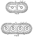
- Figures 5 and 6 Additional embodiments of the cell of this invention are shown in Figures 5 and 6.
- Figure 5 an oval type design is shown, and in Figure 6 a flat type design is shown.
- the electrode of Figure 5 is a somewhat flattened version of the electrode of Figures 3 and 4. Where the member 41 is still seen as connecting opposite interior walls of the electrode.
- circular chambers are shown, and the member 41 becomes less identifiable as a connecting member to interior walls, but it is still thick and has the ability to channel electrons from the far sides to the narrow interconnection 6 ⁇ which is deposited on the center 10% to 30% of the top air electrode structure.
Landscapes
- Chemical & Material Sciences (AREA)
- Chemical Kinetics & Catalysis (AREA)
- Electrochemistry (AREA)
- General Chemical & Material Sciences (AREA)
- Life Sciences & Earth Sciences (AREA)
- Engineering & Computer Science (AREA)
- Manufacturing & Machinery (AREA)
- Sustainable Development (AREA)
- Sustainable Energy (AREA)
- Fuel Cell (AREA)
- Inert Electrodes (AREA)
Claims (8)
- Pile annulaire de forme axialement allongée qui est destinée à un agencement de piles à combustible fonctionnant à haute température et qui comprend des électrodes poreuses intérieure et extérieure avec, entre elles, une couche d'électrolyte solide à base d'oxyde, ladite électrode extérieure et ladite couche d'électrolyte délimitant un intervalle recevant une interconnexion électro-conductrice déposée sur ladite électrode intérieure de manière à s'étendre sur la longueur axiale de cette dernière mais en étant espacée de ladite électrode extérieure suffisamment pour éviter une communication électrique directe avec cette dernière, caractérisée en ce que ladite électrode intérieure est auto-supportante et comprend une matière à base d'oxyde métallique définissant au moins deux chambres séparées d'un bout à l'autre de sa longueur axiale et permettant aux électrons se trouvant aux points de ladite électrode intérieure les plus éloignés de ladite interconnexion de se déplacer jusqu'à cette dernière à travers la matière à base d'oxyde métallique séparant les chambres.
- Pile selon la revendication 1, caractérisée en ce que l'électrode intérieure est plus épaisse que l'électrode extérieure.
- Pile selon les revendications 1 ou 2, caractérisée en ce que la matière à base d'oxyde métallique séparant les deux chambres se présente sous la forme d'un seul élément structural.
- Pile selon les revendications 1, 2 ou 3, caractérisée en ce que l'électrode intérieure est composée d'au moins un des produits parmi LaMnO₃, CaMnO₃, LaNiO₃, LaCoO₃ et LaCrO₃.
- Pile selon la revendication 4, caractérisée en ce que LaMnO₃ est dopé avec du strontium.
- Pile selon l'une quelconque des revendications 1 à 5, caractérisée en ce que la couche d'électrolyte est composée de zircone stabilisé par de l'oxyde d'yttrium et que l'électrode extérieure est composée de cermet à base de zircone-nickel ou de cermet à base de zircone-cobalt.
- Agencement de piles à combustible fonctionnant à haute température et à électrolyte à base d'oxyde solide, comprenant une pluralité de piles annulaires de forme axialement allongée telles que revendiquées dans l'une quelconque des revendications 1 à 5, caractérisé en ce que l'interconnexion présente sur une des piles annulaires est reliée électroniquement à une électrode extérieure d'une pile annulaire adjacente et en ce que chaque électrode intérieure est une électrode à air disposée de manière à être contactée par un oxydant et chaque électrode extérieure est une électrode à combustible disposée de manière à être contactée par un combustible.
- Agencement selon la revendication 7, caractérisé en ce que chacune des chambres séparées de l'électrode à air comporte un tube injecteur d'oxydant qui y est disposé.
Applications Claiming Priority (2)
| Application Number | Priority Date | Filing Date | Title |
|---|---|---|---|
| US3424587A | 1987-04-06 | 1987-04-06 | |
| US34245 | 1987-04-06 |
Publications (2)
| Publication Number | Publication Date |
|---|---|
| EP0285727A1 EP0285727A1 (fr) | 1988-10-12 |
| EP0285727B1 true EP0285727B1 (fr) | 1992-02-26 |
Family
ID=21875197
Family Applications (1)
| Application Number | Title | Priority Date | Filing Date |
|---|---|---|---|
| EP87310546A Expired - Lifetime EP0285727B1 (fr) | 1987-04-06 | 1987-11-30 | Electrodes autoportantes pour cellules à combustible à oxydes solides |
Country Status (5)
| Country | Link |
|---|---|
| EP (1) | EP0285727B1 (fr) |
| JP (1) | JP2700390B2 (fr) |
| CA (1) | CA1302486C (fr) |
| DE (1) | DE3776895D1 (fr) |
| NO (1) | NO875040L (fr) |
Cited By (1)
| Publication number | Priority date | Publication date | Assignee | Title |
|---|---|---|---|---|
| DE102004008231B4 (de) * | 2003-03-18 | 2009-05-07 | Ford Motor Co., Dearborn | Brennstoffzellenanordnung und Verfahren zur Herstellung einer Flachrohrbrennstoffzelle |
Families Citing this family (17)
| Publication number | Priority date | Publication date | Assignee | Title |
|---|---|---|---|---|
| US4751152A (en) * | 1987-04-06 | 1988-06-14 | Westinghouse Electric Corp. | High bulk self-supporting electrode with integral gas feed conduit for solid oxide fuel cells |
| US4874678A (en) * | 1987-12-10 | 1989-10-17 | Westinghouse Electric Corp. | Elongated solid electrolyte cell configurations and flexible connections therefor |
| DE3907485A1 (de) * | 1989-03-08 | 1990-09-20 | Asea Brown Boveri | Brennstoffzellenanordnung |
| JPH03274672A (ja) * | 1990-03-26 | 1991-12-05 | Ngk Insulators Ltd | 固体電解質型燃料電池 |
| JPH0697613B2 (ja) * | 1990-07-12 | 1994-11-30 | 日本碍子株式会社 | 固体電解質型燃料電池用空気電極材の製造方法 |
| US5292599A (en) * | 1991-09-27 | 1994-03-08 | Ngk Insulators, Ltd. | Cell units for solid oxide fuel cells and power generators using such cell units |
| DE19547700C2 (de) * | 1995-12-20 | 1998-09-17 | Forschungszentrum Juelich Gmbh | Elektrodensubstrat für eine Brennstoffzelle |
| DE19904203C2 (de) * | 1999-02-03 | 2001-05-10 | Forschungszentrum Juelich Gmbh | Brennstoffzelle nebst Herstellung in Batterieform |
| US6565632B1 (en) * | 2001-12-17 | 2003-05-20 | Praxair Technology, Inc. | Ion-transport membrane assembly incorporating internal support |
| JP4072049B2 (ja) * | 2002-12-25 | 2008-04-02 | 京セラ株式会社 | 燃料電池セル及び燃料電池 |
| CA2459612C (fr) | 2003-02-28 | 2010-04-13 | Kyocera Corporation | Pile a combustible |
| US7563533B2 (en) * | 2003-06-05 | 2009-07-21 | California Institute Of Technology | Ba-Sr-Co-Fe-O based perovskite mixed conducting materials as cathode materials for solid oxide fuel cells |
| US20070160886A1 (en) * | 2006-01-06 | 2007-07-12 | Siemens Power Generation, Inc. | Seamless solid oxide fuel cell |
| JP4776606B2 (ja) * | 2007-10-25 | 2011-09-21 | 京セラ株式会社 | 燃料電池 |
| JP2009283378A (ja) * | 2008-05-26 | 2009-12-03 | Hitachi Ltd | 固体酸化物形燃料電池管体、その成形方法およびその製造装置 |
| JP4986930B2 (ja) * | 2008-05-26 | 2012-07-25 | 京セラ株式会社 | 燃料電池およびその運転方法 |
| JP4881479B2 (ja) * | 2010-03-26 | 2012-02-22 | 日本碍子株式会社 | 燃料電池セル |
Family Cites Families (6)
| Publication number | Priority date | Publication date | Assignee | Title |
|---|---|---|---|---|
| US3228798A (en) * | 1962-04-12 | 1966-01-11 | Electric Storage Battery Co | Gas electrode |
| FR2304183A1 (fr) * | 1975-03-11 | 1976-10-08 | Accumulateurs Fixes | Pile a depolarisation par l'air |
| US3984303A (en) * | 1975-07-02 | 1976-10-05 | Diamond Shamrock Corporation | Membrane electrolytic cell with concentric electrodes |
| ZA814990B (en) * | 1980-12-22 | 1982-11-24 | Westinghouse Electric Corp | Fuel cell generator |
| AU545997B2 (en) * | 1980-12-22 | 1985-08-08 | Westinghouse Electric Corporation | High temp solid electrolyte fuel cell |
| US4476196A (en) * | 1983-10-12 | 1984-10-09 | The United States Of America As Represented By The United States Department Of Energy | Solid oxide fuel cell having monolithic cross flow core and manifolding |
-
1987
- 1987-11-23 CA CA000552474A patent/CA1302486C/fr not_active Expired - Lifetime
- 1987-11-30 EP EP87310546A patent/EP0285727B1/fr not_active Expired - Lifetime
- 1987-11-30 DE DE8787310546T patent/DE3776895D1/de not_active Expired - Lifetime
- 1987-12-03 NO NO875040A patent/NO875040L/no unknown
- 1987-12-04 JP JP62308482A patent/JP2700390B2/ja not_active Expired - Lifetime
Cited By (2)
| Publication number | Priority date | Publication date | Assignee | Title |
|---|---|---|---|---|
| DE102004008231B4 (de) * | 2003-03-18 | 2009-05-07 | Ford Motor Co., Dearborn | Brennstoffzellenanordnung und Verfahren zur Herstellung einer Flachrohrbrennstoffzelle |
| DE102004008231B9 (de) * | 2003-03-18 | 2009-09-10 | Ford Motor Co., Dearborn | Brennstoffzellenanordnung und Verfahren zur Herstellung einer Flachrohrbrennstoffzelle |
Also Published As
| Publication number | Publication date |
|---|---|
| JPS63261678A (ja) | 1988-10-28 |
| EP0285727A1 (fr) | 1988-10-12 |
| NO875040D0 (no) | 1987-12-03 |
| DE3776895D1 (de) | 1992-04-02 |
| CA1302486C (fr) | 1992-06-02 |
| JP2700390B2 (ja) | 1998-01-21 |
| NO875040L (no) | 1988-10-07 |
Similar Documents
| Publication | Publication Date | Title |
|---|---|---|
| US4888254A (en) | Low circumferential voltage gradient self supporting electrode for solid oxide fuel cells | |
| US4751152A (en) | High bulk self-supporting electrode with integral gas feed conduit for solid oxide fuel cells | |
| EP0320087B1 (fr) | Combinaison de cellules électrochimiques à forme allongée | |
| EP0285727B1 (fr) | Electrodes autoportantes pour cellules à combustible à oxydes solides | |
| US4791035A (en) | Cell and current collector felt arrangement for solid oxide electrochemical cell combinations | |
| US5273838A (en) | Double interconnection fuel cell array | |
| US3402230A (en) | Method of producing tubular fuel cell stack | |
| US4490444A (en) | High temperature solid electrolyte fuel cell configurations and interconnections | |
| EP0055016B1 (fr) | Arrangements de piles à combustible à électrolyte solide fonctionnant à haute température | |
| RU2007141681A (ru) | Конфигурации батарей трубчатых твердооксидных топливных элементов | |
| US5336569A (en) | Power generating equipment | |
| US5063122A (en) | Fuel cell assembly comprising permanently combined fuel cells | |
| US8389180B2 (en) | Electrolytic/fuel cell bundles and systems including a current collector in communication with an electrode thereof | |
| JP2004179071A (ja) | 燃料電池セル及び燃料電池 | |
| US8709674B2 (en) | Fuel cell support structure | |
| JP2599810B2 (ja) | 固体電解質燃料電池 | |
| JP6108724B2 (ja) | 電流案内が改善された燃料電池 | |
| EP0639866B1 (fr) | Electrode à air stable pour cellules à électrolyte solide d'oxydes et fonctionant à haute températures | |
| JP5300199B2 (ja) | 燃料電池 | |
| JP2816477B2 (ja) | 固体電解質燃料電池 | |
| JPH10106611A (ja) | 固体電解質型燃料電池 | |
| JP2777725B2 (ja) | 固体電解質型筒状燃料電池単体およびその製法 | |
| JPH077673B2 (ja) | 固体電解質燃料電池単体 | |
| EP0275364A1 (fr) | Pile à combustible à électrolyte solide et sa méthode de fabrication | |
| JP2000133292A (ja) | 燃料電池セルの出力測定装置 |
Legal Events
| Date | Code | Title | Description |
|---|---|---|---|
| PUAI | Public reference made under article 153(3) epc to a published international application that has entered the european phase |
Free format text: ORIGINAL CODE: 0009012 |
|
| AK | Designated contracting states |
Kind code of ref document: A1 Designated state(s): BE DE FR GB IT NL SE |
|
| 17P | Request for examination filed |
Effective date: 19890407 |
|
| 17Q | First examination report despatched |
Effective date: 19901004 |
|
| GRAA | (expected) grant |
Free format text: ORIGINAL CODE: 0009210 |
|
| AK | Designated contracting states |
Kind code of ref document: B1 Designated state(s): BE DE FR GB IT NL SE |
|
| ET | Fr: translation filed | ||
| REF | Corresponds to: |
Ref document number: 3776895 Country of ref document: DE Date of ref document: 19920402 |
|
| ITF | It: translation for a ep patent filed | ||
| PLBE | No opposition filed within time limit |
Free format text: ORIGINAL CODE: 0009261 |
|
| STAA | Information on the status of an ep patent application or granted ep patent |
Free format text: STATUS: NO OPPOSITION FILED WITHIN TIME LIMIT |
|
| 26N | No opposition filed | ||
| EAL | Se: european patent in force in sweden |
Ref document number: 87310546.4 |
|
| PGFP | Annual fee paid to national office [announced via postgrant information from national office to epo] |
Ref country code: SE Payment date: 19991118 Year of fee payment: 13 |
|
| PGFP | Annual fee paid to national office [announced via postgrant information from national office to epo] |
Ref country code: NL Payment date: 19991122 Year of fee payment: 13 |
|
| PGFP | Annual fee paid to national office [announced via postgrant information from national office to epo] |
Ref country code: BE Payment date: 19991123 Year of fee payment: 13 |
|
| PG25 | Lapsed in a contracting state [announced via postgrant information from national office to epo] |
Ref country code: BE Free format text: LAPSE BECAUSE OF NON-PAYMENT OF DUE FEES Effective date: 20001130 |
|
| PG25 | Lapsed in a contracting state [announced via postgrant information from national office to epo] |
Ref country code: SE Free format text: LAPSE BECAUSE OF NON-PAYMENT OF DUE FEES Effective date: 20001201 |
|
| BERE | Be: lapsed |
Owner name: WESTINGHOUSE ELECTRIC CORP. Effective date: 20001130 |
|
| PG25 | Lapsed in a contracting state [announced via postgrant information from national office to epo] |
Ref country code: NL Free format text: LAPSE BECAUSE OF NON-PAYMENT OF DUE FEES Effective date: 20010601 |
|
| NLV4 | Nl: lapsed or anulled due to non-payment of the annual fee |
Effective date: 20010601 |
|
| EUG | Se: european patent has lapsed |
Ref document number: 87310546.4 |
|
| REG | Reference to a national code |
Ref country code: GB Ref legal event code: IF02 |
|
| PGFP | Annual fee paid to national office [announced via postgrant information from national office to epo] |
Ref country code: GB Payment date: 20061109 Year of fee payment: 20 |
|
| PGFP | Annual fee paid to national office [announced via postgrant information from national office to epo] |
Ref country code: FR Payment date: 20061122 Year of fee payment: 20 |
|
| PGFP | Annual fee paid to national office [announced via postgrant information from national office to epo] |
Ref country code: IT Payment date: 20061130 Year of fee payment: 20 |
|
| PGFP | Annual fee paid to national office [announced via postgrant information from national office to epo] |
Ref country code: DE Payment date: 20070122 Year of fee payment: 20 |
|
| REG | Reference to a national code |
Ref country code: GB Ref legal event code: PE20 |
|
| PG25 | Lapsed in a contracting state [announced via postgrant information from national office to epo] |
Ref country code: GB Free format text: LAPSE BECAUSE OF EXPIRATION OF PROTECTION Effective date: 20071129 |