EP0285838A1 - Horloge autonome radiopilotée - Google Patents
Horloge autonome radiopilotée Download PDFInfo
- Publication number
- EP0285838A1 EP0285838A1 EP88103778A EP88103778A EP0285838A1 EP 0285838 A1 EP0285838 A1 EP 0285838A1 EP 88103778 A EP88103778 A EP 88103778A EP 88103778 A EP88103778 A EP 88103778A EP 0285838 A1 EP0285838 A1 EP 0285838A1
- Authority
- EP
- European Patent Office
- Prior art keywords
- radio clock
- clock according
- switched
- time
- energy
- Prior art date
- Legal status (The legal status is an assumption and is not a legal conclusion. Google has not performed a legal analysis and makes no representation as to the accuracy of the status listed.)
- Granted
Links
Images
Classifications
-
- G—PHYSICS
- G04—HOROLOGY
- G04C—ELECTROMECHANICAL CLOCKS OR WATCHES
- G04C10/00—Arrangements of electric power supplies in time-pieces
- G04C10/02—Arrangements of electric power supplies in time-pieces the power supply being a radioactive or photovoltaic source
-
- G—PHYSICS
- G04—HOROLOGY
- G04C—ELECTROMECHANICAL CLOCKS OR WATCHES
- G04C13/00—Driving mechanisms for clocks by primary clocks
- G04C13/02—Circuit arrangements; Electric clock installations
- G04C13/021—Circuit arrangements; Electric clock installations primary-secondary systems using transmission of singular pulses for driving directly secondary clocks step by step
- G04C13/026—Circuit arrangements; Electric clock installations primary-secondary systems using transmission of singular pulses for driving directly secondary clocks step by step by radio
Definitions
- the invention relates to an autonomous radio clock according to the preamble of claim 1.
- Such a clock is known from DE-OS 31 44 321 as a battery-operated radio-clock-quartz clock combination, in which functional parts, high power requirements in the interest of long battery life, are only switched on for a short time as required.
- the receiver for obtaining time information and the processor for processing the time information are referred to, which can be switched off after checking and, if necessary, correcting the time information currently displayed by means of the time display, because then the further time-keeping operation of the device over a predetermined period of time Time display from the quartz-stabilized circuit takes place.
- the invention has for its object to further increase the operating effort and the autonomous functional period of a generic clock.
- the functional parts switched off in order to reduce power in the dark can be switched on in accordance with the increase in the irradiance and / or the rise in the stored energy.
- a final connection can be provided until a switch-off has to take place again due to reduced radiation or reduced storage charge; or there is initially only a temporary connection, for example to carry out a pointer position correction based on received time information and then to use the energy supplied by the sun cell first until the storage state has reached a higher charge state before the final connection takes place again.
- the same effect can be achieved with less circuitry outlay if, for the dispensable (additional benefit) functional parts, regardless of the main memory for supplying the essential functional parts of the clock, a much smaller additional memory is provided. This is discharged very quickly when the solar cell radiation falls below a limit, so that the additional functions are then out of operation; while the charge reserve in the main memory is sufficient for a longer operation of the essential clock functions until possible as the solar cell radiation rises again (for example, when the next day breaks).
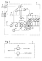
- a receiver 13 is fed, for example, via cable or a radio antenna (approximately in the form of a ferrite rod antenna coil) with absolute time information, which is supplied via a demodulator 14 to a so-called synchronization stage 15.
- This contains the decoded time information compared with the time information currently displayed on the time display 12 (shown in the drawing as comparison information 16); and in the event of a deviation, the time display 12 is readjusted, in the example shown, by correcting the angular position of the hands 17 by correspondingly controlling their stepper motors 18 via their driver circuits 19.
- the radio clock 11 can be equipped with so-called secondary uses, such as a calendar display 21, a decorative pendulum 22 (designed as a gravity pendulum or a rotary pendulum), an acoustic signal transmitter 23, moving figures and the like.
- secondary uses such as a calendar display 21, a decorative pendulum 22 (designed as a gravity pendulum or a rotary pendulum), an acoustic signal transmitter 23, moving figures and the like.
- All of these functional elements receive their operating energy from an electrical store 25, which can be a physical (capacitor) or chemical (accumulator) charge store.
- the storage 25 is recharged photovoltaically from at least one solar cell 26, which converts incident radiation energy 27 into electrical energy.
- the drive is switched over by the synchronizing stage 15 from the receiver demodulator 14 for further time-keeping operation from a quartz-stabilized circuit 28.
- the receiver 13 is then used its demodulator 14 switched off - and only switched on again temporarily after a period of time specified in terms of circuitry or after the occurrence of an operational malfunction, in order to control the presentation on the time display 12 and, if necessary, to correct it.
- the power requirement for operating only the time display 12 from the time-keeping circuit 28 is very low.
- the sun cell 26 with its memory 25 must be greatly oversized in order to move the ornamental pendulum 22 and to feed the calendar display 21, the acoustic signal generator 23 and / or the receiver 13 with demodulator 14 from time to time.
- the corresponding dimensions of the memory 25 and the sun cell 26 are included in their size, that is to say in the space required within the radio clock 11, which greatly limits the possibilities for realizing a small-sized radio clock 11 and the freedom of movement in its design.
- a power reserve is therefore provided, the minimum value of which is only slightly above the minimum power requirement for the operation of the radio clock 11.
- the memory 25 is loaded to such an extent that the power reserve is sufficient not only for the operation of the receiver 13 with the demodulator 14, but also for the additional benefits (21, 22, 23 ).
- the power reserve in the memory 25 drops rapidly and possibly below the level required for operation, at least those additional benefits, possibly even the time display 12.
- the most dispensable benefits are those whose interruption to operations is not noticeable. These are in particular all decorative additional benefits such as an ornamental pendulum 22, which can no longer be perceived anyway in the case of low ambient brightness, that is to say with weak radiation energy 27. Secondly, this includes additional benefits such as a calendar display 21, to which attention is paid only occasionally and therefore not exactly in the dark. But also an acoustic signal generator 23 is such a dispensable additional benefit, since it would only disturb the night's rest, i.e. it can be switched off easily in the dark - which is easier to implement with the brightness-controlled switch 29 than with a separate decoding circuit for the exact time-dependent nightly switching off of an acoustic signal Signal generator 23.
- a separate photo element 30 can be provided for the function of the relief switch 29, which is dependent on the ambient brightness, and is acted upon by the same radiation energy 27 as the sun cell 26. Instead, however (also taken into account in the drawing in dashed lines), the sun cell 26 itself can also take over the function of the photoelement 30, that is to say apart from the memory 25 Control at least one threshold value stage 31 to open the switches 29 when the ambient brightness has dropped significantly.
- the drawing also takes into account the expedient possibility of querying the available operating energy, that is to say the state of charge of the memory 25, as an additional criterion for switching off dispensable additional benefits, via a voltage detector 32, which also functions as a threshold value stage.
- an OR gate 33 of the brightness threshold level 31 or of Memory voltage detector 32 switched through to open the switch 29 and thus switch off the dispensable additional benefits (21, 22, 23 7) for relieving the operating voltage source from the memory 25, that is to say the remaining runtime of the radio clock 11 with its time display 12 and the temporarily switched on Extend receiver 13 otherwise.
- the switching off of dispensable additional benefits can be done as a flat rate or staggered depending on the available brightness and storage conditions.
- further functions of the radio clock 11 that are already less indispensable can be switched off when the power reserve in the memory 25 has dropped to an extremely low level in the dark, for example the brightness threshold value stage 31 and the memory voltage detector 32 via an AND gate 34 open another switch 29.
- the periodic connection of the receiver 13 with its demodulator 14, and therefore also the function of the synchronization stage 15 for influencing the time display 12, are thereby put out of operation.
- This also removes the feed into the driver circuit 19.2 for the movement of the minute hand 17.2.
- the - already almost discharged - memory 25 now only needs to feed the extremely low-power time-keeping circuit 28 for the timely advancement of the hour hand 17.1. Since its stepper motor 18.1 receives a drive pulse only at a correspondingly large time interval, the load on the memory 25 is reduced to the power requirement of the time-keeping circuit 28, which in modern integrated circuits is hardly larger than the self-discharge energy loss in question here is.
- a directional signal 35 symbolically indicates in the drawing that it may be expedient to turn the minute hand 17.2 into a defined position before the minute hand stepping motor 18.2 is switched off, in order to continue misinterpretations (with regard to the angular position of the minute hand 17.2 which is then stationary) to avoid timely driven hour hands 17.1).
- a reference position can be the position of a digit of the time display 12, such as the digit "6"; or any angular position that bears a corresponding information mark on the dial. If the observer of the radio-controlled clock 11 thus notices the minute hand 17.1 in such a marked position, he will observe whether the minute hand 17.1 remains in this position. If this is the case, then only the position of the hour hand 17.2 shows time information because the minute hand 17.1, just like before, all the additional benefits have been switched off due to a reduced power reserve in a dark environment.
- the switch-off via the AND gate 34 is first withdrawn, i.e. the minute hand stepper motor 18.2 is fed again and the receiver 13 together with the demodulator 14 and the complete one Function of synchronization stage 15 switched on.
- the first decoded time information is then immediately available for the correction of the pointer position on the time display 12, so that the complete time information is then presented again.
- the switching through of the OR gate 33 and thus the switching off of the additional benefits is also withdrawn, so that afterwards all the functions of the radio clock 11 are in operation again.
- a greatly reduced circuit complexity for the same effect results if the switch 29 in the feed line (according to FIG. 1) and the switch control are dispensed with for the functional parts to be switched off and instead according to FIG. 2 except for the main memory 25 a smaller capacity, on the other hand, having a smaller capacity and additional memory 25 ⁇ , which is loaded independently of the main memory 25 from the sun cell 26, is provided.
- the additional memory 25 ⁇ is used to supply the less functionally important additional benefits of the radio clock 11, such as the drive of a decorative pendulum 22.
- the charge of the additional memory 25 ⁇ is soon exhausted and the corresponding additional benefit is therefore inoperative set.
- the larger main memory 25, which is not burdened by the additional benefit, on the other hand has an energy reserve which keeps the important functional parts of the clock 11 fed from it in operation even over a longer period of time.
- sun cell 26 is provided above to simplify the illustration as an energy supplier
- another radiation-operated generator such as a thermal generator for charging the memories 25, 25, for operating the radio clock 11 can also be provided.
Landscapes
- Physics & Mathematics (AREA)
- General Physics & Mathematics (AREA)
- Engineering & Computer Science (AREA)
- Power Engineering (AREA)
- Electromechanical Clocks (AREA)
- Electric Clocks (AREA)
Priority Applications (1)
| Application Number | Priority Date | Filing Date | Title |
|---|---|---|---|
| AT88103778T ATE68273T1 (de) | 1987-03-11 | 1988-03-10 | Autonome funkuhr. |
Applications Claiming Priority (2)
| Application Number | Priority Date | Filing Date | Title |
|---|---|---|---|
| DE3707728 | 1987-03-11 | ||
| DE19873707728 DE3707728A1 (de) | 1987-03-11 | 1987-03-11 | Autonome funkuhr |
Publications (2)
| Publication Number | Publication Date |
|---|---|
| EP0285838A1 true EP0285838A1 (fr) | 1988-10-12 |
| EP0285838B1 EP0285838B1 (fr) | 1991-10-09 |
Family
ID=6322733
Family Applications (1)
| Application Number | Title | Priority Date | Filing Date |
|---|---|---|---|
| EP88103778A Expired - Lifetime EP0285838B1 (fr) | 1987-03-11 | 1988-03-10 | Horloge autonome radiopilotée |
Country Status (3)
| Country | Link |
|---|---|
| EP (1) | EP0285838B1 (fr) |
| AT (1) | ATE68273T1 (fr) |
| DE (3) | DE3707728A1 (fr) |
Cited By (5)
| Publication number | Priority date | Publication date | Assignee | Title |
|---|---|---|---|---|
| WO1998033098A1 (fr) * | 1997-01-23 | 1998-07-30 | Eta Sa Fabriques D'ebauches | Montre comportant des moyens de detection et de sauvegarde en cas d'insuffisance de la source d'alimentation |
| EP0886197A1 (fr) * | 1997-06-17 | 1998-12-23 | Seiko Epson Corporation | Circuit de détection de la génération de puissance, dispositif semiconducteur, dispositif électronique, pièce d'horlogerie, méthode de détection de la génération de puissance, et méthode de contrÔle de la consomation d'énergie |
| EP0809160A4 (fr) * | 1995-12-06 | 1999-03-10 | Citizen Watch Co Ltd | Horloge radiocalibree |
| EP0909996A3 (fr) * | 1997-10-17 | 2002-12-18 | Junghans Uhren GmbH | Montre radio alimentée par énergie solaire |
| EP1669818A4 (fr) * | 2003-09-30 | 2008-03-05 | Seiko Epson Corp | Horloge commandee par radio, dispositif electronique, procede de commande d'horloge commandee par radio, et programme de commande de reception d'horloge commandee par radio |
Families Citing this family (3)
| Publication number | Priority date | Publication date | Assignee | Title |
|---|---|---|---|---|
| DE4002723C2 (de) * | 1990-01-31 | 2003-06-26 | Junghans Uhren Gmbh | Autonome Funkuhr |
| DE4220452A1 (de) * | 1992-06-23 | 1994-01-13 | Senden Uhrenfab Gmbh | Batteriebetriebene Groß- oder Kleinuhr mit Prüfeinrichtung für den Ladezustand der Batterie |
| DE20019177U1 (de) | 2000-09-27 | 2001-01-25 | Derksen, Joachim Max, 45889 Gelsenkirchen | Uhr und Projektionssystem |
Citations (1)
| Publication number | Priority date | Publication date | Assignee | Title |
|---|---|---|---|---|
| EP0208986A1 (fr) * | 1985-07-06 | 1987-01-21 | Junghans Uhren Gmbh | Appareil miniature électrique alimenté par cellules solaires, en particulier montre solaire |
Family Cites Families (1)
| Publication number | Priority date | Publication date | Assignee | Title |
|---|---|---|---|---|
| DE3600515C1 (de) * | 1986-01-10 | 1993-05-13 | Fraunhofer Ges Forschung | Elektronische Uhr |
-
1987
- 1987-03-11 DE DE19873707728 patent/DE3707728A1/de not_active Withdrawn
- 1987-03-11 DE DE8718063U patent/DE8718063U1/de not_active Expired - Lifetime
-
1988
- 1988-03-10 AT AT88103778T patent/ATE68273T1/de not_active IP Right Cessation
- 1988-03-10 DE DE8888103778T patent/DE3865341D1/de not_active Expired - Fee Related
- 1988-03-10 EP EP88103778A patent/EP0285838B1/fr not_active Expired - Lifetime
Patent Citations (1)
| Publication number | Priority date | Publication date | Assignee | Title |
|---|---|---|---|---|
| EP0208986A1 (fr) * | 1985-07-06 | 1987-01-21 | Junghans Uhren Gmbh | Appareil miniature électrique alimenté par cellules solaires, en particulier montre solaire |
Non-Patent Citations (3)
| Title |
|---|
| ELECTRONICS, Band 59, 30. Oktober 1986, Seiten 38-44, New York, US; J. GOSCH: "In 1,500 centuries, this clock will lose 1 second" * |
| PATENT ABSTRACTS OF JAPAN, Band 10, Nr. 250 (P-491)[2306], 28. August 1986; & JP-A-61 077 788 (CITIZEN WATCH CO., LTD) 21-04-1986 * |
| PATENT ABSTRACTS OF JAPAN, Band 7, Nr. 113 (P-197)[1258], 18. Mai 1983; & JP-A-58 033 178 (SUWA SEIKOSHA K.K.) 26-02-1983 * |
Cited By (7)
| Publication number | Priority date | Publication date | Assignee | Title |
|---|---|---|---|---|
| EP0809160A4 (fr) * | 1995-12-06 | 1999-03-10 | Citizen Watch Co Ltd | Horloge radiocalibree |
| WO1998033098A1 (fr) * | 1997-01-23 | 1998-07-30 | Eta Sa Fabriques D'ebauches | Montre comportant des moyens de detection et de sauvegarde en cas d'insuffisance de la source d'alimentation |
| US6144622A (en) * | 1997-01-23 | 2000-11-07 | Eta Sa Fabriques D'ebauches | Watch comprising sensing and saving means in case of insufficiency of supply source |
| EP0886197A1 (fr) * | 1997-06-17 | 1998-12-23 | Seiko Epson Corporation | Circuit de détection de la génération de puissance, dispositif semiconducteur, dispositif électronique, pièce d'horlogerie, méthode de détection de la génération de puissance, et méthode de contrÔle de la consomation d'énergie |
| US6140863A (en) * | 1997-06-17 | 2000-10-31 | Seiko Epson Corporation | Power-generation detection circuit for use in an electronic device and power-generation detection method and power consumption control method for use in connection therewith |
| EP0909996A3 (fr) * | 1997-10-17 | 2002-12-18 | Junghans Uhren GmbH | Montre radio alimentée par énergie solaire |
| EP1669818A4 (fr) * | 2003-09-30 | 2008-03-05 | Seiko Epson Corp | Horloge commandee par radio, dispositif electronique, procede de commande d'horloge commandee par radio, et programme de commande de reception d'horloge commandee par radio |
Also Published As
| Publication number | Publication date |
|---|---|
| EP0285838B1 (fr) | 1991-10-09 |
| DE3707728A1 (de) | 1988-09-22 |
| ATE68273T1 (de) | 1991-10-15 |
| DE3865341D1 (de) | 1991-11-14 |
| DE8718063U1 (de) | 1993-03-25 |
Similar Documents
| Publication | Publication Date | Title |
|---|---|---|
| DE3524290C2 (fr) | ||
| DE60131310T2 (de) | Zeithaltendes Gerät und Kontrollverfahren dafür | |
| DE68920746T2 (de) | Lichtgespeistes elektronisches energieverwaltungssystem. | |
| EP1004860A1 (fr) | Balance electronique avec foncionnement en mode veille | |
| DE69621392T2 (de) | Elektronische Uhr | |
| DE69616758T2 (de) | Funkgeeichte uhr | |
| EP0285838A1 (fr) | Horloge autonome radiopilotée | |
| EP0228635B2 (fr) | Montre électronique | |
| DE3903706C2 (fr) | ||
| DE2004076A1 (de) | Elektronische Uhr geringen Leistungsbedarfes | |
| EP0439725A2 (fr) | Horloge radio-pilotée autonome | |
| DE69702230T2 (de) | Elektronische uhr mit elektrizitäts-ladefunktion | |
| DE69827362T2 (de) | Uhr mit detektions- und sparvorrichtungen im falle von nicht ausreichender energieversorgung | |
| US4901295A (en) | Device comprising a solar cell for winding a barrel spring | |
| DE2442394B2 (de) | Vollelektronische uhr | |
| CH524973A (de) | Verfahren zum Einführen und Aufziehen von Reissverschlussschiebern auf fortlaufende, gekuppelte Reissverschlussstreifen | |
| EP0608734B1 (fr) | Montre bracelet | |
| DE60312536T2 (de) | Elektromechanische Uhr, die mit einer Gangreserveanzeige ausgerüstet ist | |
| EP0909996A2 (fr) | Montre radio alimentée par énergie solaire | |
| DE3702993A1 (de) | Quarzuhr | |
| DE1673798B2 (de) | Elektrischer zeitmesser mit einem durch eine solar oder photozelle aufladbaren akkumulator | |
| DE69607499T2 (de) | Uhr mit durch Funksignale kontrolierter Korrekturfunktion | |
| DE4424337C2 (de) | Verfahren zum Stellen der Zeiger einer elektrischen Uhr und entsprechende Uhr | |
| EP1759249B1 (fr) | Procede et dispositif pour regler l'affichage de la date sur une montre, notamment une montre radio, apres changement de piles | |
| DE1673798C (de) | Elektrischer Zeitmesser mit einem durch eine Solar- oder Photozelle aufladbaren Akkumulator |
Legal Events
| Date | Code | Title | Description |
|---|---|---|---|
| PUAI | Public reference made under article 153(3) epc to a published international application that has entered the european phase |
Free format text: ORIGINAL CODE: 0009012 |
|
| AK | Designated contracting states |
Kind code of ref document: A1 Designated state(s): AT BE CH DE FR GB IT LI NL SE |
|
| 17P | Request for examination filed |
Effective date: 19880927 |
|
| 17Q | First examination report despatched |
Effective date: 19900322 |
|
| GRAA | (expected) grant |
Free format text: ORIGINAL CODE: 0009210 |
|
| AK | Designated contracting states |
Kind code of ref document: B1 Designated state(s): AT BE CH DE FR GB IT LI NL SE |
|
| REF | Corresponds to: |
Ref document number: 68273 Country of ref document: AT Date of ref document: 19911015 Kind code of ref document: T |
|
| REF | Corresponds to: |
Ref document number: 3865341 Country of ref document: DE Date of ref document: 19911114 |
|
| ITF | It: translation for a ep patent filed | ||
| ET | Fr: translation filed | ||
| GBT | Gb: translation of ep patent filed (gb section 77(6)(a)/1977) | ||
| PLBE | No opposition filed within time limit |
Free format text: ORIGINAL CODE: 0009261 |
|
| STAA | Information on the status of an ep patent application or granted ep patent |
Free format text: STATUS: NO OPPOSITION FILED WITHIN TIME LIMIT |
|
| 26N | No opposition filed | ||
| PGFP | Annual fee paid to national office [announced via postgrant information from national office to epo] |
Ref country code: BE Payment date: 19950116 Year of fee payment: 8 |
|
| EAL | Se: european patent in force in sweden |
Ref document number: 88103778.2 |
|
| PGFP | Annual fee paid to national office [announced via postgrant information from national office to epo] |
Ref country code: AT Payment date: 19950227 Year of fee payment: 8 |
|
| PGFP | Annual fee paid to national office [announced via postgrant information from national office to epo] |
Ref country code: SE Payment date: 19950330 Year of fee payment: 8 |
|
| PGFP | Annual fee paid to national office [announced via postgrant information from national office to epo] |
Ref country code: NL Payment date: 19950331 Year of fee payment: 8 |
|
| PGFP | Annual fee paid to national office [announced via postgrant information from national office to epo] |
Ref country code: GB Payment date: 19960304 Year of fee payment: 9 |
|
| PG25 | Lapsed in a contracting state [announced via postgrant information from national office to epo] |
Ref country code: AT Effective date: 19960310 |
|
| PG25 | Lapsed in a contracting state [announced via postgrant information from national office to epo] |
Ref country code: SE Effective date: 19960311 |
|
| PG25 | Lapsed in a contracting state [announced via postgrant information from national office to epo] |
Ref country code: BE Effective date: 19960331 |
|
| BERE | Be: lapsed |
Owner name: JUNGHANS UHREN G.M.B.H. Effective date: 19960331 |
|
| PG25 | Lapsed in a contracting state [announced via postgrant information from national office to epo] |
Ref country code: NL Effective date: 19961001 |
|
| NLV4 | Nl: lapsed or anulled due to non-payment of the annual fee |
Effective date: 19961001 |
|
| EUG | Se: european patent has lapsed |
Ref document number: 88103778.2 |
|
| PGFP | Annual fee paid to national office [announced via postgrant information from national office to epo] |
Ref country code: FR Payment date: 19970127 Year of fee payment: 10 |
|
| PG25 | Lapsed in a contracting state [announced via postgrant information from national office to epo] |
Ref country code: GB Effective date: 19970310 |
|
| GBPC | Gb: european patent ceased through non-payment of renewal fee |
Effective date: 19970310 |
|
| PG25 | Lapsed in a contracting state [announced via postgrant information from national office to epo] |
Ref country code: FR Free format text: THE PATENT HAS BEEN ANNULLED BY A DECISION OF A NATIONAL AUTHORITY Effective date: 19980331 |
|
| REG | Reference to a national code |
Ref country code: FR Ref legal event code: ST |
|
| PGFP | Annual fee paid to national office [announced via postgrant information from national office to epo] |
Ref country code: CH Payment date: 19990218 Year of fee payment: 12 |
|
| PGFP | Annual fee paid to national office [announced via postgrant information from national office to epo] |
Ref country code: DE Payment date: 19990526 Year of fee payment: 12 |
|
| PG25 | Lapsed in a contracting state [announced via postgrant information from national office to epo] |
Ref country code: LI Free format text: LAPSE BECAUSE OF NON-PAYMENT OF DUE FEES Effective date: 20000331 Ref country code: CH Free format text: LAPSE BECAUSE OF NON-PAYMENT OF DUE FEES Effective date: 20000331 |
|
| REG | Reference to a national code |
Ref country code: CH Ref legal event code: PL |
|
| PG25 | Lapsed in a contracting state [announced via postgrant information from national office to epo] |
Ref country code: DE Free format text: LAPSE BECAUSE OF NON-PAYMENT OF DUE FEES Effective date: 20010103 |
|
| PG25 | Lapsed in a contracting state [announced via postgrant information from national office to epo] |
Ref country code: IT Free format text: LAPSE BECAUSE OF NON-PAYMENT OF DUE FEES;WARNING: LAPSES OF ITALIAN PATENTS WITH EFFECTIVE DATE BEFORE 2007 MAY HAVE OCCURRED AT ANY TIME BEFORE 2007. THE CORRECT EFFECTIVE DATE MAY BE DIFFERENT FROM THE ONE RECORDED. Effective date: 20050310 |