EP0285894B1 - Appareil de prise de vues - Google Patents
Appareil de prise de vues Download PDFInfo
- Publication number
- EP0285894B1 EP0285894B1 EP88104506A EP88104506A EP0285894B1 EP 0285894 B1 EP0285894 B1 EP 0285894B1 EP 88104506 A EP88104506 A EP 88104506A EP 88104506 A EP88104506 A EP 88104506A EP 0285894 B1 EP0285894 B1 EP 0285894B1
- Authority
- EP
- European Patent Office
- Prior art keywords
- signals
- pixels
- read
- sequence
- lines
- Prior art date
- Legal status (The legal status is an assumption and is not a legal conclusion. Google has not performed a legal analysis and makes no representation as to the accuracy of the status listed.)
- Expired - Lifetime
Links
Images


Classifications
-
- H—ELECTRICITY
- H04—ELECTRIC COMMUNICATION TECHNIQUE
- H04N—PICTORIAL COMMUNICATION, e.g. TELEVISION
- H04N25/00—Circuitry of solid-state image sensors [SSIS]; Control thereof
- H04N25/70—SSIS architectures; Circuits associated therewith
- H04N25/76—Addressed sensors, e.g. MOS or CMOS sensors
-
- H—ELECTRICITY
- H04—ELECTRIC COMMUNICATION TECHNIQUE
- H04N—PICTORIAL COMMUNICATION, e.g. TELEVISION
- H04N25/00—Circuitry of solid-state image sensors [SSIS]; Control thereof
- H04N25/40—Extracting pixel data from image sensors by controlling scanning circuits, e.g. by modifying the number of pixels sampled or to be sampled
- H04N25/44—Extracting pixel data from image sensors by controlling scanning circuits, e.g. by modifying the number of pixels sampled or to be sampled by partially reading an SSIS array
- H04N25/443—Extracting pixel data from image sensors by controlling scanning circuits, e.g. by modifying the number of pixels sampled or to be sampled by partially reading an SSIS array by reading pixels from selected two-dimensional [2D] regions of the array, e.g. for windowing or digital zooming
Definitions
- the present invention relates to an imaging apparatus having a function for reading an image in a magnified size, being referred to as "zooming" function hereinafter, and a method for operating the same.
- the invention relates to an imaging apparatus comprising a plurality of pixels arranged in lines and columns, and control means for selectively switching the reading operation mode between a first mode, in which signals on said pixels are sequentially read in a first sequence and at a first speed, and a second mode, in which signals on a selected portion of the area of said pixels are sequentially read in a second sequence different from said first sequence and at a second speed different from said first speed.
- Patent application document DE 29 13 116 A1 discloses a method for converting the number of scanning lines from 525 to 625 by reading every third line twice.
- FIG. 9A is an illustration of an image formed on an imaging device, including a portion to be zoomed out
- Figs. 9B and 9C are timing charts showing, respectively, the manner in which vertical scan is conducted during the operation of an imaging apparatus in a zoom-out reading mode and the manner in which horizontal scan is conducted along horizontal lines which include the image portion to be zoomed out.
- an image of an object is formed on a two-dimensional imaging device 101. It is assumed that only a portion 102 of the image is to be displayed on a greater scale, while the other portions of the image are to be neglected. To this end, it is necessary that the signals from the portion of the imaging device 101 corresponding to the image portion 102 are read in the effective television period, while signals from the other portions are read during the horizontal and vertical blanking periods.
- the signals from the scanning lines 1 to (a-1), corresponding to an unnecessary portion of the image, are shifted at a high speed in a period t1 within the vertical blanking period VBLK.
- the signals from the scanning lines a to b , covering the portion 102 of the image, are shifted at a low speed in a period t2 which is the vertical effective period.
- each of the horizontal lines a to b is horizontally scanned in a manner shown in Fig. 9C.
- the manner of the horizontal scan along each of the horizontal scanning lines a to b is conducted in a manner which will be explained hereinunder with reference to Fig. 9C. Namely, the signals from the unnecessary portion which is to the left of the image portion 102 to be zoomed out are shifted at a high speed in a period t21 within the first horizontal blanking period. Then, the signals from the portion corresponding to the image portion 102 are shifted at a low speed in the effective period t22. Finally, the signals corresponding to the unnecessary portion which is to the right of the image portion 102 are transferred at a high speed within the next horizontal blanking period t23.
- the image portion 102 includes n/2 horizontal scanning lines. If this image portion 102 is displayed with the magnification 2 on, for example, a television screen, therefore, the quality of the image is impaired due to the presence of noise in the form of horizontal stripes.
- known imaging apparatus usually employ memory means or delay means which store or delay the zoomed-out read signals such that the signal for each line is used twice, so as to provide n pieces of scanning lines on the display, thereby to avoid degradation of the quality of the display image.
- This known imaging apparatus requires a large and complicated circuit to perform this function and, hence, the production cost is raised due to the use of the memory or delay means which is intended for the multiple use described above of the image signals.
- the same problem is encountered also with an apparatus of the type which employs interpolation between a pair of distant line signals or prediction of a next line signal from the preceding line signal.
- the circuit is further complicated when the signals are read through a plurality of signal lines.
- This object is achieved by providing an imaging apparatus which comprises means by which pairs of adjacent lines are successively read in vertical direction in each field, wherein said pairs of adjacent lines read from an odd-number field and from an even-number field respectively overlap with each other in one line.
- this object is achieved by using a method comprising the step that pairs of adjacent lines in vertical direction are successively read in each field, wherein said pairs of adjacent lines read from an odd-number field and from an even-number field respectively overlap with each other in one line.
- a zoomed-out display can be realized without additional memory or delay means being necessary.
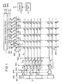
- Fig. 1 is a schematic circuit diagram of an embodiment of the imaging apparatus in accordance with the present invention.
- the imaging apparatus has an imaging device having a multiplicity of photo-sensors 1 which are arranged in the form of a matrix constituted by m rows and n columns.
- the photo-sensor 1 may be of any type, such as destructive reading type, non-destructive reading type, MOS type, electrostatic induction type, base accumulation type, and so forth.
- the photo-sensors of each row are connected to a horizontal line HL.
- a plurality of rows of photo-sensors 1 are connected to corresponding horizontal lines HL, each of which is adapted to receive driving pulses ⁇ R1 and ⁇ R2 through transistors Q r1 and Q r2 respectively, whereby the lines of photo-sensors are driven independently for the purpose of reading of signals and resetting.
- the gates of the gate electrodes of the transistors Q r1 and Q r2 of each two adjacent horizontal lines are commonly connected and the common connections of these gate electrodes are connected to output terminals of a vertical scanning circuit 2 through transistors Q e and Q o which appear alternately for the successive horizontal lines HL.
- the gate electrodes of the transistors Q e and Q o receive field selection pulses ⁇ FE and ⁇ FO , respectively.
- the transistors Q e , Q o and the transistors Q r1 , Q r2 in combination constitute an interlace circuit.
- the vertical scanning circuit 2 starts the scanning operation in response to a start pulse ⁇ VS and successively outputs vertical scanning pulses in synchronization with the pulses ⁇ V1 and ⁇ V2.
- the columns of the photo-sensors 1 are connected to corresponding vertical lines VL, each of which is connected to temporary storage capacitors C1 and C2 through shifting transistors Q t1 and Q t2 .
- the capacitors C1 and C2 are connected to signal lines S1 and S2, through scanning transistors QS1 and QS2.
- the gate electrodes of the scanning transistors Q s1 and Q s2 of each pair are commonly connected and the common connections of the successive pairs of scanning transistors Q s1 and Q s2 receive scanning pulses from the horizontal scanning circuit 3. More specifically, the horizontal scanning circuit 3 starts the scanning operation in response to a start pulse ⁇ HS and outputs scanning pulses in synchronization with pulses ⁇ H1 and ⁇ H2.
- Each vertical line VL is grounded through a transistor Q vc which receives at its gate electrode a pulse ⁇ VC.
- the pulses ⁇ mentioned above are supplied from a driver 4 which is controlled by a control unit 5.
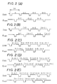
- the horizontal pixel lines covering the image portion 102 are scanned twice in a non-interlaced manner. More specifically, the scanning lines a , a+1 , a+2 , ...., b-1 , b are sequentially read from an odd-number field of the display, and the same lines a to b are read again for the even-number field of the display.
- a second type of operation illustrated in Fig. 2B, the reading is conducted by means of a photo-sensor which is capable of enabling a signal to be read in a non-destructive manner.
- the signal of the photo-sensor is not destroyed by the reading operation, and the pixel signals of each line are successively read twice.
- scanning lines are read as a , (a) , a+2 , (a+2) , ... for the odd-number field of the display, where (a) , (a+2) , etc, each represents the second reading of the scanning line a , a+2 , etc.
- scanning lines are read as a+1 , (a+1) , a+3 , (a+3) ,...., as will be seen from Fig. 2B.
- Fig. 2C shows the ordinary reading operation in a double-line reading system, as an example of the above-mentioned multiple-line reading system.
- pairs of scanning lines 1,2; 3,4; ...; a , a+1 ;... are read sequentially for the odd-number field, while pairs of scanning lines 2,3; 4,5;... ;a+1 , a+2 ;... are read for the even-number field.
- Fig. 2D shows a third type of reading operation with the circuit shown in Fig. 1.
- the double-line reading system is used with both of the pair of scanning lines read in a non-destructive manner.
- scanning lines are read as a , a+1 ; ( a , a+1 ); a+2 , a+3 ; ( a+2 , a+3 )..., for the odd-number field, while the scanning lines are read as a+2 , a+3 ; ( a+2 , a+3 );... for the even number field.
- Fig. 2E shows a fourth type of reading operation in which the double-line reading system is used with only one of each pair of scanning lines read in the non-destructive manner.
- the scanning lines are read as a ; a+1 ; ( a+1 ), a+2 ;... for the odd-number field, whereas, scanning lines are read as ( a+1 ), a+2 ; ( a+2 ), a+3 ;... for the even-number field.
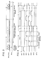
- Fig. 3 is a schematic timing chart illustrating the operation of the vertical scanning circuit driven by the driver 4 in the zoom-out reading mode.
- the vertical scanning circuit 2 starts to operate in response to a start pulse ⁇ VS and sequentially outputs vertical scanning pulses in accordance with the pulses ⁇ V1 and ⁇ V2.
- Fig. 4 is a timing chart illustrating a practical example of the first type of reading operation described before in connection with Fig. 2A.
- the scanning is conducted in a non-interlaced manner without using the pulses ⁇ R2.
- the photo-sensor need not be of non-destructive type.
- the pulse ⁇ V1 and the pulse ⁇ FE for field selection are set high to enable the vertical scanning circuit 2 to output scanning pulses, thereby to turn on the transistors Q e and Q r1 corresponding to the beginning scanning lines a and a+1 of the image portion 102 to be zoomed out.
- the transistors Q r2 are not turned on because in this case the pulses ⁇ R2 are not used.
- the pulses ⁇ T1 and ⁇ VC are set high so as to turn on the transistors Q t1 and Q vc , thereby clearing the vertical lines VL and the temporary storage capacitors C1.
- the transistors Q vc are turned off, and the pulse ⁇ R1 is set high, thereby driving the rows of photo-sensors constituting the pixels of the horizontal scanning line a .
- signals on the photo-sensors or pixels on the scanning line a are read and stored in the capacitors C1 through the transistors Q t1 .
- the transistors Q t1 are turned off, while the transistors Q vc are turned on so as to ground the vertical lines VL. Then, the pulse ⁇ R1 is set high high so as to reset the photo-sensors of the scanning line a .
- the signals corresponding to the scanning line a stored in the capacitors C1 are scanned by the horizontal scanning circuit 3 and are sequentially shifted to the signal line S1 through the transistors Q s1 .
- the shifting of the signals is conducted in such a manner that, as explained before in connection with Fig. 9C, the signals from the unnecessary portions of the image are shifted at a high speed in the periods t21 and t23 within the horizontal blanking periods, whereas the signals corresponding to the image portion 102 to be zoomed out are shifted in the horizontal effective period t22.
- the field selection pulse ⁇ FE falls and, instead, the field selection pulse ⁇ FO rises, when the shifting of all the signals from the scanning line a is finished.
- the transistors Q o are turned on so that the transistor Q r1 corresponding to the scanning line a+1 is turned on. In this case, therefore, the clearing of the capacitors C1, reading of signals and the resetting of the photo-sensors are conducted in connection with the scanning line a+1 .
- the pulses ⁇ V1 and ⁇ V2 are set low and high, respectively, so that the vertical scanning circuit 2 shifts the position of output of the scanning pulse to the next stage and outputs the scanning pulse for the next stage when the next pulse ⁇ V1 is set high.
- the scanning is executed in non-interlaced manner so that the signals from the scanning lines a , a+1 , a+2 ,... are sequentially read for the even number field, while the same lines a+1 , a+2 ,... are read once again for the even number field.
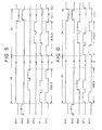
- Fig. 5 is a timing chart illustrating another practical example of the first type of operation explained before in connection with Fig. 2A.
- the field selection pulse ⁇ FE is maintained at high level so that only the transistors Q e are turned on, and the non-interlaced scanning is executed only by means of the pulses ⁇ R1 and ⁇ R2.
- the pulse ⁇ V1 is set high so that the transistors Q r1 and Q r2 corresponding to the scanning lines a and a+1 are turned on.
- the capacitors C1 are cleared and the signals from the photo-sensors on the scanning line a are read in accordance with the pulse ⁇ R1.
- the photo-sensors are then reset after the read signals are stored in the capacitors C1.
- Fig. 6 is a timing chart illustrating a practical example of the second type of operation explained before in connection with Fig. 2B.
- This operation relies upon non-destructive reading of signals from the photo-sensors.
- the pulses ⁇ FE and ⁇ FO are inverted for each field.
- the pulse ⁇ FE is set high so as to turn the transistors Q e on.
- the pulse ⁇ V1 is set high so that the transistor Q r1 corresponding to the scanning line a is turned on.
- the capacitors C1 are cleared and the signals on the photo-sensors of the scanning line a are read in a non-destructive manner and stored in the capacitors C1.
- the photo-sensors are not reset because the signals carried by these sensors are read again in the next horizontal scanning period.
- the horizontal scanning is conducted by the horizontal scanning circuit 3 in the same manner as in the reading operations described before.
- the capacitors C1 are cleared in the next horizontal blanking period and the signals are read again from the photo-sensors of the scanning line a in accordance with the pulse ⁇ R1.
- the thus read signals are stored in the capacitors C1 and then the photo-sensors are reset. In consequence, the signals ( a ) read from the same scanning line a are scanned.
- the output position of the vertical scanning circuit 2 is shifted by one stage, and the operation described hereinbefore is conducted for the scanning line a+2 , so that signals a+2 , ( a+2 ). This operation is repeated for other scanning lines to be included in the odd-number field.
- the field selection pulses ⁇ FE and ⁇ FO are inverted to enable the signals to be sequentially read from the scanning lines corresponding to the even-number field, whereby signals are obtained as a+1 , ( a+1 ), a+3, ( a+3 ), ... as explained before in connection with Fig. 2B.
- the same pixels can be scanned twice by virtue of the non-destructive reading function of the photo-sensors. Therefore, the reduction in the vertical resolution zooming out of the image can be compensated for without requiring any specific additional signal processing circuit, although a level correcting operation is needed. In consequence, the construction of the circuit, as well as the signal processing operation, can be remarkably simplified.
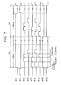
- Fig. 7 is a timing chart illustrating a practical example of the fourth type of operation described above. This operation is suitable for a color imaging apparatus which has a mosaic color filter provided on an imaging device having photo-sensors arranged in the manner shown in Fig. 1.
- pulses ⁇ V1 and ⁇ EF are set high, while the pulse ⁇ EO is set low, thereby turning on the transistors Q r1 and Q r2 corresponding to the scanning lines a and a+1 .
- the pulses ⁇ VC, ⁇ T1 and ⁇ T2 are set high, so as to turn on the transistors Q vc , Q t1 and Q t2 , thereby clearing the vertical lines VL, capacitors C1 and the capacitors C2.
- the transistors Q vc and Q t2 are turned off and the signals on the photo-sensors of the scanning line a are read in a non-destructive manner in accordance with the pulse ⁇ R1 and are stored in the capacitors C1.
- the pulses ⁇ FE and ⁇ FO are inverted so that the transistors Q o are turned on with the result that all the transistors Q r2 and Q r1 having gate electrodes connected to the transistors Q o are turned on, whereby the scanning lines a+1 and a+2 are selected.
- the capacitors C1 and C2 are cleared in this state and then the transistors Q t1 are turned on, so that the signals on the photo-sensors of the scanning line a+1 are read once again in accordance with the pulse ⁇ R1 and the thus read signals are stored in the capacitors C1.
- the vertical lines VL are cleared and, simultaneously, the photo-sensors of the scanning line a+1 are reset.
- the transistors Q t2 are turned on so that the signals on the photo-sensors of the scanning line a+2 are read in a non-destructive manner in accordance with the pulse ⁇ R2. The thus read signals are stored in the capacitors C2.
- signals (a+1) and a+2 derived from the scanning lines a+1 and a+2 , stored in the capacitors C1 and C2, are scanned by the horizontal scanning circuit 3 and are sequentially output through the signal lines S1 and S2.
- interpolation signals for interpolating the signals to be obtained from preceding and succeeding pixel lines can easily be formed by virtue of the non-destructive reading operation, whereby degradation in the vertical resolution can be avoided.
- FIGs. 8A and 8B are illustrations of vertical scanning and horizontal scanning of this mode of operation.
Landscapes
- Engineering & Computer Science (AREA)
- Multimedia (AREA)
- Signal Processing (AREA)
- Transforming Light Signals Into Electric Signals (AREA)
Claims (9)
- Un procédé pour faire fonctionner un appareil de formation d'image comprenant
un ensemble de pixels (1) disposés en lignes et en colonnes, et
des moyens de commande (5) pour commuter sélectivement le mode de fonctionnement de lecture entre un premier mode, dans lequel des signaux présents sur les pixels sont lus séquentiellement selon une première séquence et à une première vitesse, et un second mode, dans lequel des signaux présents sur une partie sélectionnée de l'étendue des pixels sont lus séquentiellement selon une seconde séquence différente de la première séquence, et avec une seconde vitesse différente de la première vitesse,
caractérisé en ce que
des paires de lignes adjacentes sont lues successivement en direction verticale dans chaque trame, et les paires de lignes adjacentes qui sont lues respectivement dans une trame de numéro impair et dans une trame de numéro pair, sont en chevauchement mutuel dans une même ligne. - Un appareil de formation d'image comprenant
un ensemble de pixels (1) disposés en lignes et en colonnes, et
des moyens de commande (5) pour commuter sélectivement le mode de fonctionnement de lecture entre un premier mode, dans lequel des signaux présents sur les pixels sont lus séquentiellement selon une première séquence et à une première vitesse, et un second mode, dans lequel des signaux présents sur une partie sélectionnée de l'étendue des pixels sont lus séquentiellement selon une seconde séquence différente de la première séquence, et avec une seconde vitesse différente de la première vitesse,
caractérisé par
des moyens grâce auxquels des paires de lignes adjacentes sont lues successivement en direction verticale dans chaque trame, et les paires de lignes adjacentes qui sont lues respectivement dans une trame de numéro impair et dans une trame de numéro pair sont en chevauchement mutuel dans une même ligne. - Un procédé selon la revendication 1 ou un appareil selon la revendication 2, caractérisé en ce que la seconde vitesse est supérieure à la première vitesse.
- Un procédé selon la revendication 1 ou un appareil selon la revendication 2, caractérisé en ce que la première séquence est une séquence pour la lecture séquentielle de signaux dans une ligne horizontale de pixels sur deux.
- Un procédé selon la revendication 1 ou un appareil selon la revendication 2, caractérisé en ce que la seconde séquence est une séquence pour la lecture séquentielle de signaux sur des lignes de pixels horizontales successives, en procédant ligne à ligne.
- Un procédé selon la revendication 1 ou un appareil selon la revendication 2, caractérisé en ce que la seconde séquence est une séquence dans laquelle des signaux sur une ligne horizontale de pixels sont lus un ensemble de fois, et ensuite les signaux sur une ligne horizontale de pixels suivante sont lus.
- Un procédé selon la revendication 1 ou un appareil selon la revendication 2, caractérisé en ce que la première séquence est une séquence dans laquelle des signaux sont lus simultanément à partir de pixels d'un groupe de lignes horizontales de pixels, et ensuite des signaux sont lus simultanément à partir de pixels d'un groupe suivant de lignes horizontales de pixels, pour effectuer ainsi une lecture simultanée de signaux provenant de chacun des groupes successifs de lignes horizontales de pixels.
- Un procédé selon la revendication 1 ou un appareil selon la revendication 2, caractérisé en ce que la seconde séquence est une séquence dans laquelle les signaux sont lus simultanément plusieurs fois à partir d'un groupe de lignes horizontales de pixels, et ensuite des signaux sont lus simultanément plusieurs fois à partir de pixels d'un groupe suivant de lignes horizontales de pixels, pour effectuer ainsi une lecture simultanée répétée de signaux provenant de chacun des groupes successifs de lignes horizontales de pixels.
- Un procédé selon la revendication ou un appareil selon la revendication 2, caractérisé en ce que la seconde séquence est une séquence dans laquelle des signaux sont lus simultanément à partir de pixels d'un premier groupe de lignes horizontales de pixels, et ensuite des signaux sont lus simultanément à partir de pixels d'un groupe suivant de lignes horizontales de pixels, ce groupe suivant de lignes horizontales de pixels comprenant au moins une ligne horizontale qui appartient au premier groupe de lignes horizontales, pour effectuer ainsi une lecture simultanée de signaux provenant de chacun des groupes successifs de lignes horizontales de pixels.
Applications Claiming Priority (2)
| Application Number | Priority Date | Filing Date | Title |
|---|---|---|---|
| JP62077953A JPS63245073A (ja) | 1987-03-31 | 1987-03-31 | 撮像装置 |
| JP77953/87 | 1987-03-31 |
Publications (2)
| Publication Number | Publication Date |
|---|---|
| EP0285894A1 EP0285894A1 (fr) | 1988-10-12 |
| EP0285894B1 true EP0285894B1 (fr) | 1993-09-01 |
Family
ID=13648373
Family Applications (1)
| Application Number | Title | Priority Date | Filing Date |
|---|---|---|---|
| EP88104506A Expired - Lifetime EP0285894B1 (fr) | 1987-03-31 | 1988-03-21 | Appareil de prise de vues |
Country Status (4)
| Country | Link |
|---|---|
| US (1) | US4876601A (fr) |
| EP (1) | EP0285894B1 (fr) |
| JP (1) | JPS63245073A (fr) |
| DE (1) | DE3883577T2 (fr) |
Families Citing this family (16)
| Publication number | Priority date | Publication date | Assignee | Title |
|---|---|---|---|---|
| KR920003656B1 (ko) * | 1988-04-01 | 1992-05-06 | 샤프 가부시끼 가이샤 | 전자적으로 화상을 확대하여 촬영이 가능한 촬상 장치 |
| JP2539682B2 (ja) * | 1989-04-04 | 1996-10-02 | シャープ株式会社 | 電子的に拡大撮影可能な撮像装置 |
| US5172249A (en) * | 1989-05-31 | 1992-12-15 | Canon Kabushiki Kaisha | Photoelectric converting apparatus with improved switching to reduce sensor noises |
| JPH03117275A (ja) * | 1989-09-29 | 1991-05-20 | Sanyo Electric Co Ltd | オートフォーカスカメラ |
| US5146339A (en) * | 1989-11-21 | 1992-09-08 | Canon Kabushiki Kaisha | Photoelectric converting apparatus employing Darlington transistor readout |
| JP2991354B2 (ja) * | 1990-11-07 | 1999-12-20 | キヤノン株式会社 | 画像読取装置およびそれを備えた画像情報処理装置 |
| KR930012203B1 (ko) * | 1991-01-09 | 1993-12-24 | 삼성전자 주식회사 | 특정부위 확대 녹화방법 및 장치 |
| JP3216907B2 (ja) * | 1992-05-18 | 2001-10-09 | 株式会社日立製作所 | 電子ズーム装置及び撮像装置 |
| WO1997017800A1 (fr) * | 1995-11-07 | 1997-05-15 | California Institute Of Technology | Capteur d'image dote d'une sortie lineaire a dynamique elevee |
| US6977684B1 (en) | 1998-04-30 | 2005-12-20 | Canon Kabushiki Kaisha | Arrangement of circuits in pixels, each circuit shared by a plurality of pixels, in image sensing apparatus |
| US6956605B1 (en) | 1998-08-05 | 2005-10-18 | Canon Kabushiki Kaisha | Image pickup apparatus |
| US6734906B1 (en) | 1998-09-02 | 2004-05-11 | Canon Kabushiki Kaisha | Image pickup apparatus with photoelectric conversion portions arranged two dimensionally |
| JP2001024949A (ja) | 1999-07-08 | 2001-01-26 | Canon Inc | 固体撮像装置及びそれを用いた撮像システム |
| JP3548465B2 (ja) | 1999-09-08 | 2004-07-28 | キヤノン株式会社 | 撮像装置及び撮像方法 |
| JP3937716B2 (ja) | 2000-10-24 | 2007-06-27 | キヤノン株式会社 | 固体撮像装置及び撮像システム |
| JP2006311051A (ja) * | 2005-04-27 | 2006-11-09 | Matsushita Electric Ind Co Ltd | 固体撮像素子用の信号処理回路および固体撮像装置 |
Family Cites Families (16)
| Publication number | Priority date | Publication date | Assignee | Title |
|---|---|---|---|---|
| US3935381A (en) * | 1974-06-24 | 1976-01-27 | The United States Of America As Represented By The Secretary Of The Navy | Electronic solid state sensor image size control |
| US4002824A (en) * | 1976-01-28 | 1977-01-11 | The United States Of America As Represented By The Secretary Of The Navy | Selective zoom camera and display |
| DE2725362C3 (de) * | 1977-06-04 | 1980-08-28 | Robert Bosch Gmbh, 7000 Stuttgart | Verfahren zum Verarbeiten von Farbfernsehsignalen |
| DE2913116A1 (de) * | 1979-04-02 | 1980-10-23 | Bosch Gmbh Robert | Verfahren zum auslesen von festkoerper- bildsensoren und schaltungsanordnung zur durchfuehrung des verfahrens |
| JPS57178479A (en) * | 1981-04-27 | 1982-11-02 | Sony Corp | Solid image pickup element |
| US4546349A (en) * | 1981-09-29 | 1985-10-08 | Sperry Corporation | Local zoom for raster scan displays |
| JPS58137371A (ja) * | 1982-02-10 | 1983-08-15 | Hitachi Ltd | 固体撮像装置 |
| DE3478779D1 (en) * | 1983-02-15 | 1989-07-27 | Sharp Kk | Two-dimensional image readout device |
| JPS6032488A (ja) * | 1983-08-02 | 1985-02-19 | Canon Inc | 撮像装置 |
| JPS60160780A (ja) * | 1984-01-31 | 1985-08-22 | Nec Corp | 特殊効果用画像記憶装置 |
| US4658287A (en) * | 1984-02-29 | 1987-04-14 | Fairchild Camera And Instrument Corp. | MOS imaging device with monochrome-color compatibility and signal readout versatility |
| FR2566219B1 (fr) * | 1984-06-15 | 1989-04-28 | Sfim | Procede et dispositif pour l'exploration d'une fenetre de la zone image d'un dispositif a transfert de charges du type a transfert de trames |
| US4706122A (en) * | 1984-08-30 | 1987-11-10 | Nec Corporation | Solid-state imaging device compatible with different television systems |
| GB2170974B (en) * | 1985-02-07 | 1988-01-06 | Rank Cintel Ltd | Telecine projector line array sensor |
| FR2588709B1 (fr) * | 1985-10-16 | 1988-07-29 | Thomson Csf | Systeme de grossissement d'une partie d'une image dans les dispositifs de prise de vues video notamment a senseur a transfert de charges |
| JPH0642726B2 (ja) * | 1985-10-18 | 1994-06-01 | キヤノン株式会社 | 固体撮像装置 |
-
1987
- 1987-03-31 JP JP62077953A patent/JPS63245073A/ja active Pending
-
1988
- 1988-03-15 US US07/168,176 patent/US4876601A/en not_active Expired - Lifetime
- 1988-03-21 DE DE88104506T patent/DE3883577T2/de not_active Expired - Fee Related
- 1988-03-21 EP EP88104506A patent/EP0285894B1/fr not_active Expired - Lifetime
Also Published As
| Publication number | Publication date |
|---|---|
| DE3883577T2 (de) | 1994-02-17 |
| US4876601A (en) | 1989-10-24 |
| DE3883577D1 (de) | 1993-10-07 |
| EP0285894A1 (fr) | 1988-10-12 |
| JPS63245073A (ja) | 1988-10-12 |
Similar Documents
| Publication | Publication Date | Title |
|---|---|---|
| EP0346102B1 (fr) | Dispositif capteur d'image à l'état solide | |
| US7804540B2 (en) | Image pickup apparatus having a plurality of different readout modes | |
| JP3511772B2 (ja) | 固体撮像素子、固体撮像素子の駆動方法、カメラ装置及びカメラシステム | |
| US4876601A (en) | Imaging apparatus having zoom capability via readout variation | |
| US7002630B1 (en) | Method of driving solid-state imaging device, solid-state imaging device and camera | |
| JP3906496B2 (ja) | 固体撮像装置およびその駆動方法、並びにカメラ | |
| US5287192A (en) | Solid-state imager for use with two different TV systems | |
| EP0569202A2 (fr) | Capteur d'images à l'état solide avec obturateur électronique | |
| JPH09247689A (ja) | カラー撮像装置 | |
| EP0449210B1 (fr) | Dispositif pour zoom électronique | |
| JP3920085B2 (ja) | 固体撮像装置とそのスミア補正方法並びにデジタルスチルカメラ | |
| US4298891A (en) | Television receiver | |
| EP0876053B1 (fr) | Procédé de commande d'un capteur d'images à l'état solide | |
| US6760069B2 (en) | Method and apparatus for processing image signals | |
| JPH0695735B2 (ja) | 固体撮像装置 | |
| US8045025B2 (en) | Image pickup device adaptable to display fewer vertical pixels | |
| US7535505B2 (en) | Imaging device and a digital camera having same in which pixel signals read from the pixel block are horizontally transferred in a collective fashion | |
| JPS6043704B2 (ja) | 固体撮像装置 | |
| JPH09233394A (ja) | 撮像装置 | |
| JPS62291269A (ja) | 固体カラ−撮像装置 | |
| JPH10285467A (ja) | 撮像装置 | |
| US6355949B1 (en) | Solid state imaging apparatus with horizontal charge transfer register which can transfer signal charge faster | |
| JP2000308075A (ja) | 撮像素子および撮像素子の駆動方法 | |
| JP2897665B2 (ja) | 固体撮像素子の駆動方法 | |
| JP2658443B2 (ja) | 固体撮像装置の駆動方法 |
Legal Events
| Date | Code | Title | Description |
|---|---|---|---|
| PUAI | Public reference made under article 153(3) epc to a published international application that has entered the european phase |
Free format text: ORIGINAL CODE: 0009012 |
|
| AK | Designated contracting states |
Kind code of ref document: A1 Designated state(s): DE FR GB IT NL |
|
| 17P | Request for examination filed |
Effective date: 19890222 |
|
| 17Q | First examination report despatched |
Effective date: 19910902 |
|
| GRAA | (expected) grant |
Free format text: ORIGINAL CODE: 0009210 |
|
| AK | Designated contracting states |
Kind code of ref document: B1 Designated state(s): DE FR GB IT NL |
|
| PG25 | Lapsed in a contracting state [announced via postgrant information from national office to epo] |
Ref country code: IT Free format text: LAPSE BECAUSE OF FAILURE TO SUBMIT A TRANSLATION OF THE DESCRIPTION OR TO PAY THE FEE WITHIN THE PRE;WARNING: LAPSES OF ITALIAN PATENTS WITH EFFECTIVE DATE BEFORE 2007 MAY HAVE OCCURRED AT ANY TIME BEFORE 2007. THE CORRECT EFFECTIVE DATE MAY BE DIFFERENT FROM THE ONE RECORDED.SCRIBED TIME-LIMIT Effective date: 19930901 Ref country code: NL Effective date: 19930901 |
|
| REF | Corresponds to: |
Ref document number: 3883577 Country of ref document: DE Date of ref document: 19931007 |
|
| ET | Fr: translation filed | ||
| NLV1 | Nl: lapsed or annulled due to failure to fulfill the requirements of art. 29p and 29m of the patents act | ||
| PG25 | Lapsed in a contracting state [announced via postgrant information from national office to epo] |
Ref country code: GB Effective date: 19940321 |
|
| PLBE | No opposition filed within time limit |
Free format text: ORIGINAL CODE: 0009261 |
|
| STAA | Information on the status of an ep patent application or granted ep patent |
Free format text: STATUS: NO OPPOSITION FILED WITHIN TIME LIMIT |
|
| 26N | No opposition filed | ||
| GBPC | Gb: european patent ceased through non-payment of renewal fee |
Effective date: 19940321 |
|
| PGFP | Annual fee paid to national office [announced via postgrant information from national office to epo] |
Ref country code: FR Payment date: 20060308 Year of fee payment: 19 |
|
| PGFP | Annual fee paid to national office [announced via postgrant information from national office to epo] |
Ref country code: DE Payment date: 20060316 Year of fee payment: 19 |
|
| REG | Reference to a national code |
Ref country code: FR Ref legal event code: ST Effective date: 20071130 |
|
| PG25 | Lapsed in a contracting state [announced via postgrant information from national office to epo] |
Ref country code: DE Free format text: LAPSE BECAUSE OF NON-PAYMENT OF DUE FEES Effective date: 20071002 |
|
| PG25 | Lapsed in a contracting state [announced via postgrant information from national office to epo] |
Ref country code: FR Free format text: LAPSE BECAUSE OF NON-PAYMENT OF DUE FEES Effective date: 20070402 |