EP0285921A2 - Procédé et installation de broyage de matériau fragile - Google Patents
Procédé et installation de broyage de matériau fragile Download PDFInfo
- Publication number
- EP0285921A2 EP0285921A2 EP88104784A EP88104784A EP0285921A2 EP 0285921 A2 EP0285921 A2 EP 0285921A2 EP 88104784 A EP88104784 A EP 88104784A EP 88104784 A EP88104784 A EP 88104784A EP 0285921 A2 EP0285921 A2 EP 0285921A2
- Authority
- EP
- European Patent Office
- Prior art keywords
- plant
- digestion unit
- mill
- roller mill
- screen classifier
- Prior art date
- Legal status (The legal status is an assumption and is not a legal conclusion. Google has not performed a legal analysis and makes no representation as to the accuracy of the status listed.)
- Granted
Links
Images


Classifications
-
- B—PERFORMING OPERATIONS; TRANSPORTING
- B02—CRUSHING, PULVERISING, OR DISINTEGRATING; PREPARATORY TREATMENT OF GRAIN FOR MILLING
- B02C—CRUSHING, PULVERISING, OR DISINTEGRATING IN GENERAL; MILLING GRAIN
- B02C23/00—Auxiliary methods or auxiliary devices or accessories specially adapted for crushing or disintegrating not provided for in preceding groups or not specially adapted to apparatus covered by a single preceding group
- B02C23/08—Separating or sorting of material, associated with crushing or disintegrating
- B02C23/10—Separating or sorting of material, associated with crushing or disintegrating with separator arranged in discharge path of crushing or disintegrating zone
- B02C23/12—Separating or sorting of material, associated with crushing or disintegrating with separator arranged in discharge path of crushing or disintegrating zone with return of oversize material to crushing or disintegrating zone
-
- B—PERFORMING OPERATIONS; TRANSPORTING
- B02—CRUSHING, PULVERISING, OR DISINTEGRATING; PREPARATORY TREATMENT OF GRAIN FOR MILLING
- B02C—CRUSHING, PULVERISING, OR DISINTEGRATING IN GENERAL; MILLING GRAIN
- B02C21/00—Disintegrating plant with or without drying of the material
- B02C21/002—Disintegrating plant with or without drying of the material using a combination of a roller mill and a drum mill
- B02C21/005—Disintegrating plant with or without drying of the material using a combination of a roller mill and a drum mill the roller mill having cooperating rollers
-
- B—PERFORMING OPERATIONS; TRANSPORTING
- B02—CRUSHING, PULVERISING, OR DISINTEGRATING; PREPARATORY TREATMENT OF GRAIN FOR MILLING
- B02C—CRUSHING, PULVERISING, OR DISINTEGRATING IN GENERAL; MILLING GRAIN
- B02C23/00—Auxiliary methods or auxiliary devices or accessories specially adapted for crushing or disintegrating not provided for in preceding groups or not specially adapted to apparatus covered by a single preceding group
- B02C23/18—Adding fluid, other than for crushing or disintegrating by fluid energy
Definitions
- the invention relates to a comminution method according to the preamble of claim 1 and a system according to the preamble of claim 7.
- a method according to the preamble of claim 1 (or a system according to the preamble of claim 7) is known from Fig. 6 of EP-A-84 383.
- the material shredded in the roller mill is fed directly to a screen classifier.
- the oversize is fed from the screen classifier to the tube mill (a part can also be returned to the roller mill).
- the portion of the product that passes through the screen classifier, together with the material discharged from the tube mill, reaches a sifter, the fine material of which forms the finished product, while the semolina are fed back to the tube mill (or in part back to the roller mill).
- a disadvantage of this known method is furthermore that the oversize that accumulates in the screen classifier can be conveyed pneumatically or hydraulically to the tube mill only with very high energy expenditure with regard to the size of the slugs.
- This disadvantage is particularly significant if, for technical reasons, the roller mill and the tube mill have to be arranged far apart (for example, because in a cement production facility the roller mill is close to the clinker cooler and thus spatially far away from that containing the tube mill Circulating grinding plant must be arranged or because in a mine the roller mill must be installed at the mining site, but the tube mill is located in the processing plant - also far away from the roller mill).
- the earlier application DE-A-36 09 229 also relates to a process for comminuting brittle regrind, in which the regrind is first comminuted in a roller mill and then undergoes a treatment to dissolve agglomerates, after which the regrind is sifted and the the size of the grains which are produced are further crushed.
- the invention has for its object to develop a method according to the preamble of claim 1 that the size and required drive power of the roller mill is reduced, the operating conditions in the roller mill and in the subsequent further comminution stage are improved and the overall energy consumption (including the energy consumption for conveying the ground material) is reduced.
- a system according to the invention is the subject of claim 7.
- the regrind undergoes a treatment to dissolve agglomerates after the first comminution stage, but before the sieve classification. In this way, the fine material contained in the slugs is exposed before the subsequent sieve classification.
- the portion of the product which passes through the screen classifier and which is well calibrated e.g. 100% below 5 mm
- the portion of the product which passes through the screen classifier and which is well calibrated can be pneumatically (with dry grinding) or hydraulically (with wet) with little energy expenditure and little wear Grinding) to the downstream circulation system (which preferably contains a tube mill and a sifter or hydrocyclone).
- the roller mill can be dimensioned much smaller and requires less drive power.
- the product which has been well calibrated by the sieve classifier (after previous digestion), can be stored in silos without the risk of segregation.
- the process according to the invention also significantly improves the operating conditions both in the roller mill and in the downstream tube mill.
- regrind which is poorly absorbed (for example clinker or ore)
- a significant increase and homogenization of the specific throughput of the roller mill can be determined.
- the operating conditions in the tube mill are substantially evened out by the calibration of the ground material achieved by means of the sieve classification (after previous digestion).
- the method according to the invention is particularly suitable when the roller mill has to be arranged spatially far from the tube mill, for example if in the area roller mill arranged in the furnace or cooler must be supplied with cement mills (tube mills) which are arranged far away, for example in a separate grinder.
- the method according to the invention allows hydraulic transport, which is also very energy-saving and low-wear, in cases in which the roller mill in a mine the vicinity of the mining site, for example underground, is set up, but the tube mills to be supplied are arranged far away in the processing plant for days.
- the digestion unit arranged according to the invention between the roller mill and the screen classifier can be, for example, a hammer mill which runs at a low peripheral speed (preferably 20 to 30 m / s), the material being discharged from the hammer mill either in an air stream or through a grate floor.
- Another suitable form of the digestion unit is an impact mill with fixed impact strips, the material discharge advantageously being carried out through a grate floor.
- the digestion unit is formed by a disintegrator with a central feed and peripheral discharge.
- Another advantageous variant provides as a digestion unit a Simpson mixer, which contains a turnstile equipped with rollers and plowshares, the rollers maintaining an adjustable minimum distance from the bottom of the mixer, so that only digestion, no grinding of the product passing through the mixer takes place.
- digestion methods or digestion units relate to the grinding of dry or moist ground material.
- the agglomerated ground material is broken down by adding liquid (preferably water) to adjust the liquid content of the slurry required for transport by pumps and / or for wet classification.
- liquid preferably water
- the digestion takes place simply by adding liquid, i.e. without further action; experience shows that the flakes of brittle regrind disintegrate very easily.
- the agglomerates are dissolved by the energy contained in the added liquid in or on the classifying unit, which is preferably a curved screen.
- Another variant which is particularly useful for regrind with greater strength of the agglomerates, provides as a digestion unit a mixing vessel in which the mechanical energy required for the digestion is supplied by an agitator or another suitable device.
- the mesh size of the screen classifier can be used be chosen moderately with 3 to 8 mm.
- the screen classifier should therefore only cut off the coarse grain fraction (for example over 5 mm). This leads to a circulation factor (in the circle formed by the roller mill, the digestion unit and the screen classifier, based on the amount of the regrind fed) from 1.1 to 1.3.
- Such a screen classifier is much cheaper than a classifier that should look out for finished products and consequently cannot be subjected to as high a load as a screen classifier that only cuts off the coarse grain fraction.
- 1 contains a rotary kiln 1 with a clinker cooler 2 designed as a planetary cooler.
- the material is fed to a roller mill 4, in which the ground material is comminuted using high pressure and the formation of agglomerates.
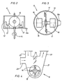
- the product discharged from the roller mill 4 passes into a digestion unit 5 which is designed, for example, as a Simpson mixer (FIGS. 2, 3) or as a hammer mill (FIG. 4).
- a digestion unit 5 which is designed, for example, as a Simpson mixer (FIGS. 2, 3) or as a hammer mill (FIG. 4).
- the ground material arrives at a screen classifier 6, the oversize of which is conveyed back to the roller mill 4.
- the portion of the screen classifier 6 assisting of the comminuted in the roller mill 4 and broken down in the pulping unit 5 is fed to a silo 8 via a pneumatic conveying path 7, for example.
- the pre-shredded material passes through a distributor 9 to parallel grinding plants 10, 10 ⁇ , 10 ⁇ , each consisting of a tube mill 11 and a sifter 12.
- FIGS. 2 and 3 illustrate a Simpson mixer as an embodiment of the digestion unit 5. It contains in a fixed housing 13 with a discharge chute 13a a turnstile 15 driven by a shaft 14, which is equipped with rollers 16 and plowshares 17.
- the rollers 16 maintain an adjustable minimum distance from the bottom of the housing 13, so that the material in the digestion unit 5 is not ground, but only broken down, i. H. the fines content from the slugs is exposed.
- Fig. 4 illustrates as a digestion unit 5, a hammer mill, the rotor 18 carries swinging hammers 19.
- the ground material is introduced into the mill housing 21 through a nozzle 20 and discharged pneumatically through a nozzle 22.
- the flow rate of the air supplied via a nozzle 23 is adjusted by means of flaps 24.
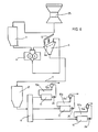
- FIG. 5 shows a variant of the system diagram illustrated in FIG. 1.
- FIG. 5 shows this scheme of the circulation grinding plant 10, which is suitable for many applications.
- the sifter 12 can be designed as a two-stage sifter, the first stage being set relatively roughly (separating cut, for example at 300 ⁇ m) and the fine material being checked in a second stage, the separating cut of which is, for example, 12 to 20 ⁇ m.
- variant a requires a larger roller mill (with a correspondingly higher drive power) than variant b according to the invention.
- the system contains a gyratory crusher 25 as the primary crusher, from which the pre-shredded ground material arrives in the intermediate bunker 3, from which it is then fed to the roller mill 4.
- the product discharged from the roller mill 4 arrives immediately upstream of the screen classifier 6 to a digestion unit 5 'formed by a spray device, through which liquid, preferably water, is fed to the regrind falling on a curved screen 6a of the screen classifier 6.
- the digestion and the classification of the regrind are supported by the liquid supply.
- the oversize grain is conveyed to the roller mill 4, while the portion passing through the screen classifier 6 reaches a storage container 8 ⁇ via a hydraulic conveying path 7, for example.
- the pre-ground and calibrated material is fed via a distributor 9 to the parallel wet grinding systems 10a, 10 ⁇ a, 10 ⁇ a, which each consist of a tube mill 11, a feed pump 26 and a classifier 12a (preferably a hydrocyclone).
Landscapes
- Engineering & Computer Science (AREA)
- Food Science & Technology (AREA)
- Crushing And Grinding (AREA)
- Disintegrating Or Milling (AREA)
Applications Claiming Priority (2)
| Application Number | Priority Date | Filing Date | Title |
|---|---|---|---|
| DE19873712147 DE3712147A1 (de) | 1987-04-10 | 1987-04-10 | Verfahren und anlage zur zerkleinerung von sproedem mahlgut |
| DE3712147 | 1987-04-10 |
Publications (3)
| Publication Number | Publication Date |
|---|---|
| EP0285921A2 true EP0285921A2 (fr) | 1988-10-12 |
| EP0285921A3 EP0285921A3 (en) | 1989-10-04 |
| EP0285921B1 EP0285921B1 (fr) | 1992-09-30 |
Family
ID=6325311
Family Applications (1)
| Application Number | Title | Priority Date | Filing Date |
|---|---|---|---|
| EP88104784A Expired - Lifetime EP0285921B1 (fr) | 1987-04-10 | 1988-03-24 | Procédé et installation de broyage de matériau fragile |
Country Status (8)
| Country | Link |
|---|---|
| US (1) | US5154362A (fr) |
| EP (1) | EP0285921B1 (fr) |
| AU (1) | AU598122B2 (fr) |
| BR (1) | BR8801583A (fr) |
| DE (2) | DE3712147A1 (fr) |
| DK (1) | DK194588A (fr) |
| ES (1) | ES2035132T3 (fr) |
| ZA (1) | ZA881934B (fr) |
Cited By (6)
| Publication number | Priority date | Publication date | Assignee | Title |
|---|---|---|---|---|
| EP0727256A1 (fr) * | 1995-02-14 | 1996-08-21 | Krupp Polysius Ag | Procédé et dispositif de broyage de matières minérales humides |
| RU2185244C2 (ru) * | 2000-07-27 | 2002-07-20 | Баев Владимир Сергеевич | Способ получения жидкого композиционного топлива и дезинтегратор и устройство гидроударного действия для его осуществления |
| US9067213B2 (en) | 2008-07-02 | 2015-06-30 | Buhler Ag | Method for producing flour and/or semolina |
| CN105855022A (zh) * | 2016-06-06 | 2016-08-17 | 临汾市鑫锐机械设备有限公司 | 三转子组合破碎机 |
| CN107511205A (zh) * | 2016-06-15 | 2017-12-26 | 许云飞 | 一种用于酱油生产中的破碎机 |
| EP3895806A1 (fr) * | 2020-04-15 | 2021-10-20 | Elena Vladimirovna Artemieva | Dispositif et procédé de broyage de matières solides |
Families Citing this family (14)
| Publication number | Priority date | Publication date | Assignee | Title |
|---|---|---|---|---|
| DE3822729A1 (de) * | 1988-07-05 | 1990-01-11 | Krupp Polysius Ag | Anlage zur zerkleinerung von sproedem mahlgut |
| DE3921823A1 (de) * | 1989-07-03 | 1991-01-17 | Krupp Polysius Ag | Verfahren und anlage zur zerkleinerung von mahlgut |
| DD298600A5 (de) * | 1989-09-15 | 1992-03-05 | Forschungsinstitut Fuer Aufbereitung,De | Rohrkugelmuehlen zur effektiven desagglomeration und zerkleinerung von hochdruckzerkleinertem sproeden material |
| FR2670135B1 (fr) * | 1990-12-06 | 1993-03-26 | Cle | Procede de broyage de matieres cassantes comportant pour la mise en óoeuvre du procede une desagglomeration selective et installation. |
| DE4137901C2 (de) * | 1991-11-18 | 1998-10-01 | Bernd Dipl Chem Dr Kroeckert | Verfahren zur Strahlmahlung von anorganischen Pigmenten |
| DE4239602A1 (de) * | 1992-11-25 | 1994-05-26 | Krupp Polysius Ag | Verfahren und Vorrichtung zur Zerkleinerung von Mahlgut |
| DE19512509B4 (de) * | 1995-04-04 | 2009-07-30 | Polysius Ag | Verfahren zur Zerkleinerung von Erzmaterial |
| DE19626387C2 (de) * | 1996-07-01 | 2003-05-28 | Polysius Ag | Verfahren zur Gewinnung von Metall aus Erzmaterial |
| US6197104B1 (en) | 1998-05-04 | 2001-03-06 | Millennium Inorganic Chemicals, Inc. | Very high solids TiO2 slurries |
| RU2317319C1 (ru) * | 2006-11-15 | 2008-02-20 | Федеральное государственное унитарное предприятие "Институт горючих ископаемых-научно-технический центр по комплексной переработке твердых горючих ископаемых" (ФГУП ИГИ) | Способ получения топливной суспензии |
| CN103861707B (zh) * | 2014-04-03 | 2015-09-23 | 张天娇 | 深采矿山矿石的破碎运输方法及破碎运输系统 |
| CN103861708B (zh) * | 2014-04-03 | 2015-11-18 | 张天娇 | 深采矿山铁矿石的破碎运输方法及破碎运输系统 |
| DE102014014945A1 (de) * | 2014-10-09 | 2016-04-14 | Micro Impact Mill Limited | Vorrichtung und Verfahren zum Erzzerkleinern mit einer hydraulischen Federeinrichtung |
| CN105233951B (zh) * | 2015-11-01 | 2017-07-14 | 宁波平海建材有限公司 | 黏土浆的处理系统 |
Family Cites Families (10)
| Publication number | Priority date | Publication date | Assignee | Title |
|---|---|---|---|---|
| US2826370A (en) * | 1953-03-02 | 1958-03-11 | Weston David | Moisture control of feed material in systems including both combined dry crushing-and-grinding mills and wet grinding mills |
| DE3334235A1 (de) * | 1982-11-04 | 1984-05-10 | Heinz 4630 Bochum Jäger | Verfahren und vorrichtung zur energiesparenden herstellung eines feingutes, insbesondere zement |
| DE3302176A1 (de) * | 1983-01-24 | 1984-07-26 | Klöckner-Humboldt-Deutz AG, 5000 Köln | Verfahren und anlage zur kontinuierlichen druckzerkleinerung sproeden mahlgutes |
| DE3314103A1 (de) * | 1983-04-19 | 1984-10-25 | Klöckner-Humboldt-Deutz AG, 5000 Köln | Verfahren und anlage zur gemeinsamen mahlung zweier oder mehrerer unterschiedlich mahlbarer sproeder stoffe |
| DE3337615A1 (de) * | 1983-10-15 | 1985-04-25 | Klöckner-Humboldt-Deutz AG, 5000 Köln | Verfahren und anlage zur zerkleinerung, mahlung und aufbereitung gruben- oder naturfeuchter mineralischer rohstoffe wie erze oder dergleichen |
| DE3506486A1 (de) * | 1985-02-23 | 1986-08-28 | Klöckner-Humboldt-Deutz AG, 5000 Köln | Einrichtung zur zerkleinerung und mahlung sproeden mahlgutes wie zum beispiel zementklinker, erz, kohle oder dergleichen |
| DE3518543C3 (de) * | 1985-05-23 | 1996-12-19 | Kloeckner Humboldt Deutz Ag | Verfahren und Einrichtung zur Zerkleinerung bzw. Mahlung spröden Mahlgutes |
| EP0220681B1 (fr) * | 1985-10-29 | 1991-05-29 | Klöckner-Humboldt-Deutz Aktiengesellschaft | Installation pour fractionner et broyer des matériaux fragiles et mouillés |
| DE3544798C2 (de) * | 1985-10-29 | 1995-04-20 | Kloeckner Humboldt Deutz Ag | Einrichtung zur Zerkleinerung und Mahlung und Trocknung (Mahltrocknung) von feuchtem Gut |
| DE3609229A1 (de) * | 1986-03-19 | 1987-09-24 | Krupp Polysius Ag | Verfahren und anlage zur zerkleinerung von sproedem mahlgut |
-
1987
- 1987-04-10 DE DE19873712147 patent/DE3712147A1/de not_active Withdrawn
-
1988
- 1988-03-18 ZA ZA881934A patent/ZA881934B/xx unknown
- 1988-03-24 DE DE8888104784T patent/DE3874933D1/de not_active Expired - Fee Related
- 1988-03-24 EP EP88104784A patent/EP0285921B1/fr not_active Expired - Lifetime
- 1988-03-24 ES ES198888104784T patent/ES2035132T3/es not_active Expired - Lifetime
- 1988-04-04 BR BR8801583A patent/BR8801583A/pt not_active IP Right Cessation
- 1988-04-08 DK DK194588A patent/DK194588A/da not_active Application Discontinuation
- 1988-04-08 AU AU14418/88A patent/AU598122B2/en not_active Ceased
-
1989
- 1989-10-23 US US07/426,505 patent/US5154362A/en not_active Expired - Fee Related
Cited By (7)
| Publication number | Priority date | Publication date | Assignee | Title |
|---|---|---|---|---|
| EP0727256A1 (fr) * | 1995-02-14 | 1996-08-21 | Krupp Polysius Ag | Procédé et dispositif de broyage de matières minérales humides |
| RU2185244C2 (ru) * | 2000-07-27 | 2002-07-20 | Баев Владимир Сергеевич | Способ получения жидкого композиционного топлива и дезинтегратор и устройство гидроударного действия для его осуществления |
| US9067213B2 (en) | 2008-07-02 | 2015-06-30 | Buhler Ag | Method for producing flour and/or semolina |
| US10981177B2 (en) | 2008-07-02 | 2021-04-20 | Bühler AG | Apparatus and method for producing flour and/or semolina |
| CN105855022A (zh) * | 2016-06-06 | 2016-08-17 | 临汾市鑫锐机械设备有限公司 | 三转子组合破碎机 |
| CN107511205A (zh) * | 2016-06-15 | 2017-12-26 | 许云飞 | 一种用于酱油生产中的破碎机 |
| EP3895806A1 (fr) * | 2020-04-15 | 2021-10-20 | Elena Vladimirovna Artemieva | Dispositif et procédé de broyage de matières solides |
Also Published As
| Publication number | Publication date |
|---|---|
| EP0285921A3 (en) | 1989-10-04 |
| DE3712147A1 (de) | 1988-10-20 |
| DK194588A (da) | 1988-10-11 |
| ZA881934B (en) | 1988-09-08 |
| DK194588D0 (da) | 1988-04-08 |
| DE3874933D1 (de) | 1992-11-05 |
| AU598122B2 (en) | 1990-06-14 |
| BR8801583A (pt) | 1988-11-08 |
| AU1441888A (en) | 1988-10-13 |
| US5154362A (en) | 1992-10-13 |
| EP0285921B1 (fr) | 1992-09-30 |
| ES2035132T3 (es) | 1993-04-16 |
Similar Documents
| Publication | Publication Date | Title |
|---|---|---|
| EP0285921B1 (fr) | Procédé et installation de broyage de matériau fragile | |
| EP0193033B1 (fr) | Dispositif de broyage et de mouture de matière à moudre fragile comme par exemple le clinker, le minerai, le charbon et analogues | |
| EP0384101B1 (fr) | Séparateur pneumatique pour trier des matériaux granulaires et installation de broyage comportant un tel séparateur | |
| EP0603481B1 (fr) | Procédé et installation pour le broyage de matière à moudre | |
| EP2024091B1 (fr) | Presse à rouleaux notamment pour le broyage d'un lit de matière | |
| DE3719251A1 (de) | Verfahren und anlage zur kontinuierlichen druckzerkleinerung sproeden mahlgutes | |
| EP0084383A2 (fr) | Procédé de broyage continu par compression de matériau friable | |
| EP0220681A2 (fr) | Installation pour fractionner et broyer des matériaux fragiles et mouillés | |
| DE19512509A1 (de) | Verfahren zur Zerkleinerung von Erzmaterial | |
| EP3154701A1 (fr) | Installation de broyage et procédé de concassage de matière à broyer | |
| DE69215751T2 (de) | Vorrichtung und Verfahren zur Zerkleinerung | |
| WO2010072276A1 (fr) | Procédé et dispositif pour désagréger de la matière minérale à broyer | |
| EP0413155A2 (fr) | Installation de broyage à recyclage pour matière fragile | |
| DE3518543C3 (de) | Verfahren und Einrichtung zur Zerkleinerung bzw. Mahlung spröden Mahlgutes | |
| EP0403778B1 (fr) | Procédé d'exploitation d'une installation de broyage pour matériau friable | |
| EP0727256A1 (fr) | Procédé et dispositif de broyage de matières minérales humides | |
| DE3337615A1 (de) | Verfahren und anlage zur zerkleinerung, mahlung und aufbereitung gruben- oder naturfeuchter mineralischer rohstoffe wie erze oder dergleichen | |
| DE102013110881B4 (de) | Zerkleinerungsanlage und Verfahren zur Erzeugung eines Feinerzproduktes | |
| DE19519516C2 (de) | Verfahren und Vorrichtung zur Aufbereitung von Faserbestandteile und Fremdbestandteile enthaltenden Faserstoffen, insbesondere von Alt-Mineralwolle | |
| EP0610573A2 (fr) | Procédé de broyage et installation associée | |
| EP0237641B1 (fr) | Installation pour le broyage de matière à broyer fragile | |
| EP3655164B1 (fr) | Circuit de mouture à deux étages et procédé pour produire un produit moulu à coup de mouture à deux étages | |
| EP3074137B1 (fr) | Procédé de fabrication de ciment | |
| DE4307230A1 (de) | Verfahren und Anlage zur Gutbettzerkleinerung von sprödem Mahlgut | |
| DE3711926A1 (de) | Einrichtung zur zerkleinerung und mahlung sproeden mahlgutes wie z. b. zementklinker, erz, kohle oder dergleichen |
Legal Events
| Date | Code | Title | Description |
|---|---|---|---|
| PUAI | Public reference made under article 153(3) epc to a published international application that has entered the european phase |
Free format text: ORIGINAL CODE: 0009012 |
|
| AK | Designated contracting states |
Kind code of ref document: A2 Designated state(s): BE DE ES FR GB IT |
|
| PUAL | Search report despatched |
Free format text: ORIGINAL CODE: 0009013 |
|
| AK | Designated contracting states |
Kind code of ref document: A3 Designated state(s): BE DE ES FR GB IT |
|
| 17P | Request for examination filed |
Effective date: 19900116 |
|
| 17Q | First examination report despatched |
Effective date: 19900612 |
|
| GRAA | (expected) grant |
Free format text: ORIGINAL CODE: 0009210 |
|
| AK | Designated contracting states |
Kind code of ref document: B1 Designated state(s): BE DE ES FR GB IT |
|
| GBT | Gb: translation of ep patent filed (gb section 77(6)(a)/1977) | ||
| REF | Corresponds to: |
Ref document number: 3874933 Country of ref document: DE Date of ref document: 19921105 |
|
| ITF | It: translation for a ep patent filed | ||
| ET | Fr: translation filed | ||
| PGFP | Annual fee paid to national office [announced via postgrant information from national office to epo] |
Ref country code: FR Payment date: 19930211 Year of fee payment: 6 |
|
| PGFP | Annual fee paid to national office [announced via postgrant information from national office to epo] |
Ref country code: GB Payment date: 19930217 Year of fee payment: 6 |
|
| PGFP | Annual fee paid to national office [announced via postgrant information from national office to epo] |
Ref country code: BE Payment date: 19930223 Year of fee payment: 6 |
|
| PGFP | Annual fee paid to national office [announced via postgrant information from national office to epo] |
Ref country code: ES Payment date: 19930224 Year of fee payment: 6 |
|
| PGFP | Annual fee paid to national office [announced via postgrant information from national office to epo] |
Ref country code: DE Payment date: 19930408 Year of fee payment: 6 |
|
| REG | Reference to a national code |
Ref country code: ES Ref legal event code: FG2A Ref document number: 2035132 Country of ref document: ES Kind code of ref document: T3 |
|
| PLBE | No opposition filed within time limit |
Free format text: ORIGINAL CODE: 0009261 |
|
| STAA | Information on the status of an ep patent application or granted ep patent |
Free format text: STATUS: NO OPPOSITION FILED WITHIN TIME LIMIT |
|
| 26N | No opposition filed | ||
| PG25 | Lapsed in a contracting state [announced via postgrant information from national office to epo] |
Ref country code: GB Effective date: 19940324 |
|
| PG25 | Lapsed in a contracting state [announced via postgrant information from national office to epo] |
Ref country code: ES Free format text: LAPSE BECAUSE OF NON-PAYMENT OF DUE FEES Effective date: 19940325 |
|
| PG25 | Lapsed in a contracting state [announced via postgrant information from national office to epo] |
Ref country code: BE Effective date: 19940331 |
|
| BERE | Be: lapsed |
Owner name: KRUPP POLYSIUS A.G. Effective date: 19940331 |
|
| GBPC | Gb: european patent ceased through non-payment of renewal fee |
Effective date: 19940324 |
|
| PG25 | Lapsed in a contracting state [announced via postgrant information from national office to epo] |
Ref country code: FR Effective date: 19941130 |
|
| PG25 | Lapsed in a contracting state [announced via postgrant information from national office to epo] |
Ref country code: DE Effective date: 19941201 |
|
| REG | Reference to a national code |
Ref country code: FR Ref legal event code: ST |
|
| REG | Reference to a national code |
Ref country code: ES Ref legal event code: FD2A Effective date: 19990405 |
|
| PG25 | Lapsed in a contracting state [announced via postgrant information from national office to epo] |
Ref country code: IT Free format text: LAPSE BECAUSE OF NON-PAYMENT OF DUE FEES;WARNING: LAPSES OF ITALIAN PATENTS WITH EFFECTIVE DATE BEFORE 2007 MAY HAVE OCCURRED AT ANY TIME BEFORE 2007. THE CORRECT EFFECTIVE DATE MAY BE DIFFERENT FROM THE ONE RECORDED. Effective date: 20050324 |