EP0286262A2 - Dispositif de télécommande - Google Patents
Dispositif de télécommande Download PDFInfo
- Publication number
- EP0286262A2 EP0286262A2 EP88302471A EP88302471A EP0286262A2 EP 0286262 A2 EP0286262 A2 EP 0286262A2 EP 88302471 A EP88302471 A EP 88302471A EP 88302471 A EP88302471 A EP 88302471A EP 0286262 A2 EP0286262 A2 EP 0286262A2
- Authority
- EP
- European Patent Office
- Prior art keywords
- remote control
- control mechanism
- cable
- movable member
- aperture
- Prior art date
- Legal status (The legal status is an assumption and is not a legal conclusion. Google has not performed a legal analysis and makes no representation as to the accuracy of the status listed.)
- Ceased
Links
Images
Classifications
-
- G—PHYSICS
- G05—CONTROLLING; REGULATING
- G05G—CONTROL DEVICES OR SYSTEMS INSOFAR AS CHARACTERISED BY MECHANICAL FEATURES ONLY
- G05G1/00—Controlling members, e.g. knobs or handles; Assemblies or arrangements thereof; Indicating position of controlling members
- G05G1/30—Controlling members actuated by foot
- G05G1/46—Means, e.g. links, for connecting the pedal to the controlled unit
-
- F—MECHANICAL ENGINEERING; LIGHTING; HEATING; WEAPONS; BLASTING
- F16—ENGINEERING ELEMENTS AND UNITS; GENERAL MEASURES FOR PRODUCING AND MAINTAINING EFFECTIVE FUNCTIONING OF MACHINES OR INSTALLATIONS; THERMAL INSULATION IN GENERAL
- F16C—SHAFTS; FLEXIBLE SHAFTS; ELEMENTS OR CRANKSHAFT MECHANISMS; ROTARY BODIES OTHER THAN GEARING ELEMENTS; BEARINGS
- F16C1/00—Flexible shafts; Mechanical means for transmitting movement in a flexible sheathing
- F16C1/10—Means for transmitting linear movement in a flexible sheathing, e.g. "Bowden-mechanisms"
- F16C1/12—Arrangements for transmitting movement to or from the flexible member
-
- F—MECHANICAL ENGINEERING; LIGHTING; HEATING; WEAPONS; BLASTING
- F16—ENGINEERING ELEMENTS AND UNITS; GENERAL MEASURES FOR PRODUCING AND MAINTAINING EFFECTIVE FUNCTIONING OF MACHINES OR INSTALLATIONS; THERMAL INSULATION IN GENERAL
- F16C—SHAFTS; FLEXIBLE SHAFTS; ELEMENTS OR CRANKSHAFT MECHANISMS; ROTARY BODIES OTHER THAN GEARING ELEMENTS; BEARINGS
- F16C1/00—Flexible shafts; Mechanical means for transmitting movement in a flexible sheathing
- F16C1/10—Means for transmitting linear movement in a flexible sheathing, e.g. "Bowden-mechanisms"
- F16C1/12—Arrangements for transmitting movement to or from the flexible member
- F16C1/14—Construction of the end-piece of the flexible member; Attachment thereof to the flexible member
-
- F—MECHANICAL ENGINEERING; LIGHTING; HEATING; WEAPONS; BLASTING
- F16—ENGINEERING ELEMENTS AND UNITS; GENERAL MEASURES FOR PRODUCING AND MAINTAINING EFFECTIVE FUNCTIONING OF MACHINES OR INSTALLATIONS; THERMAL INSULATION IN GENERAL
- F16C—SHAFTS; FLEXIBLE SHAFTS; ELEMENTS OR CRANKSHAFT MECHANISMS; ROTARY BODIES OTHER THAN GEARING ELEMENTS; BEARINGS
- F16C1/00—Flexible shafts; Mechanical means for transmitting movement in a flexible sheathing
- F16C1/26—Construction of guiding-sheathings or guiding-tubes
- F16C1/262—End fittings; Attachment thereof to the sheathing or tube
-
- G—PHYSICS
- G05—CONTROLLING; REGULATING
- G05G—CONTROL DEVICES OR SYSTEMS INSOFAR AS CHARACTERISED BY MECHANICAL FEATURES ONLY
- G05G7/00—Manually-actuated control mechanisms provided with one single controlling member co-operating with one single controlled member; Details thereof
- G05G7/02—Manually-actuated control mechanisms provided with one single controlling member co-operating with one single controlled member; Details thereof characterised by special provisions for conveying or converting motion, or for acting at a distance
- G05G7/10—Manually-actuated control mechanisms provided with one single controlling member co-operating with one single controlled member; Details thereof characterised by special provisions for conveying or converting motion, or for acting at a distance specially adapted for remote control
-
- Y—GENERAL TAGGING OF NEW TECHNOLOGICAL DEVELOPMENTS; GENERAL TAGGING OF CROSS-SECTIONAL TECHNOLOGIES SPANNING OVER SEVERAL SECTIONS OF THE IPC; TECHNICAL SUBJECTS COVERED BY FORMER USPC CROSS-REFERENCE ART COLLECTIONS [XRACs] AND DIGESTS
- Y10—TECHNICAL SUBJECTS COVERED BY FORMER USPC
- Y10T—TECHNICAL SUBJECTS COVERED BY FORMER US CLASSIFICATION
- Y10T74/00—Machine element or mechanism
- Y10T74/20—Control lever and linkage systems
- Y10T74/20396—Hand operated
- Y10T74/20402—Flexible transmitter [e.g., Bowden cable]
- Y10T74/2042—Flexible transmitter [e.g., Bowden cable] and hand operator
-
- Y—GENERAL TAGGING OF NEW TECHNOLOGICAL DEVELOPMENTS; GENERAL TAGGING OF CROSS-SECTIONAL TECHNOLOGIES SPANNING OVER SEVERAL SECTIONS OF THE IPC; TECHNICAL SUBJECTS COVERED BY FORMER USPC CROSS-REFERENCE ART COLLECTIONS [XRACs] AND DIGESTS
- Y10—TECHNICAL SUBJECTS COVERED BY FORMER USPC
- Y10T—TECHNICAL SUBJECTS COVERED BY FORMER US CLASSIFICATION
- Y10T74/00—Machine element or mechanism
- Y10T74/20—Control lever and linkage systems
- Y10T74/20396—Hand operated
- Y10T74/20402—Flexible transmitter [e.g., Bowden cable]
- Y10T74/2045—Flexible transmitter [e.g., Bowden cable] and sheath support, connector, or anchor
-
- Y—GENERAL TAGGING OF NEW TECHNOLOGICAL DEVELOPMENTS; GENERAL TAGGING OF CROSS-SECTIONAL TECHNOLOGIES SPANNING OVER SEVERAL SECTIONS OF THE IPC; TECHNICAL SUBJECTS COVERED BY FORMER USPC CROSS-REFERENCE ART COLLECTIONS [XRACs] AND DIGESTS
- Y10—TECHNICAL SUBJECTS COVERED BY FORMER USPC
- Y10T—TECHNICAL SUBJECTS COVERED BY FORMER US CLASSIFICATION
- Y10T74/00—Machine element or mechanism
- Y10T74/20—Control lever and linkage systems
- Y10T74/20396—Hand operated
- Y10T74/20402—Flexible transmitter [e.g., Bowden cable]
- Y10T74/20462—Specific cable connector or guide
-
- Y—GENERAL TAGGING OF NEW TECHNOLOGICAL DEVELOPMENTS; GENERAL TAGGING OF CROSS-SECTIONAL TECHNOLOGIES SPANNING OVER SEVERAL SECTIONS OF THE IPC; TECHNICAL SUBJECTS COVERED BY FORMER USPC CROSS-REFERENCE ART COLLECTIONS [XRACs] AND DIGESTS
- Y10—TECHNICAL SUBJECTS COVERED BY FORMER USPC
- Y10T—TECHNICAL SUBJECTS COVERED BY FORMER US CLASSIFICATION
- Y10T74/00—Machine element or mechanism
- Y10T74/20—Control lever and linkage systems
- Y10T74/20528—Foot operated
-
- Y—GENERAL TAGGING OF NEW TECHNOLOGICAL DEVELOPMENTS; GENERAL TAGGING OF CROSS-SECTIONAL TECHNOLOGIES SPANNING OVER SEVERAL SECTIONS OF THE IPC; TECHNICAL SUBJECTS COVERED BY FORMER USPC CROSS-REFERENCE ART COLLECTIONS [XRACs] AND DIGESTS
- Y10—TECHNICAL SUBJECTS COVERED BY FORMER USPC
- Y10T—TECHNICAL SUBJECTS COVERED BY FORMER US CLASSIFICATION
- Y10T74/00—Machine element or mechanism
- Y10T74/20—Control lever and linkage systems
- Y10T74/20576—Elements
- Y10T74/20888—Pedals
Definitions
- This invention relates to remote control mechanisms.
- Remote control mechanisms utilizing a flexible cable for transmitting motion between operator and operated stations are well known.
- the cable core is attached to movable operator and operated members so as to transmit motion from the one to the other, and the cable casing within which the core translates is restrained against movement.
- the cable core is attached as by threaded means to the operator and/or operated member, and the casing is clamped against movement.
- a remote control mechanism comprising a stationary member, a movable member, a cable having a core translatable within a casing, first resiliently deformable means for engaging the cable casing with respect to the stationary member, and second resiliently deformable means for interconnecting the cable core to the movable member.
- the attachment of the cable core to a movable operator or operated member, as the case may be, and the restraining of the cable casing against movement at the operator or operated end of the remote control mechanism, can be carried out quickly and easily and without the need for any tools.
- An embodiment of the invention which is at present preferred provides for attaching one end of the cable core to a movable operator member by a resiliently deformable clip and for restraining the cable casing against movement, when the core is translated, by a cable hub engaged by resiliently deformable arms to a stationary member.
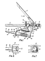
- a foot pedal controller 1 comprises a pedal 2 to which is affixed in any suitable fashion a downwardly extending lever 3.
- the lever 3 is journalled for pivotal movement in a mounting flange 4 which is fixed by screws 5 upon a support structure 6.
- Any suitable bearing means 7 may be utilized to journal the lever 3 for its pivotal movement, that shown comprising a pair of half cylindrical bearing members of a plastics material through which the lever 3 extends and which are rotatably mounted between an upper curved bearing region 8 of the mounting flange 4 and a downwardly curved bearing region 9 of an anchor plate 10 which is fastened as by screws 11 to the underside of the mounting flange thereby to be positioned below the support structure 6.
- the lever 3 is U-shaped in cross-section with flanges 12 extending from opposite ends of its web 13. Pivotal motion of the lever 3 in an anti-clockwise direction as viewed in Figure 1 caused by downward force being applied to the pedal 2 is resisted by a tension spring 14.
- the opposite ends of the spring 14 are anchored respectively to an inward lug 15 on the anchor plate 10 and one of the flanges 12 of the lever 3.
- the downward limit of travel of the pedal 2 is set by an adjustable stop taking the form of a bolt 16 which is screwed into the mounting flange 4 and fixed in its adjusted position by a lock nut 17.
- a flexible cable 18 is fitted to the foot pedal controller 1 to transmit pivotal motion of the lever 3 to a controlled member (not shown) which may take any of a number of different forms and serve any of a number of different functions.
- the present invention is particularly concerned with such fitment, ensuring same in a simple yet positive manner and without the need for any special tools.
- the cable 18 has a translatable core 19 slidable within a casing 20.
- the core 19 is operatively attached to the lever 3, and the casing 20 is restrained against motion relative to the anchor plate 10 which, as said, is fixed via the mounting flange 4 to the support structure 6.
- the attachment of the core 19 to the lever 3 will first be described and, thereafter, the securement of the casing 20 to the anchor plate 10.
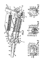
- the end of the core 19 is affixed to a lug 21 having an enlarged part-spherical head 22 from which extends an axial spigot 23 with diametrical opposite flats 24 formed by curved ends 25, i.e. of generally rectangular form.
- a retaining clip 26 of a resilient material, preferably a plastics material, is mounted about the lug 21 and is resiliently clipped to the lever 3 by which to attach the cable core 19 to the lever.
- the retaining clip 26 has a central boss 27 from which radially extend a pair of arms 28 which are turned in an axial direction away from the head 22 of the lug 21.
- the inward end of each arm is fashioned with a nib 29 turned towards the spigot 23 of the lug.
- Each nib 29 has an angled end 30 and a flat inward radial shoulder 31.
- Each arm 28 is arranged to fit around the web 13 of the lever 3 and the respective lever flange 12 with the nib shoulder 31 abutting the end edge of the flange.
- the arms 28 are radially deformable so that they may first be sprung outwardly when the clip 26 is pushed on to the lever web 13, the angled end 30 assisting the passage of the clip, and will then snap inwardly to engage the nibs 29 behind the associated flange end edge thereby to firmly retain the retaining clip 26 to the lever 3.
- the clip boss 27 is countersunk at 32 and also includes a rearward boss 33 which is apertured at 34.
- the core lug head 22 is arranged to seat in the countersunk region 32 with its spigot 23 extending through the boss aperture 34.
- the aperture 34 is configured similarly, although of larger dimensions, to the cross-section of the spigot 23.
- the external configuration of the rearward boss 33 is similarly fashioned, so as to present an external hollow wall 34 ⁇ which is generally rectangular with rounded ends.
- An axial guide lug 35 is moulded upon the retaining clip 26 at its lower region to extend the axial length thereof across the central boss 27, between the lower end of the arms 28 and across the rounded lower end of the rearward boss 33.
- the lower end of the lever 3 has its web 13 formed with a positioning aperture 36 extending lengthwise of the lever and configured complementary to the periphery of the hollow wall 34 ⁇ of the retaining clip 26. Moreover, the lever web 13 has a slot 37 extending from its positioning aperture 36 to its lowermost end to accommodate the axial guide lug 35 on the retaining clip 26.
- the core is first passed through a rearward region of the anchor plate 10 as will be described and then through the slot 37 and the positioning aperture 36 in the lever web 13, with the retaining clip 26 and the core lug 21 positioned forwardly of the lever.
- the clip wall 34 ⁇ and its guide lug 35 will engage in the positioning aperture 36 and the slot 37, respectively, in the lever web 13, thereby locating and preventing the retaining clip 26 from being slid downwardly off the end of the lever 3.
- the provision of the guide lug 35 on the retaining clip 26 also enables the clip to be properly aligned with the lever 3 so that when pushed on to the lever, an enlarged head region 27 ⁇ of the boss 22 will be uppermost and abut the lever web 13.
- the cable casing 20 is secured to the anchor plate 10 by means of a cable hub 38 having a stem 39 embraced by a metal sleeve (not shown) and crimped thereat on to the casing.
- the front end of the stem 39 is integral with a generally square cross-section flange 40.
- a forward seating flange 41 of similar cross-section but of smaller dimensions is integral with the flange 40.
- Extending forwardly of the seating flange 41 is a tubular stem 42 having a central aperture 43 therein through which the cable core 19 passes.
- the aperture 43 is flared outwardly towards the front end of the cable hub 38.
- the outer periphery of the cable hub front end is fashioned with an annular recess 44 and rearwardly thereof the cable hub 38 is provided with a pair of opposed resiliently deformable arms or wings 45 which are generally square in plan view and which extend rearwardly and radially outwardly, terminating just short of the seating flange 41 and extending slightly radially outwardly thereof.
- the anchor plate 10 has a rear wall 46 with a generally square cut-out 47 therein through which the cable core 19 is passed during its assembly to the lever 3.
- the dimensions of the cut-out 47 are complementary to those of the periphery of the seating flange 41 of the cable hub 38.
- the thickness of the anchor plate wall 46 is generally equal to the axial spacing between the cable hub flange 40 and the rearward termination of the wings 45.
- the wings 45 will resiliently deform inwardly upon engaging the cut-out edges until the seating flange 41 of the cable hub is engaged in the cut-out when the wings will spring radially outwardly to snap against the inside face of the wall 46, which will be sandwiched between those wings and the cable hub flange 40, by which the cable hub is detachably secured to the anchor plate.
- a gaiter or bellows seal 48 may be provided around the cable core 19, seating at one end in the annular recess 44 in the cable hub 38 and at its opposite end either around the core to abut the spigot 23 to the core lug 21 or around the spigot itself.
- the cable 18 is a pull cable, i.e. is core 19 transmits load only in the tensile mode.
- the reaction force on the casing 20 is in the compression mode.
- the tensile load on the core 19 is not taken by the nibs 29 of the resilient arms 28 of the retaining clip 26 but, rather, by the abutment of the enlarged head 27 ⁇ of the clip boss 22 against the lever web 13 together with the abutment of the radial root areas of the arms with the lever web.
- the reaction compression force on the cable hub 38 is not imparted to the resilient wings 45 of the hub but, instead, to the abutment of the hub flange 40 with the anchor plate wall 46.
- the cable 18 is provided complete, or integral with, the retaining clip 26 and cable hub 38 by which to attach its core 19 and hub 38 to a movable operator (or operated) member and reaction, stationary structure, respectively, so that there are no separate loose piece connector parts and, moreover, assembly is obtained merely by the application of manual forces requiring no special tools.
- the cable hub 38 could conveniently be push-fitted first into the receiving cut-out 47 in the anchor plate wall 46 and the retaining clip 26 then sprung on to the lever 3.
- the cable hub 38 is a one-piece moulding of a plastics material as also is the retaining clip 26.
- the described and illustrated foot pedal controller 1 could be used in combination with a hand control (not shown) by which the cable 18 is operable either by foot pressure or by hand.
- the lug 21 is omitted and the cable core 19 is continued through the clip aperture 34 and extended to the station at which hand control is to be exerted and there secured to a hand operator such as a knob.
- a second cable casing is provided through which that cable core extension passes, one end of that casing seating in the countersink 32 of the clip boss 27.
- the knob when hand control is to be applied, the knob is operated to exert a pull force upon the cable core extension to translate the core within its casing and so operate a controlled member (not shown). It is to be noted that such operation of the cable will have no effect upon the lever 3 affixed to the pedal 1, the core simply translating through the clip 26 without exerting any force via the clip on the pedal lever.
Landscapes
- Engineering & Computer Science (AREA)
- General Engineering & Computer Science (AREA)
- Health & Medical Sciences (AREA)
- Oral & Maxillofacial Surgery (AREA)
- Mechanical Engineering (AREA)
- Physics & Mathematics (AREA)
- General Physics & Mathematics (AREA)
- Automation & Control Theory (AREA)
- Flexible Shafts (AREA)
- Mechanical Control Devices (AREA)
Applications Claiming Priority (2)
| Application Number | Priority Date | Filing Date | Title |
|---|---|---|---|
| GB878708166A GB8708166D0 (en) | 1987-04-06 | 1987-04-06 | Remote control mechanisms |
| GB8708166 | 1987-04-06 |
Publications (2)
| Publication Number | Publication Date |
|---|---|
| EP0286262A2 true EP0286262A2 (fr) | 1988-10-12 |
| EP0286262A3 EP0286262A3 (fr) | 1989-03-01 |
Family
ID=10615307
Family Applications (1)
| Application Number | Title | Priority Date | Filing Date |
|---|---|---|---|
| EP88302471A Ceased EP0286262A3 (fr) | 1987-04-06 | 1988-03-22 | Dispositif de télécommande |
Country Status (7)
| Country | Link |
|---|---|
| US (1) | US4889005A (fr) |
| EP (1) | EP0286262A3 (fr) |
| JP (1) | JPS63266510A (fr) |
| AU (1) | AU1413688A (fr) |
| GB (2) | GB8708166D0 (fr) |
| IE (1) | IE60683B1 (fr) |
| PT (1) | PT87161A (fr) |
Cited By (2)
| Publication number | Priority date | Publication date | Assignee | Title |
|---|---|---|---|---|
| FR2659708A1 (fr) * | 1990-03-13 | 1991-09-20 | Teves Gmbh Alfred | Dispositif de fixation detachable d'un cable de traction de frein. |
| FR2990391A1 (fr) * | 2012-05-14 | 2013-11-15 | Faurecia Sieges Automobile | Systeme de fixation d'un cable sur une armature de siege de vehicule automobile, dispositif de fixation d'un tel systeme et procede de montage |
Families Citing this family (18)
| Publication number | Priority date | Publication date | Assignee | Title |
|---|---|---|---|---|
| GB8707998D0 (en) * | 1987-04-03 | 1987-05-07 | Morse Controls | Remote control mechanisms |
| AU663016B2 (en) * | 1992-11-30 | 1995-09-21 | E.P. Stelling | Bowden cable push button actuator |
| US5809840A (en) * | 1995-02-14 | 1998-09-22 | Shimano, Inc. | Protective cap system for bicycle cable |
| US5765446A (en) * | 1995-07-11 | 1998-06-16 | Sram Corporation | Control cable preload and sealing apparatus and system |
| US5630338A (en) * | 1995-07-11 | 1997-05-20 | Sram Corporation | Bicycle derailleur cable preload and sealing system |
| US5765447A (en) * | 1996-03-29 | 1998-06-16 | W. L. Gore & Associates, Inc. | Mechanical cable system having a bellows seal |
| SE518099C2 (sv) | 1997-11-21 | 2002-08-27 | Claes Johansson Automotive Ab | Inställbart pedalställ för ett fordon |
| GB9819666D0 (en) | 1998-09-09 | 1998-11-04 | Univ Aberdeen | Biosensor |
| US6349614B1 (en) * | 1998-11-06 | 2002-02-26 | Shimano, Inc. | Bicycle cable connector for splicing two cables in series |
| US6164154A (en) * | 1999-06-17 | 2000-12-26 | Teleflex Incorporated | Adjustable pedal with cable assembly |
| US6209417B1 (en) * | 1999-06-17 | 2001-04-03 | Teleflex, Incorporated | Adjustable pedal with constant ratio cable assembly |
| JP3946535B2 (ja) * | 2002-02-18 | 2007-07-18 | 株式会社大井製作所 | ドアロック装置における操作力伝達部材 |
| DE10227873A1 (de) * | 2002-06-22 | 2004-01-08 | Bayerische Motoren Werke Ag | Bowdenzug mit einem gekrümmten Führungsteil |
| JP4526779B2 (ja) * | 2003-04-22 | 2010-08-18 | 株式会社大井製作所 | アウタチューブの取付構造 |
| JP2005145125A (ja) * | 2003-11-12 | 2005-06-09 | Shimano Inc | 自転車ケーブル用シール具 |
| CN106285242B (zh) * | 2015-06-01 | 2019-04-02 | 开开特股份公司 | 用作机动车中功能单元的执行器的鲍登拉索 |
| US10252614B2 (en) * | 2017-01-27 | 2019-04-09 | Deere & Company | Utility vehicle throttle pedal |
| US12371929B2 (en) * | 2023-03-08 | 2025-07-29 | Kiekert Ag | Securing arrangement on a motor vehicle door |
Family Cites Families (29)
| Publication number | Priority date | Publication date | Assignee | Title |
|---|---|---|---|---|
| US1487266A (en) * | 1921-10-25 | 1924-03-18 | Anderson Endebrock Company Inc | Trailer brake |
| US1628858A (en) * | 1924-04-21 | 1927-05-17 | Westinghouse Electric & Mfg Co | Resistor-supporting means |
| US2009206A (en) * | 1929-03-18 | 1935-07-23 | Bendix Brake Co | Metal working process |
| FR688182A (fr) * | 1930-01-14 | 1930-08-20 | Perfectionnements aux pédales servant à la conduite des automobiles | |
| US2845812A (en) * | 1953-01-26 | 1958-08-05 | American Motors Corp | Hand brake cable assembly |
| FR1111742A (fr) * | 1954-09-27 | 1956-03-05 | Rivet élastique à expansion | |
| GB1062974A (en) * | 1964-06-18 | 1967-03-22 | Ft Products Ltd | An assembly of a cable fastened to a support and a fastener therefor |
| US3366356A (en) * | 1966-04-29 | 1968-01-30 | Illinois Tool Works | Bushing and combination of bushing and support plate |
| US3427894A (en) * | 1966-12-08 | 1969-02-18 | Teleflex Inc | Remote control assembly |
| GB1259115A (fr) * | 1968-04-29 | 1972-01-05 | ||
| GB1235447A (en) * | 1970-04-11 | 1971-06-16 | Ford Motor Co | Device for connecting a cable to a lever |
| US3645150A (en) * | 1970-07-27 | 1972-02-29 | Ford Motor Co | Adjustable cable assembly |
| US3752008A (en) * | 1971-08-31 | 1973-08-14 | Gen Motors Corp | Cable length adjuster |
| US4185515A (en) * | 1974-10-11 | 1980-01-29 | Teleflex Incorporated | Motion transmitting remote control assembly |
| US4094013A (en) * | 1975-05-22 | 1978-06-06 | U.S. Philips Corporation | Optical storage disk system with disk track guide sectors |
| FR2360785A1 (fr) * | 1976-08-05 | 1978-03-03 | Tissmetal Lionel Dupont | Dispositif de commande a distance a cable coulissant dans une gaine |
| US4064767A (en) * | 1976-11-08 | 1977-12-27 | Fiat-Allis Construction Machinery, Inc. | Control lever assembly |
| JPS5747472Y2 (fr) * | 1978-02-02 | 1982-10-19 | ||
| US4304148A (en) * | 1979-06-22 | 1981-12-08 | Illinois Tool Works Inc. | Cable fastener assembly and method of manufacture |
| JPS5644955U (fr) * | 1979-09-17 | 1981-04-22 | ||
| US4380178A (en) * | 1980-07-21 | 1983-04-19 | Teleflex Incorporated | Remote control assembly (swivel insert) |
| US4351198A (en) * | 1980-09-12 | 1982-09-28 | Allis-Chalmers Corporation | Hand and foot controlled throttle |
| FR2521659B1 (fr) * | 1982-02-15 | 1985-06-21 | Dba | Dispositif de fixation sur une paroi d'une gaine flexible et procede de fixation d'une gaine au moyen d'un tel dispositif |
| JPS59125328A (ja) * | 1982-12-29 | 1984-07-19 | Elco:Kk | 燃焼制御装置 |
| US4546666A (en) * | 1984-10-09 | 1985-10-15 | Chrysler Corporation | Mounting structure for throttle control cable |
| US4625579A (en) * | 1984-11-28 | 1986-12-02 | Teleflex Incorporated | Capped core element terminal |
| US4682513A (en) * | 1985-06-24 | 1987-07-28 | Reeder Leonard J | Repair kit for detent cables |
| JPS6224018A (ja) * | 1985-07-08 | 1987-02-02 | アツコ バブコツク インコ−ポレ−テツド | コンジツトフイツチング装置 |
| US4738155A (en) * | 1986-12-15 | 1988-04-19 | Ford Motor Company | Self-centering connector for vehicle accelerator pedal mounting lever |
-
1987
- 1987-04-06 GB GB878708166A patent/GB8708166D0/en active Pending
-
1988
- 1988-03-22 GB GB8806766A patent/GB2203209B/en not_active Expired - Lifetime
- 1988-03-22 EP EP88302471A patent/EP0286262A3/fr not_active Ceased
- 1988-03-23 US US07/172,276 patent/US4889005A/en not_active Expired - Lifetime
- 1988-03-23 IE IE86688A patent/IE60683B1/en not_active IP Right Cessation
- 1988-03-30 AU AU14136/88A patent/AU1413688A/en not_active Abandoned
- 1988-04-05 PT PT87161A patent/PT87161A/pt not_active Application Discontinuation
- 1988-04-06 JP JP63084959A patent/JPS63266510A/ja active Pending
Cited By (2)
| Publication number | Priority date | Publication date | Assignee | Title |
|---|---|---|---|---|
| FR2659708A1 (fr) * | 1990-03-13 | 1991-09-20 | Teves Gmbh Alfred | Dispositif de fixation detachable d'un cable de traction de frein. |
| FR2990391A1 (fr) * | 2012-05-14 | 2013-11-15 | Faurecia Sieges Automobile | Systeme de fixation d'un cable sur une armature de siege de vehicule automobile, dispositif de fixation d'un tel systeme et procede de montage |
Also Published As
| Publication number | Publication date |
|---|---|
| GB8708166D0 (en) | 1987-05-13 |
| IE880866L (en) | 1988-10-06 |
| GB8806766D0 (en) | 1988-04-20 |
| JPS63266510A (ja) | 1988-11-02 |
| US4889005A (en) | 1989-12-26 |
| EP0286262A3 (fr) | 1989-03-01 |
| AU1413688A (en) | 1988-10-06 |
| IE60683B1 (en) | 1994-08-10 |
| PT87161A (pt) | 1989-05-12 |
| GB2203209A (en) | 1988-10-12 |
| GB2203209B (en) | 1991-01-02 |
Similar Documents
| Publication | Publication Date | Title |
|---|---|---|
| US4889005A (en) | Remote control mechanisms | |
| US4354398A (en) | Control mechanism for hydraulic locking device | |
| US4624585A (en) | Retainer bushing | |
| GB1595849A (en) | Cable anchoring assembly | |
| US6758114B2 (en) | Electronic throttle control accelerator pedal mechanism with mechanical hysteresis provider | |
| US5884531A (en) | Low lash rotating conduit end fitting for a remote control cable assembly that isolates against vibration/noise transmission | |
| JP4518950B2 (ja) | ボーデンケーブルのシース用アンカー手段 | |
| EP0699841A1 (fr) | Système de manoeuvre comprenant une commande par câble | |
| US4800774A (en) | Pedal-load lightening apparatus | |
| US4635498A (en) | Fastening device | |
| US7559714B2 (en) | Reverse clip cap terminal connector | |
| US4989698A (en) | Control device for a lockable gas spring | |
| EP0619437B1 (fr) | Dispositif d'auto-ajustement de la longueur de cables de commande | |
| US4658660A (en) | Booster mounting arrangement | |
| US4672860A (en) | Push rod to pedal arm connection | |
| KR890001824B1 (ko) | 브레이크 조작장치 | |
| US20020149222A1 (en) | Adjustable armrest for motor vehicle inside panel | |
| US4516748A (en) | Quick connect cylinder mount stucture | |
| US5934151A (en) | Vehicle push rod and pedal assembly | |
| EP0796576B1 (fr) | Dispositif mécanique de télécommande avec bouton-poussoir à profil bas | |
| EP0566213A2 (fr) | Appui-bras pirotant pour sièges de véhicules automobiles | |
| US4887481A (en) | Remote control mechanisms | |
| US3859866A (en) | Clutch actuating mechanism | |
| EP0644837B1 (fr) | Unite de commande d'un systeme de freinage hydraulique pour vehicules automobiles | |
| EP1190185B1 (fr) | Dispositif d'ancrage pour cable |
Legal Events
| Date | Code | Title | Description |
|---|---|---|---|
| PUAI | Public reference made under article 153(3) epc to a published international application that has entered the european phase |
Free format text: ORIGINAL CODE: 0009012 |
|
| AK | Designated contracting states |
Kind code of ref document: A2 Designated state(s): DE ES FR IT SE |
|
| PUAL | Search report despatched |
Free format text: ORIGINAL CODE: 0009013 |
|
| AK | Designated contracting states |
Kind code of ref document: A3 Designated state(s): DE ES FR IT SE |
|
| 17P | Request for examination filed |
Effective date: 19890704 |
|
| 17Q | First examination report despatched |
Effective date: 19900925 |
|
| STAA | Information on the status of an ep patent application or granted ep patent |
Free format text: STATUS: THE APPLICATION HAS BEEN REFUSED |
|
| 18R | Application refused |
Effective date: 19911216 |