EP0286383A2 - Système de transmission multiplex - Google Patents
Système de transmission multiplex Download PDFInfo
- Publication number
- EP0286383A2 EP0286383A2 EP88303072A EP88303072A EP0286383A2 EP 0286383 A2 EP0286383 A2 EP 0286383A2 EP 88303072 A EP88303072 A EP 88303072A EP 88303072 A EP88303072 A EP 88303072A EP 0286383 A2 EP0286383 A2 EP 0286383A2
- Authority
- EP
- European Patent Office
- Prior art keywords
- reception
- frame
- nodes
- node
- acknowledge signal
- Prior art date
- Legal status (The legal status is an assumption and is not a legal conclusion. Google has not performed a legal analysis and makes no representation as to the accuracy of the status listed.)
- Granted
Links
- 230000005540 biological transmission Effects 0.000 title claims abstract description 133
- 230000008054 signal transmission Effects 0.000 claims description 7
- 230000006870 function Effects 0.000 description 46
- 238000004891 communication Methods 0.000 description 16
- 238000010586 diagram Methods 0.000 description 12
- 238000000034 method Methods 0.000 description 9
- 238000001514 detection method Methods 0.000 description 8
- 101100172132 Mus musculus Eif3a gene Proteins 0.000 description 6
- 238000013461 design Methods 0.000 description 5
- 230000005764 inhibitory process Effects 0.000 description 4
- 238000004519 manufacturing process Methods 0.000 description 3
- 238000012986 modification Methods 0.000 description 3
- 230000004048 modification Effects 0.000 description 3
- 239000013307 optical fiber Substances 0.000 description 2
- 230000002159 abnormal effect Effects 0.000 description 1
- 230000001174 ascending effect Effects 0.000 description 1
- 238000013500 data storage Methods 0.000 description 1
- 230000001934 delay Effects 0.000 description 1
- 230000000694 effects Effects 0.000 description 1
- 238000009432 framing Methods 0.000 description 1
- 230000002401 inhibitory effect Effects 0.000 description 1
- 238000012545 processing Methods 0.000 description 1
- 230000000630 rising effect Effects 0.000 description 1
Images






Classifications
-
- H—ELECTRICITY
- H04—ELECTRIC COMMUNICATION TECHNIQUE
- H04L—TRANSMISSION OF DIGITAL INFORMATION, e.g. TELEGRAPHIC COMMUNICATION
- H04L1/00—Arrangements for detecting or preventing errors in the information received
- H04L1/12—Arrangements for detecting or preventing errors in the information received by using return channel
- H04L1/16—Arrangements for detecting or preventing errors in the information received by using return channel in which the return channel carries supervisory signals, e.g. repetition request signals
-
- H—ELECTRICITY
- H04—ELECTRIC COMMUNICATION TECHNIQUE
- H04L—TRANSMISSION OF DIGITAL INFORMATION, e.g. TELEGRAPHIC COMMUNICATION
- H04L1/00—Arrangements for detecting or preventing errors in the information received
- H04L1/12—Arrangements for detecting or preventing errors in the information received by using return channel
- H04L1/16—Arrangements for detecting or preventing errors in the information received by using return channel in which the return channel carries supervisory signals, e.g. repetition request signals
- H04L1/1607—Details of the supervisory signal
- H04L1/1664—Details of the supervisory signal the supervisory signal being transmitted together with payload signals; piggybacking
-
- H—ELECTRICITY
- H04—ELECTRIC COMMUNICATION TECHNIQUE
- H04L—TRANSMISSION OF DIGITAL INFORMATION, e.g. TELEGRAPHIC COMMUNICATION
- H04L1/00—Arrangements for detecting or preventing errors in the information received
- H04L1/0078—Avoidance of errors by organising the transmitted data in a format specifically designed to deal with errors, e.g. location
- H04L1/0083—Formatting with frames or packets; Protocol or part of protocol for error control
-
- H—ELECTRICITY
- H04—ELECTRIC COMMUNICATION TECHNIQUE
- H04L—TRANSMISSION OF DIGITAL INFORMATION, e.g. TELEGRAPHIC COMMUNICATION
- H04L12/00—Data switching networks
- H04L12/28—Data switching networks characterised by path configuration, e.g. LAN [Local Area Networks] or WAN [Wide Area Networks]
- H04L12/40—Bus networks
- H04L12/407—Bus networks with decentralised control
- H04L12/413—Bus networks with decentralised control with random access, e.g. carrier-sense multiple-access with collision detection [CSMA-CD]
- H04L12/4135—Bus networks with decentralised control with random access, e.g. carrier-sense multiple-access with collision detection [CSMA-CD] using bit-wise arbitration
-
- H—ELECTRICITY
- H04—ELECTRIC COMMUNICATION TECHNIQUE
- H04L—TRANSMISSION OF DIGITAL INFORMATION, e.g. TELEGRAPHIC COMMUNICATION
- H04L1/00—Arrangements for detecting or preventing errors in the information received
- H04L2001/0092—Error control systems characterised by the topology of the transmission link
- H04L2001/0094—Bus
-
- H—ELECTRICITY
- H04—ELECTRIC COMMUNICATION TECHNIQUE
- H04L—TRANSMISSION OF DIGITAL INFORMATION, e.g. TELEGRAPHIC COMMUNICATION
- H04L12/00—Data switching networks
- H04L12/28—Data switching networks characterised by path configuration, e.g. LAN [Local Area Networks] or WAN [Wide Area Networks]
- H04L12/40—Bus networks
- H04L2012/40267—Bus for use in transportation systems
- H04L2012/40273—Bus for use in transportation systems the transportation system being a vehicle
Definitions
- the present invention relates to a multiplex transmission system using a CSMA/CD (Carrier Sense Multiple Access/Collision Detection) transmission system.
- CSMA/CD Carrier Sense Multiple Access/Collision Detection
- this prior art system is applied to controlling the operation of head lamps, small lamps, turn-signal lamps, a horn and the like of a vehicle
- the same vehicle driving information is transferred from one of a plurality of nodes, such as a front multiplex node coupled to the head lamps, small lamps, turn-signal lamps, horns, etc. provided on the front side of the vehicle, a combination switch node provided with a number of switches to turn on or off these components, a meter node for indicating the ON/OFF states of these components, a rear multiplex node coupled to the small lamps, turn-signal lamps, etc. provided on the rear side of the vehicle, to some or all of the remaining nodes.
- sequentially transmitting the same vehicle driving information to the individual nodes provides a significantly low transmission efficiency.
- the shortcoming is prevented by providing a so-called simultaneous multi-destination transmission function to the transmission system in which a so-called global address is written in the aforementioned destination designation area of the frame to specify all of the destination nodes and the same data is simultaneously transmitted to all the destination nodes.
- a collision would occur.
- each node is provided with a collision detection function and a transmission inhibition function so that upon proper reception of the frame from the transmitting node, only the reception acknowledge signal of the destination nodes which has the highest priority, can survive to be returened to the transmitting node.
- this method can solve the above problem concerning with the transmission efficiency, it provides no means to confirm that all the nodes requiring the data have properly received, thus resulting in a low reliability. With those nodes which do not need the data, it is also necessary to discriminate whether or not they should receive the transmitted signal, thus increasing the load of a controller which controls the circuit for executing the multiplex transmission of the individual nodes.
- the second prior art system (functional message type) is also disclosed in the aforementioned article "A Proposal for a Vehicle Network Protocol Standard", in which a so-called function address is written in the destination designation area of a frame, a single function address being associated with a plurality of predetermined nodes, each reception node compares the function address of the frame sent on the transmission path from the transmitting node with a reception function address table stored in the reception node to discriminate whether or not it should receive the frame, and, if affirmative, it returns its own address as a reception acknowledge signal to the transmitting node. In this case, if a plurality of reception nodes simultaneously return their reception acknowledge signals, the aforementioned collision would occur.
- this system is also provided with the aforementioned collision detection and transmission inhibition functions as well as a reception acknowledge signal retransmission function, so that the reception nodes sequentially return their reception acknowledge signal in the order from the highest priority to the lowest one.
- the transmitting node collates the returned reception acknowledge signals with the transmission function address-physical address correlation table to discriminate if the reception acknowledge signals have properly been returned from the destination nodes specified by the function address.
- each node should store the transmission function address-physical address correlation table and the reception function address table, thus requiring a large capacity memory and a memory control circuit. This increases the manufacturing cost of the transmission system.
- a multiplex transmission system in which one of a plurality of nodes, as a transmission node, mutually coupled together through a transmission path transmits data frame by frame to at least one of other nodes as at least one reception node, and the at least one reception node returns reception acknowledge signals to the transmitting node upon proper reception of the frame of data.
- a reception acknowledge signal area including a plurality of bits is provided following the frame transmitted from the transmitting node and is divided into a plurality of bit areas respectively assigned to the plurality of nodes.
- the at least one reception node returns the reception acknowledge signal to the transmitting node from one of the respectively-assigned bit areas of the reception acknowledge signal area.
- a pulse width modulation code for discriminating a binary logic based on a size (wide or narrow) of the pulse width is used as a transmission code.
- a destination designation area having the same length as the reception acknowledge signal area may be provided in a frame and is divided into a plurality of bit areas respectively assigned with the plurality of nodes.
- the individual destination nodes are specified by the respective bit areas of the destination designation area of the frame.
- the transmitting node upon reception of the reception acknowledge signal from the at least one reception node, compares a content of the received reception acknowledge signal area with a content of the destination designation area of the frame so as to discriminate successfulness of a signal transmission.
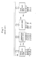
- a plurality of nodes consisting of, for example, a front multiplex node FN, a combination switch node CS, a meter node MT and a rear multiplex node RN are mutually coupled together through a multiplex bus (transmission path) MB comprising a wire or an optical fiber of the like.
- the front multiplex node FN is coupled to a front turn-right signal lamp 6, a front turn-left signal lamp 7, a front small lamp 8, a horn 9, etc.
- the combination switch node CS is coupled to a turn-right switch 10, a turn-left switch 11, a small-lamp switch 12, a horn switch 13, a head-lamp high beam switch 14, etc.
- the meter node MT is coupled to a turn-right indicator 15, a turn-left indicator 16, a head-lamp high beam indicator 17, etc.
- the rear multiplex node RN is coupled to a rear turn-right signal lamp 18, a rear turn-left signal lamp 19, a tail lamp 20 (which is turned on when the small lamp switch 12 is ON), etc.
- vehicle driving information is transmitted for each frame F, as shown in Fig. 2(a).
- the frame F has a SD (Starting Delimiter) code, a destination address, a local or source address, a data length, data 1 to data N and a check code.
- SD Startting Delimiter
- the SD code is a specific code indicating the start of the frame F, and the reception nodes acknowledge the start of the frame F upon reception of the SD code.
- 11111111 is designated as the destination address which is called the global address
- the multi-destination transmission function is often added to every node and 255 nodes can be coupled within the network at a maximum.
- the "local address" field is written with the address of that node which transmits the frame F so that another node, upon reception of this frame, can detect from which node the frame has been transmitted.
- the "data length" field is written with the number of data following this field; if there are N data, then N is written as the data length.
- the reception nodes Upon reception of the frame, the reception nodes read the data by the data length.
- the transmitted content of the frame following the data field is the check code (error detection code) which can indicate the end of the frame.
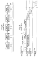
- each reception node checks whether or not the contents of the received frame are correct, and if they are correct, the reception node sends its local address onto the transmission path MB as an ACK signal A upon elapse of a Time T1 with a time T2 after completion of the frame transmission, as shown in Fig. 2(b).
- the node which has transmitted the frame F receives the ACK signal A and recognizes that the data has been properly received by the reception nodes.
- the reception node If the data is not properly received by the reception node (if a transmission error is detected by the check code) or a framing error occurs (if the length of the actually-sent data is shorter or longer than the one specified by the data length), the reception node does not return the ACK signal to the transmitting node as shown in Fig. 3(b). In this case, as shown in Fig. 3(a), if the ACK signal is not returned within a predetermined time T2 after the completion of the frame transmission, the transmitting node considers that the transmission of the frame F is unsuccessful and starts retransmitting the same frame F.
- Fig. 4 illustrates the case where one node simultaneously transmits the same frame to the other nodes.
- the transmitted frame in this case has the same structure as the one involved in frame transmission to one node, but the destination address would be the global address (11111111) so that all the nodes, except the transmitting node, coupled to the transmission path MB receive the frame of data. If all the reception nodes properly receive the data, they simultaneously return their local addresses as the ACK signals A upon elapse of a given Time T1 ( ⁇ T2) after the completion of the frame transmission, as shown in Fig. 4 (b).
- each node is provided with the collision detection function for detecting the collision for each bit and the transmission inhibition function for inhibiting the transmission of the data from the succeeding bit with respect to a signal having a low priority upon occurrence of the collision.
- the transmitting node receives the ACK signal A from those of the reception nodes whose addresses are strong enough not to be changed when colliding with an inversion signal due to the structure of the transmission path and can simply attain the acknowledgment that at least one of all the reception nodes has properly received the frame in the multi-destination transmission.
- This prior art transmission system is not, therefore, suitable in data transmission requiring a high reliability.
- the vehicle driving information may be transmitted with the frame format as shown in Fig. 6.
- the frame format in this case is the same as the one shown in Figs. 2-4; however, a functionally-given address (function address), not a physical address, is designated as a destination address and the reception nodes return the ACK signals A as shown in Figs. 6(b)-6(d) in accordance with this address.
- the function address corresponds to the functional addressing mentioned in the article "A Proposal for a Vehicle Network Protocol Standard" presented in the SAE International Congress and Exposition (February 1986).
- the function address to be transmitted from the node N1 may be determined as illustrated in the following Table 1.
- the function address 4 indicates that the nodes N2 and N4 are the destination nodes while the function address 5 indicates that the nodes N2, N4 and N5 are the destination nodes.
- the individual nodes N1-N5 have their respective correlation tables for a transmission use between the function addresses and the physical addresses (see the exemplified Table 1 for the node N1) so as to be recognizable to which physical nodes to transmit a frame of data and reception function tables (e.g., Table 2 given below for the node N4) for a reception use so as to be recognizable from which function address the frame should be received.
- Table 1 for the node N1
- Table 2 given below for the node N4
- the first three function addresses (3, 4 and 5) are to be transmitted from the node N1 and the next three function addresses (8, 11 and 14) are to be transmitted from the node N2.
- the node N1 transmits the frame F as shown in Fig. 7. And, the nodes N3 and N5 recognize that they should receive the frame F with the function address "6" based on their own reception function tables (similar to the Table 2 for the node N4).
- the nodes N3 and N5 receive the frame F and return their local addresses as the ACK signals A to the node N1 if no data error is detected by checking the check code as per the first prior art system as shown in Figs. 2-4.
- the ACK signals A in this case may simultaneously be returned from a plurality of nodes as is the case in the multi-destination transmission as shown in Fig. 4, the aforementioned problem of the first prior art system can be overcome by providing the bit-by-bit collision detection and the transmission inhibition function from the succeeding bit with respect to a low priority signal as well as an ACK signal retransmission function to each node.
- the ACK signals from the nodes which have received the frame F are aligned in accordance with the descending order from the reception node having the strongest address code to the one having the weakest address code in consideration of the transmission path structure.
- the node that has transmitted the frame F collates the returned ACK signals with the function address-physical address correlation table for transmission use such as the Table 1 to detect if the ACK signals are returned from all the nodes which should receive the frame F.
- the same frame is retransmitted in the same manner as is done in the node-to-node transmission shown in Fig. 3.
- the bus may be occupied only by the ACK signals concerning this frame. To avoid this shortcoming, therefore, the number of nodes allowed to return the ACK signals by a single function address is limited.
- the first prior art multiplex transmission system for vehicles in transmitting data from one node, it is either one or all of the remaining nodes which can be designated as the destination. If this data transmission is taken as the flow of a multiple signal in the multiplex transmission system for vehicles as shown in Fig. 1, the same signal is often transmitted from one node to a plurality of nodes as indicated by the following Table 3.
- a plurality of frames should be transmitted as shown in Fig. 9, reducing the transmission efficiency.
- Fig. 8 illustrates that the same data B is simultaneously transmitted to the nodes N3 and N5 from the node N1; in this case, the ACK signals are simultaneously returned from the nodes N3 and N5 as shown in Figs. 8(b) and 8(c). Consequently, ACK 5 having a high priority can be observed on the transmission path, as shown in Fig. 8(d).
- Fig. 9 illustrates the case where the same data B is transmitted to the nodes N3 and N5 from the node N1 and the transmission acknowledgment needs to be returned from each node. In this case, the nodes N3 and N5 return the ACK signals with the respective delays after reception of their respective frames (see Fig. 2(a)), as shown in Figs. 9(b) and 9(c).
- the second prior art system (as shown in Figs. 5-7) can solve the aforementioned problems of the first prior art system, namely, that data transmission to a plurality of arbitrary nodes is not possible and it is not possible in transmission to a plurality of nodes to attain the acknowledgment which indicates that all the nodes expected to receive the data have properly received it.
- each node should have a large memory to store the transmission function address-physical address correlation table and the reception function address table, as shown in the Tables 1 and 2, and should also have a memory control circuit. This inevitably increases the scale of the circuit necessary to realize the multiplex transmission system and hence increases the manufacturing cost of the transmission system.
- a multiplex transmission system which transmits vehicle driving information between a plurality of nodes provided in a vehicle will now be explained.
- the multiplex transmission system has the same schematic arrangement as shown in Figs. 1 and 5, and uses the CSMA/CD transmission system in which a plurality of nodes are coupled together through a bus serving as a transmission path, vehicle driving information is transmitted from any one of the nodes for each frame having a destination address and an ACK signal is returned to the sender from the node designated by the destination address when the destination node has properly received the frame.
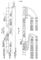
- the vehicle driving information is transmitted for each frame F having the format as shown in Fig. 10.
- the frame F includes an SD code, a destination address (16 bits), a local address, a data length, data 1 to data N and a check node.
- the SD code is a specific code indicating the start of the frame F.
- the destination address different from the one involved in the prior art systems, is designated by a value of a physical area assigned in the destination address field for each node, not by a coded value of a physical address ( or a real address), e.g., "00000010" for a real address "2" and "00000011” for a real address "3" expressed in one byte. More specifically, an address area consisting of a plurality of bits is provided in the frame F to specify the destination address and is divided into a plurality of bit areas (destination designation areas), and the divided bit areas are respectively assigned to the addresses of the nodes.
- Fig. 11 illustrates an example of a frame having such a destination address field.
- each node is assigned with one bit of the destination address field consisting of 16 bits, its bit position differing from the bit position of another node.
- these 16 bits are respectively assigned to the nodes from the first bit in the ascending order of the physical addresses of the nodes, and the nodes are designated by setting their respective bits to 1.
- the destination address having its third and firth bits from the start set to 1 and the remaining bits set to 0, i.e., 0010100000000000, needs to be transmitted.
- the destination address is normally assigned such that one bit is assigned to each node; however, as needed, a plurality of bits may be assigned to each node and/or the destination nodes may be assigned in an arbitrary order.
- the local address field through the check code field following the destination address field are the same as those used in the prior art systems.
- An ACK field has its ACK signal return areas assigned for the respectively nodes in the same order as the destination address field for use in acknowledgment of the proper reception of the frame. More specifically, the ACK signal return areas having the same length as the destination designation areas of the destination address is provided, and the ACK signal specific to each node is returned at the ACK signal return area corresponding to the destination designation area associated with this node.
- the nodes N3 and N5 if both of the nodes N3 and N5 have properly received the frame, the nodes N3 and N5 send 1 to the third and fifth bits of the ACK field, respectively, and the node N1 receives "0010100000000000" as the ACK signals A3 and A5.
- the node N1 which has transmitted the frame performs a operation as to whether or not the destination address coincides with the value of the ACK field (see the flowchart as shown in Fig. 12) in order to discriminate whether or not the desired frame F has been properly transmitted to the destination.
- the transmitting node compares the information carried by the ACK signals with the information of the destination address of the frame to discriminate the successfulness of the signal transmission.
- the reception nodes can easily get the transmission timing in the ACK field if the transmitting node transmits "1" for the portion of the phase 1 of each bit of ACK signal return areas, and the reception node counts the pulse on the transmission path in order to return the ACK signal to the transmitting node in synchronism with the rising or falling of the phase 1 output from the sender in the ACK signal return region associated with the reception node. That is, in this case, the pulse width modulation code for discriminating the binary logic (logic 1 or logic 0) based on the wideness or narrowness of the pulse width is used as the transmission code. The pulse width modulation code may be used only in the ACK field or in any field in the frame.
- the durations of the individual phases can be arbitrarily set and may of course differ from one another; however, setting these phases to have equal durations can provide the simplest circuit arrangement.
- the ACK signals can be returned from all the nodes designated as the destination, thus ensuring a sufficiently high reliability of multiplex transmission.
- each node need not store a function address-physical address correlation table so that is is unnecessary to provide a large memory or a memory control circuit. This can reduce the scale of the necessary circuit and contribute to reducing the manufacturing cost of the system.
- the phase can be set to the opposite type without problems. That is, if the destination designation areas are set to "0" to designate the destination and to "1" to designate no destination, the checking of the proper completion of the frame transmission/reception as shown in Fig. 13 can be executed by checking whether or not the value of the destination address plus the value of the ACK field in the transmitted frame becomes 0.
- 16 nodes can be coupled together at the maximum; however, an increase in the number of nodes to be coupled to the multiplex transmission path can be coped with increasing the lengths of the destination designation area and the ACK field.
- the quantity of data is variable and the data length is included in the frame.
- the quantity of data can be varied without including the data length in the frame.
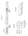
- Fig. 17 illustrates the frame format used in the above case.
- the specific code EOD End of Data
- the specific code EOD End of Data
- the reception node designated by the destination address area recognizes the end of data.
- the preceding one byte to the detection of the code EOD is an error check code (here, an 8-bit CRC), and the preceding 4 bytes to this error check code until the end of the local address can be recognized as actual data.
- a code for indicating the start of the frame need not be of a special form such as the SD code used in the first embodiment, but may be a code as shown in Fig. 19, which has a continuous high-level duration over 5 phases. All the nodes except the transmitting node can recognize the start of the frame by detecting this code.
- the local address is used as acknowledgement of the frame.
- there are 16 nodes which can be designated as the destination so that 4 bits are sufficient for recognition of the local address and this 4-bit local address plus a 4-bit priority bit may be provided preceding to the destination address area, as shown in Fig. 20.
- the addresses of the destination node and transmitting node are included in the frame as a frame identifier.
- a frame identification code having no relationship with the node address may be introduced without providing the node address in the frame and used as the priority bit for a message.
- Fig. 22 illustrates the frame format designed in the above manner, which produces the following effects.
- the "IDP" (Identification with Priority) in the format is a frame identification code and also indicates the priority of the frame.
- the reception node may decrypt the received data in such a manner that the front multiplex node and the rear multiplex node which are expected to receive the data, for example, discriminate from a frame with the local address "5,” that the j-th bit signal of the i-th byte sent from the node having the address "5" (e.g., the combination switch node) is associated with the small-lamp switch.
- the reception nodes can change the discrimination from that the j-th bit signal of the i-th byte of the data transmitted from the node with the old address "5" (the combination switch node) is associated with the small-lamp switch to that the q-th bit signal of the p-th byte of the data transmitted from the node with the address "3" (e.g., the meter node) is associated with the small-lamp switch.
- the frame format does not necessitate the above modification of the data decryption software by assigning specific frame identification codes to the individual functions in advance such that, for example, the s-th bit of the r-th byte of the frame having the frame identification code 11 indicates the small-lamp switch, even in the case where the small-lamp switch is included in the combination switch node or the meter node.
- the frame format as shown in Fig. 23 can be easily realized which has a message type identification code with priority further provided preceding to the frame identification code of the format shown in Fig. 22.
- the message type identification code with priority may be constituted by a 5-bit priority bit and a 3-bit message type identification code. The greater the priority number, the higher the priority given at the time of collision. The use of the message type identification code ensures that various message type can be used when desired.
- Each multiplex node ND has the circuit arrangement as shown in Fig. 25, in which detection signals of various sensors in the vehicle and ON/OFF signals of the switches are input to an input circuit 10 and the different input signals are supplied to a central processing unit (CPU) 12.
- the CPU 12 performs an arithmetic operation on the input signals as needed and sends the signals, which need to be transmitted to a communication controller 14, in the form of data in the aforementioned frame.
- the communication controller 14 produces an error check code and affixes it to the data, and further affixes a start bit and an EOD to the resultant data, thus preparing the final form as a frame.
- the communication controller 14 executes a coding operation (PWM) coding, etc.) on the frame as needed and sends the frame F onto the multiplex transmission path MS.
- PWM coding operation
- the communication controller 14 completes the data transmission.
- the communication controller 14 considers that some of the reception nodes have not properly received the frame and repeats the transmission of the frame.
- the communication controller 14 considers that the associated node is abnormal and stops the frame retransmission, thus preventing the multiplex transmission path MB from being full of signals.
- the communication controller 14 in each of the reception multiplex nodes receives the frame F transmitted on the multiplex transmission path MB, decodes it as needed, checks the received data by means of the error check code, etc., and sends bit "1" in the associated ACK signal return area following the frame at a specific timing if no error is detected. If a data error occurs, bit "1" is not set in the associated ACK signal return area.
- the following two methods may be used to determine the reception or disregarding of the received frame.
- the first method permits the communication controller 14 to make the decision.
- the communication controller 14 has a reception IDP code table, and discriminates that the received frame is necessary for the associated node when the IDP code included in the frame coincides with the one listed in its own reception IDP code table, and supplies the data of the frame to the CPU 12.
- the communication controller 14 does not supply the data of the frame even though the associated node returns the ACK signal. In this case, since the CPU 12 is in no way initiated in determining the necessity of the received frame, the load of the CPU 12 can be reduced.
- the reception IDP code table provided in communication controller 14 corresponds to the aforementioned reception function table used in the second prior art system
- the ACK signal is returned for every frame in the transmission system according to this embodiment, unlike in the case of the second prior art system. Therefore, the transmitting node discriminates that the signal transmission is successful if the ACK signals are returned from all the nodes coupled to the network, except itself. This can eliminate the need to provide a table corresponding to the function address-physical address correlation table used in the second prior art system, thus requiring a small memory capacity in the communication controller 14.
- the second method permits the CPU 12 to make the decision regarding the necessity of the received frame.
- all the data received by the communication controller 14 is supplied to the CPU 12 which checks the IDP code to select the necessary data and abandon the unnecessary one.
- the second method can be realized in terms of software without modifying the programs executed by the CPU 12.
- the second method increases the frequency of the data transmission to the CPU 12 from the communication controller 14, the communication controller 14 can be realized with a smaller scale as compared with the one involved in the prior art systems. More specifically, the second method eliminates the need to use a memory corresponding to the function address-physical address correlation table and the reception function table which are used in the second prior art system, thus reducing the scale of the communication controller.
- the data selected by either one of the above methods is compared and processed, as needed, with another signal in the CPU 12 to produce control signals for driving a predetermined actuator and the like in the vehicle and the control signals are supplied to an output circuit 16 to drive the target actuator and the like.
- this system can execute the transmission of the necessary data between the individual nodes, irrespective of the node address or the location information. Even if a change is made to a signal to be transmitted from the transmitting node or to a signal to be received by the reception nodes, therefore, it is unnecessary to modify the destination on the reception side or the transmission side for every change. This provides easy means to deal with a possible design modification.
- Fig. 24 illustrates a modification of the frame structure of Fig. 23 in which the data length is variable.
Landscapes
- Engineering & Computer Science (AREA)
- Computer Networks & Wireless Communication (AREA)
- Signal Processing (AREA)
- Small-Scale Networks (AREA)
- Detection And Prevention Of Errors In Transmission (AREA)
Applications Claiming Priority (2)
| Application Number | Priority Date | Filing Date | Title |
|---|---|---|---|
| JP62084136A JPH0771088B2 (ja) | 1987-04-06 | 1987-04-06 | 多重伝送方式 |
| JP84136/87 | 1987-04-06 |
Publications (3)
| Publication Number | Publication Date |
|---|---|
| EP0286383A2 true EP0286383A2 (fr) | 1988-10-12 |
| EP0286383A3 EP0286383A3 (en) | 1990-05-23 |
| EP0286383B1 EP0286383B1 (fr) | 1995-03-15 |
Family
ID=13822079
Family Applications (1)
| Application Number | Title | Priority Date | Filing Date |
|---|---|---|---|
| EP88303072A Expired - Lifetime EP0286383B1 (fr) | 1987-04-06 | 1988-04-06 | Système de transmission multiplex |
Country Status (6)
| Country | Link |
|---|---|
| US (1) | US4914654A (fr) |
| EP (1) | EP0286383B1 (fr) |
| JP (1) | JPH0771088B2 (fr) |
| KR (1) | KR960015858B1 (fr) |
| CA (1) | CA1283228C (fr) |
| DE (1) | DE3853310T2 (fr) |
Cited By (11)
| Publication number | Priority date | Publication date | Assignee | Title |
|---|---|---|---|---|
| EP0330223A3 (en) * | 1988-02-25 | 1990-05-09 | Fujitsu Limited | Information distribution system |
| EP0319271A3 (en) * | 1987-11-30 | 1990-12-05 | The Furukawa Electric Co., Ltd. | Multiplex transmission system |
| EP0399491A3 (fr) * | 1989-05-22 | 1993-05-12 | Mazda Motor Corporation | Système de transmission multiplex pour utilisation dans un véhicule |
| EP0507579A3 (fr) * | 1991-04-02 | 1994-03-02 | Furukawa Electric Co Ltd | |
| US5577024A (en) * | 1993-07-08 | 1996-11-19 | Nokia Mobile Phones Ltd. | Multiple access radio system |
| EP0862296A3 (fr) * | 1997-02-21 | 2000-01-05 | Denso Corporation | Système de communication de données et unité de contrôle électronique utilisée dans celui-ci |
| WO2013130837A1 (fr) * | 2012-02-29 | 2013-09-06 | Qualcomm Incorporated | Appareil et procédés pour la compression d'accusés de réception en blocs |
| US8832515B2 (en) | 2012-02-29 | 2014-09-09 | Qualcomm Incorporated | Block acknowledgement mechanism including sequence number acknowledgement and retry bit |
| US9253290B2 (en) | 2012-02-29 | 2016-02-02 | Qualcomm Incorporated | Apparatus and methods for block acknowledgment compression |
| US9363707B2 (en) | 2011-12-29 | 2016-06-07 | Qualcomm Incorporated | Systems and methods for generating and decoding short control frames in wireless communications |
| US9781627B2 (en) | 2013-04-08 | 2017-10-03 | Qualcomm Incorporated | Systems and methods for generating and decoding short control frames in wireless communications |
Families Citing this family (38)
| Publication number | Priority date | Publication date | Assignee | Title |
|---|---|---|---|---|
| EP0367830A4 (en) * | 1988-02-29 | 1993-04-07 | Kabushiki Kaisha Komatsu Seisakusho | Series control unit and method of control |
| US5289465A (en) * | 1988-08-18 | 1994-02-22 | Bull S.A. | Method for data transmission over an internal bus of a workstation apparatus with an internal bus for implementing the method, and an adapter circuit for the internal bus |
| JP2771556B2 (ja) * | 1988-10-31 | 1998-07-02 | 古河電気工業株式会社 | 車両用多重伝送装置 |
| GB8916489D0 (en) * | 1989-07-19 | 1989-09-06 | British Telecomm | Data communication method and system |
| US4991171A (en) * | 1989-09-26 | 1991-02-05 | At&T Bell Laboratories | Broadcast packet switch network |
| US5329525A (en) * | 1989-10-23 | 1994-07-12 | Nissan Motor Company, Limited | System and method applicable to automotive vehicles utilizing time division multiplex mode for communicating data between master and slave stations |
| US5128945A (en) * | 1989-12-21 | 1992-07-07 | Stratacom, Inc. | Packet framing using cyclic redundancy checking |
| US5072449A (en) * | 1989-12-21 | 1991-12-10 | Stratacom, Inc. | Packet framing using cyclic redundancy checking |
| US5510775A (en) * | 1990-03-07 | 1996-04-23 | Siemens Aktiengesellschaft | Method of personalizing an electronic module and electronic circuit and module for implementing the method |
| US5388109A (en) * | 1990-04-26 | 1995-02-07 | Universal Data Systems, Inc. | Data communications device with resident link adapter |
| US5343469A (en) * | 1990-06-14 | 1994-08-30 | Nec Corporation | Communication system and communication devices having lock function |
| US6108755A (en) * | 1990-09-18 | 2000-08-22 | Fujitsu Limited | Asynchronous access system to a shared storage |
| EP0809185B1 (fr) * | 1990-09-18 | 1999-12-08 | Fujitsu Limited | Méthode de duplication de mémoire partagée |
| GB2252020A (en) * | 1990-12-04 | 1992-07-22 | Ibm | Flow control in data communication systems. |
| JP2857501B2 (ja) * | 1991-02-18 | 1999-02-17 | マツダ株式会社 | 多重伝送装置 |
| KR100201580B1 (ko) * | 1991-04-02 | 1999-06-15 | 후루까와 준노스께 | 다중전송시스템 |
| JPH04305754A (ja) * | 1991-04-02 | 1992-10-28 | Furukawa Electric Co Ltd:The | 多重伝送方式 |
| US5652840A (en) * | 1991-10-08 | 1997-07-29 | Mitsubishi Denki Kabushiki Kaisha | Communication control apparatus for a small-scale network |
| JP2755062B2 (ja) * | 1992-09-08 | 1998-05-20 | 住友電気工業株式会社 | 光通信システム |
| DE69433098T2 (de) * | 1993-02-15 | 2004-03-25 | Honda Giken Kogyo K.K. | Vorrichtung zur Übertragung von Daten |
| EP0625751A1 (fr) * | 1993-05-14 | 1994-11-23 | Siemens Aktiengesellschaft | Procédé de transmission d'information de façon sûre sur un bus |
| JPH06324928A (ja) * | 1993-05-14 | 1994-11-25 | Mitsubishi Electric Corp | ログ生成装置とファイルの異なるバージョンの調停のための装置及び異なる場所にあるコンピュータファイルの異なるバージョンを調停するための装置 |
| JP2806466B2 (ja) * | 1993-05-17 | 1998-09-30 | 株式会社日立製作所 | データ伝送制御方法 |
| US5517507A (en) * | 1993-12-03 | 1996-05-14 | Motorola, Inc. | Notification by energy burst of messages with unacceptable quality |
| JP3200293B2 (ja) * | 1994-08-08 | 2001-08-20 | 松下電器産業株式会社 | リング型lanにおける同報通信方法 |
| US5715164A (en) * | 1994-12-14 | 1998-02-03 | Ascom Hasler Mailing Systems Ag | System and method for communications with postage meters |
| US5579299A (en) * | 1994-12-16 | 1996-11-26 | Chrysler Corporation | Communications network, a dual mode data transfer system therefor |
| US6873627B1 (en) * | 1995-01-19 | 2005-03-29 | The Fantastic Corporation | System and method for sending packets over a computer network |
| US6625652B1 (en) | 1995-01-19 | 2003-09-23 | The Fantastic Corporation | System and method for host list pruning |
| US6453438B1 (en) | 1995-01-19 | 2002-09-17 | The Fantastic Corporation | System and method for automatically rescheduling a data transmission to members of a group |
| US5553083B1 (en) * | 1995-01-19 | 2000-05-16 | Starburst Comm Corp | Method for quickly and reliably transmitting frames of data over communications links |
| DE19612631A1 (de) * | 1995-03-31 | 1996-10-02 | Mazda Motor | Multiplexdatenübermittlungssystem |
| US5668810A (en) * | 1995-04-26 | 1997-09-16 | Scientific-Atlanta, Inc. | Data transmission protocol method and apparatus |
| US6289012B1 (en) | 1998-08-03 | 2001-09-11 | Instanton Corporation | High concurrency data download apparatus and method |
| US7009969B1 (en) * | 1999-06-08 | 2006-03-07 | Cisco Technology, Inc. | Local area network and message packet for a telecommunications device |
| DE102004009889A1 (de) * | 2003-02-27 | 2004-09-16 | Oasis Silicon Systems Ag | Synchrone Multi-Cluster Netzwerkarchitektur |
| US7546508B2 (en) * | 2003-12-19 | 2009-06-09 | Nokia Corporation | Codec-assisted capacity enhancement of wireless VoIP |
| US10511521B2 (en) * | 2016-08-03 | 2019-12-17 | Anchorfree Inc. | System and method for virtual multipath data transport |
Family Cites Families (12)
| Publication number | Priority date | Publication date | Assignee | Title |
|---|---|---|---|---|
| US3676846A (en) * | 1968-10-08 | 1972-07-11 | Call A Computer Inc | Message buffering communication system |
| JPS5247601A (en) * | 1975-10-15 | 1977-04-15 | Hitachi Ltd | Polling method of maultipoint system |
| JPS54148403A (en) * | 1978-05-15 | 1979-11-20 | Nec Corp | Polling system |
| US4379946A (en) * | 1980-06-05 | 1983-04-12 | Nippon Telegraph & Telephone Public Corporation | Signalling system and signal control equipment for multi-address calling |
| JPS59122256A (ja) * | 1982-12-28 | 1984-07-14 | Fuji Electric Co Ltd | 割込方式 |
| US4577308A (en) * | 1984-04-06 | 1986-03-18 | At&T Bell Laboratories | Multiplexed interconnection of packet switching node packages |
| FR2575881B1 (fr) * | 1985-01-08 | 1994-02-18 | Bull Sems | Procede d'echange de messages dans un reseau en anneau et dispositif permettant la mise en oeuvre du procede |
| JPS61214835A (ja) * | 1985-03-20 | 1986-09-24 | Sanyo Electric Co Ltd | グル−プ別同報通信方式 |
| JPS6224741A (ja) * | 1985-07-25 | 1987-02-02 | Matsushita Electric Works Ltd | 多重伝送方式 |
| US4715031A (en) * | 1985-09-23 | 1987-12-22 | Ford Motor Company | Vehicular data transfer communication system |
| US4719458A (en) * | 1986-02-24 | 1988-01-12 | Chrysler Motors Corporation | Method of data arbitration and collision detection in a data bus |
| US4706082A (en) * | 1986-02-24 | 1987-11-10 | Chrysler Motors Corporation | Serial data bus for intermodule data communications |
-
1987
- 1987-04-06 JP JP62084136A patent/JPH0771088B2/ja not_active Expired - Fee Related
-
1988
- 1988-04-04 US US07/177,497 patent/US4914654A/en not_active Expired - Fee Related
- 1988-04-05 CA CA000563236A patent/CA1283228C/fr not_active Expired - Fee Related
- 1988-04-06 EP EP88303072A patent/EP0286383B1/fr not_active Expired - Lifetime
- 1988-04-06 KR KR1019880003855A patent/KR960015858B1/ko not_active Expired - Lifetime
- 1988-04-06 DE DE3853310T patent/DE3853310T2/de not_active Expired - Fee Related
Cited By (19)
| Publication number | Priority date | Publication date | Assignee | Title |
|---|---|---|---|---|
| EP0319271A3 (en) * | 1987-11-30 | 1990-12-05 | The Furukawa Electric Co., Ltd. | Multiplex transmission system |
| EP0330223A3 (en) * | 1988-02-25 | 1990-05-09 | Fujitsu Limited | Information distribution system |
| EP0399491A3 (fr) * | 1989-05-22 | 1993-05-12 | Mazda Motor Corporation | Système de transmission multiplex pour utilisation dans un véhicule |
| EP0507579A3 (fr) * | 1991-04-02 | 1994-03-02 | Furukawa Electric Co Ltd | |
| US5357525A (en) * | 1991-04-02 | 1994-10-18 | The Furukawa Electric Co., Ltd. | Multiplex transmission system |
| EP0851623A3 (fr) * | 1991-04-02 | 1999-07-21 | The Furukawa Electric Co., Ltd. | Système de transmission multiplexé |
| US5577024A (en) * | 1993-07-08 | 1996-11-19 | Nokia Mobile Phones Ltd. | Multiple access radio system |
| US6167057A (en) * | 1997-02-21 | 2000-12-26 | Denso Corporation | Data communication system and electronic control unit used therein |
| EP0862296A3 (fr) * | 1997-02-21 | 2000-01-05 | Denso Corporation | Système de communication de données et unité de contrôle électronique utilisée dans celui-ci |
| US9363707B2 (en) | 2011-12-29 | 2016-06-07 | Qualcomm Incorporated | Systems and methods for generating and decoding short control frames in wireless communications |
| WO2013130837A1 (fr) * | 2012-02-29 | 2013-09-06 | Qualcomm Incorporated | Appareil et procédés pour la compression d'accusés de réception en blocs |
| US8832515B2 (en) | 2012-02-29 | 2014-09-09 | Qualcomm Incorporated | Block acknowledgement mechanism including sequence number acknowledgement and retry bit |
| CN104137458A (zh) * | 2012-02-29 | 2014-11-05 | 高通股份有限公司 | 用于块确收压缩的装置和方法 |
| US9019822B2 (en) | 2012-02-29 | 2015-04-28 | Qualcomm Incorporated | Apparatus and methods for block acknowledgment compression |
| US9253290B2 (en) | 2012-02-29 | 2016-02-02 | Qualcomm Incorporated | Apparatus and methods for block acknowledgment compression |
| US9301196B2 (en) | 2012-02-29 | 2016-03-29 | Qualcomm Incorporated | Apparatus and methods for block acknowledgment compression |
| US9432879B2 (en) | 2012-02-29 | 2016-08-30 | Qualcomm Incorporated | Apparatus and methods for block acknowledgment compression |
| CN104137458B (zh) * | 2012-02-29 | 2017-10-24 | 高通股份有限公司 | 用于块确收压缩的装置和方法 |
| US9781627B2 (en) | 2013-04-08 | 2017-10-03 | Qualcomm Incorporated | Systems and methods for generating and decoding short control frames in wireless communications |
Also Published As
| Publication number | Publication date |
|---|---|
| KR960015858B1 (ko) | 1996-11-22 |
| EP0286383B1 (fr) | 1995-03-15 |
| DE3853310D1 (de) | 1995-04-20 |
| CA1283228C (fr) | 1991-04-16 |
| JPS6427338A (en) | 1989-01-30 |
| DE3853310T2 (de) | 1995-11-16 |
| KR880013337A (ko) | 1988-11-30 |
| JPH0771088B2 (ja) | 1995-07-31 |
| US4914654A (en) | 1990-04-03 |
| EP0286383A3 (en) | 1990-05-23 |
Similar Documents
| Publication | Publication Date | Title |
|---|---|---|
| EP0286383B1 (fr) | Système de transmission multiplex | |
| US4951281A (en) | Multiplex transmission system | |
| US5499247A (en) | Multiplex transmission system having plurality of nodes and common transmission line and using divided data areas | |
| EP0217571B1 (fr) | Système de communication pour le transfert de données | |
| EP0507581B1 (fr) | Système de transmission à multiplexage | |
| FI97841C (fi) | Tiedonsiirtoväyläjärjestelmä ja asema käytettäväksi tällaisessa tiedonsiirtoväyläjärjestelmässä | |
| US6901469B2 (en) | Communication control apparatus using CAN protocol | |
| EP0866401B1 (fr) | Système d'identification des informations pour identifier des répondeurs | |
| KR100336067B1 (ko) | 다중전송장치 | |
| KR960009471B1 (ko) | 다중전송방법 | |
| JPH0828725B2 (ja) | 多重伝送方式 | |
| US5272699A (en) | Method of multiplex transmission | |
| JPH01143537A (ja) | 多重伝送方式 | |
| JPH0457140B2 (fr) | ||
| JP2539490B2 (ja) | 車載用デ―タ伝送プロトコル | |
| JP2749675B2 (ja) | 多重伝送方式 | |
| JPH0771090B2 (ja) | 多重伝送方式 | |
| JP2749678B2 (ja) | 伝送回路の送信要求応答方法 | |
| JP3108454B2 (ja) | 多重伝送におけるidフィルタリング方式 | |
| KR0179282B1 (ko) | 데이터 충돌검출 장치 및 방법 | |
| JPH01143533A (ja) | 多重伝送方法 | |
| JP3050637B2 (ja) | 多重伝送方式 | |
| JPH03154455A (ja) | 多重伝送方式 | |
| JPS63308434A (ja) | 多重伝送方式 | |
| JPH03154454A (ja) | 多重伝送方式 |
Legal Events
| Date | Code | Title | Description |
|---|---|---|---|
| PUAI | Public reference made under article 153(3) epc to a published international application that has entered the european phase |
Free format text: ORIGINAL CODE: 0009012 |
|
| AK | Designated contracting states |
Kind code of ref document: A2 Designated state(s): DE ES FR GB IT NL SE |
|
| PUAL | Search report despatched |
Free format text: ORIGINAL CODE: 0009013 |
|
| AK | Designated contracting states |
Kind code of ref document: A3 Designated state(s): DE ES FR GB IT NL SE |
|
| 17P | Request for examination filed |
Effective date: 19901116 |
|
| 17Q | First examination report despatched |
Effective date: 19930201 |
|
| GRAA | (expected) grant |
Free format text: ORIGINAL CODE: 0009210 |
|
| AK | Designated contracting states |
Kind code of ref document: B1 Designated state(s): DE ES FR GB IT NL SE |
|
| PG25 | Lapsed in a contracting state [announced via postgrant information from national office to epo] |
Ref country code: IT Free format text: LAPSE BECAUSE OF FAILURE TO SUBMIT A TRANSLATION OF THE DESCRIPTION OR TO PAY THE FEE WITHIN THE PRE;WARNING: LAPSES OF ITALIAN PATENTS WITH EFFECTIVE DATE BEFORE 2007 MAY HAVE OCCURRED AT ANY TIME BEFORE 2007. THE CORRECT EFFECTIVE DATE MAY BE DIFFERENT FROM THE ONE RECORDED.SCRIBED TIME-LIMIT Effective date: 19950315 Ref country code: NL Free format text: LAPSE BECAUSE OF FAILURE TO SUBMIT A TRANSLATION OF THE DESCRIPTION OR TO PAY THE FEE WITHIN THE PRESCRIBED TIME-LIMIT Effective date: 19950315 Ref country code: ES Free format text: THE PATENT HAS BEEN ANNULLED BY A DECISION OF A NATIONAL AUTHORITY Effective date: 19950315 |
|
| REF | Corresponds to: |
Ref document number: 3853310 Country of ref document: DE Date of ref document: 19950420 |
|
| ET | Fr: translation filed | ||
| PG25 | Lapsed in a contracting state [announced via postgrant information from national office to epo] |
Ref country code: SE Effective date: 19950615 |
|
| NLV1 | Nl: lapsed or annulled due to failure to fulfill the requirements of art. 29p and 29m of the patents act | ||
| PLBE | No opposition filed within time limit |
Free format text: ORIGINAL CODE: 0009261 |
|
| STAA | Information on the status of an ep patent application or granted ep patent |
Free format text: STATUS: NO OPPOSITION FILED WITHIN TIME LIMIT |
|
| 26N | No opposition filed | ||
| PGFP | Annual fee paid to national office [announced via postgrant information from national office to epo] |
Ref country code: GB Payment date: 20000405 Year of fee payment: 13 |
|
| PG25 | Lapsed in a contracting state [announced via postgrant information from national office to epo] |
Ref country code: GB Free format text: LAPSE BECAUSE OF NON-PAYMENT OF DUE FEES Effective date: 20010406 |
|
| GBPC | Gb: european patent ceased through non-payment of renewal fee |
Effective date: 20010406 |
|
| PGFP | Annual fee paid to national office [announced via postgrant information from national office to epo] |
Ref country code: FR Payment date: 20020410 Year of fee payment: 15 |
|
| PG25 | Lapsed in a contracting state [announced via postgrant information from national office to epo] |
Ref country code: FR Free format text: LAPSE BECAUSE OF NON-PAYMENT OF DUE FEES Effective date: 20031231 |
|
| REG | Reference to a national code |
Ref country code: FR Ref legal event code: ST |
|
| PGFP | Annual fee paid to national office [announced via postgrant information from national office to epo] |
Ref country code: DE Payment date: 20040415 Year of fee payment: 17 |
|
| PG25 | Lapsed in a contracting state [announced via postgrant information from national office to epo] |
Ref country code: DE Free format text: LAPSE BECAUSE OF NON-PAYMENT OF DUE FEES Effective date: 20051101 |