EP0286535A1 - Siebe für Papierstoffreiniger - Google Patents
Siebe für Papierstoffreiniger Download PDFInfo
- Publication number
- EP0286535A1 EP0286535A1 EP88400827A EP88400827A EP0286535A1 EP 0286535 A1 EP0286535 A1 EP 0286535A1 EP 88400827 A EP88400827 A EP 88400827A EP 88400827 A EP88400827 A EP 88400827A EP 0286535 A1 EP0286535 A1 EP 0286535A1
- Authority
- EP
- European Patent Office
- Prior art keywords
- perforation
- obstacle
- plane
- fin
- obstacles
- Prior art date
- Legal status (The legal status is an assumption and is not a legal conclusion. Google has not performed a legal analysis and makes no representation as to the accuracy of the status listed.)
- Granted
Links
- 238000012216 screening Methods 0.000 claims abstract description 3
- 229920001131 Pulp (paper) Polymers 0.000 claims description 3
- 239000000835 fiber Substances 0.000 description 5
- 239000007788 liquid Substances 0.000 description 4
- 238000000746 purification Methods 0.000 description 4
- 238000007873 sieving Methods 0.000 description 4
- 238000011144 upstream manufacturing Methods 0.000 description 4
- 238000003801 milling Methods 0.000 description 3
- 230000008719 thickening Effects 0.000 description 3
- 230000015572 biosynthetic process Effects 0.000 description 2
- 230000007423 decrease Effects 0.000 description 2
- 238000005243 fluidization Methods 0.000 description 2
- 238000003754 machining Methods 0.000 description 2
- 239000002184 metal Substances 0.000 description 2
- 238000000926 separation method Methods 0.000 description 2
- 239000000356 contaminant Substances 0.000 description 1
- 238000009792 diffusion process Methods 0.000 description 1
- 238000007865 diluting Methods 0.000 description 1
- 238000005553 drilling Methods 0.000 description 1
- 239000011888 foil Substances 0.000 description 1
- 239000012535 impurity Substances 0.000 description 1
- 238000000034 method Methods 0.000 description 1
- 230000010349 pulsation Effects 0.000 description 1
- 229910001220 stainless steel Inorganic materials 0.000 description 1
- 239000010935 stainless steel Substances 0.000 description 1
- XLYOFNOQVPJJNP-UHFFFAOYSA-N water Substances O XLYOFNOQVPJJNP-UHFFFAOYSA-N 0.000 description 1
- 238000003466 welding Methods 0.000 description 1
Images

Classifications
-
- D—TEXTILES; PAPER
- D21—PAPER-MAKING; PRODUCTION OF CELLULOSE
- D21D—TREATMENT OF THE MATERIALS BEFORE PASSING TO THE PAPER-MAKING MACHINE
- D21D5/00—Purification of the pulp suspension by mechanical means; Apparatus therefor
- D21D5/02—Straining or screening the pulp
- D21D5/16—Cylinders and plates for screens
Definitions
- the present invention is an improvement to sieves with holes or slits for the purification of paper pulp and to separators or purifiers provided with such sieves.
- each of these factors acts in fact on the fluidization of the dough on the upstream surface of the sieve and on the resistance to the passage of the fibers, and very often the improvement of one of the sieving factors (for example flow rate) is achieved to the detriment another factor (for example the resistance to the passage of fibers causes a variation in the concentration).
- one of the sieving factors for example flow rate
- another factor for example the resistance to the passage of fibers causes a variation in the concentration
- the sieves which have an obstacle in the vicinity of each perforation whether they are produced by juxtaposition of bars with downstream heel or by sheet metal machining, have, with respect to the sieves with obstacle distant from the perforation (s), higher sieved throughput and reduced thickening of the outgoing dough, but to the detriment of the sieving quality which decreases.
- the present invention has for its object a sieve which increases the fluidization of the dough at its upstream surface and which reduces the resistance to the passage of the fibers.
- the subject of the invention is a sieving device for a purifier or separator, in particular for a paper pulp purifier, comprising a perforated surface, the perforations being of general axis substantially perpendicular to said surface, of the type slots or calibrated holes, at least a hydrodynamic profile fin circulating at high speed in front of the perforated surface intended to entrain the moving dough and to unclog the perforations, said surface being provided with obstacles on the side which looks at the fin in order to create turbulence in the movement of the dough, characterized in that the part of the obstacle closest to the fin, has a plane face parallel to the plane of the perforated surface and the obstacles protrude into the perforations so that each perforation is partially covered by the end of the obstacle.
- the invention is also remarkable for the following characteristics: - the lower part of the obstacle is raised relative to the opposite edge of the perforation so that in vertical transverse section the plane of entry into the access area to the perforation makes with the horizontal an angle of greater value at 0 ° and less than or equal to 90 °. - the end of the obstacle is overhanging the opposite edge of the perforation in order to cover the entry section of the perforation so that in vertical transverse section the entry plane of the access area to the perforation an angle ⁇ greater than 90 ° passes with the horizontal. - the height of the obstacle is of the order of a few tenths of a millimeter between 0.2 and 1 mm. - The width of the entry section of the perforation is between 0.1 and 1 millimeter.
- the sieve thus formed produces turbulence in a very small volume, of the order of mm 3 and presents the entry of the perforations normally in the direction of the turbulent current, which promotes the circulation of the dough in the perforations.
- This sieve provides the following advantages: - increase in purification capacity (input pulp flow), - improvement of the quality of treatment with the same capacities: treatment is finer, - decrease in the refusal rate with . reduced thickening factor: the dry matter concentration at the outlet varies little, and the thickening of the rejected dough part is low. . reduced long fiber reject content . increased contaminant rejection concentration,
- this sieve makes it possible to reduce the number of purification stages and the water consumption necessary for diluting the refusals usually thickened at the outlet of the purifier.
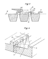
- the sieving device illustrated in the figures comprises on the one hand: - A sieve consisting of a metal surface 1 having perforations 2. These are slots or holes which have, in cross section, according to the known technique, from one side 13 to the other 14 of the surface 1 , a first narrow part 2a, with parallel walls 2d, of axis generally perpendicular to the surface of the sieve, and of inlet section 2c parallel to the surface of the sieve, followed by a second part which widens towards the outlet , forming a trapezoidal section 2b.
- this second part 2b is a truncated cone; on the other hand : - A hydrodynamic profile fin or foil which circulates at high speed in front of the face 13 of the screen, parallel to this face, in the direction indicated by the arrow in the figures.
- the movement of the fin 3 is communicated to the dough, which circulates along the surface of the sieve, and the good dough progressively crosses the perforations from the side 13 upstream, to the side 14 downstream.
- the upstream face 13 of the screen has obstacles 4 intended to break the component of the speed parallel to the speed of the liquid.
- the obstacles 4 are arranged in front of each perforation 12 in order to cause turbulence in the flow of the liquid for each perforation. These obstacles 4 often have varied profiles, but in general they have a general parallelpipedic or trapezoidal shape.
- This arrangement is to promote the formation of turbulence applied around the end of the obstacle and to guide the flow directly into the perforation 2.
- the height 5 of the obstacle is of the same order of magnitude as the width of the perforation (diameter in the case of holes), that is to say a few tenths of a millimeter.
- the height of the obstacle within the meaning of the invention is the distance between the plane 15 defined by the surface 1 of the screen and the face 12 parallel to said plane.
- the height of the obstacle is between 0.2 and 1 millimeter
- the width of the inlet section 2c of the perforation is between 0.1 and 1 millimeter, both of which may vary. independently. This characteristic combined with these orders of magnitude indeed seems to favor the formation of turbulence developing in the volume determined by the height of the obstacle and the perforation section, that is to say in a very small volume.
- Such sieves can be produced by machining the perforated sheet, the obstacle 4 being integrated into the mass of the sieve, the upper profile of the obstacle being obtained by milling, the perforation being obtained in a second step.
- They can also be produced by assembling bars 6 on crosspieces 7, with or without juxtaposition of said bars against each other, this embodiment making it possible to use various bar profiles.
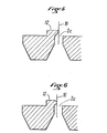
- the obstacle has a projecting downstream end 4a which projects into the section 2c itself.
- the section 2c in this case is slightly reduced by the projecting part 4a.
- the obstacle comprises an overhanging downstream part 4a which rises above the inlet section 2c of the perforation, and comes to partially cover it, thus forming a baffle of entry in front of the perforation, called zone 8 of access to the perforation.
- the lower part 9 of the obstacle is raised relative to the base surface of the screen, that is to say relative to the opposite edge 10 of the perforation so that the entry plane 11 into the area d 'access is inclined to the horizontal by an angle ⁇ between 0 and 90 °.
- the obstacle 4 completely covers the perforation 2: it overhangs at least slightly the opposite edge 10 of the perforation; in this variant, the baffle thus formed has an entry plane inclined relative to the horizontal at an angle ⁇ greater than 90 °.
- the shape of the end 4a can vary and have a more or less angular outline, or even rounded, as illustrated in FIGS. 5 and 6; therefore, it is not always possible to measure the precise inclination of the entry plane 11 in the access area.
- the plane 16 tangent to the end 4a of the obstacle 4 and perpendicular to the entry section 2c that is to say to the plane 15: - In the first and second variants, passes into the entry section 2c of perforation 2; - In the third variant, overhang in FIG. 3, passes beyond the inlet section 2c of the perforation.
Landscapes
- Engineering & Computer Science (AREA)
- Mechanical Engineering (AREA)
- Paper (AREA)
- Combined Means For Separation Of Solids (AREA)
- Filtration Of Liquid (AREA)
Applications Claiming Priority (2)
| Application Number | Priority Date | Filing Date | Title |
|---|---|---|---|
| FR8704833 | 1987-04-06 | ||
| FR8704833A FR2613389A1 (fr) | 1987-04-06 | 1987-04-06 | Perfectionnement aux tamis pour epurateurs de pate a papier |
Publications (2)
| Publication Number | Publication Date |
|---|---|
| EP0286535A1 true EP0286535A1 (de) | 1988-10-12 |
| EP0286535B1 EP0286535B1 (de) | 1991-05-29 |
Family
ID=9349852
Family Applications (1)
| Application Number | Title | Priority Date | Filing Date |
|---|---|---|---|
| EP88400827A Expired - Lifetime EP0286535B1 (de) | 1987-04-06 | 1988-04-06 | Siebe für Papierstoffreiniger |
Country Status (7)
| Country | Link |
|---|---|
| US (1) | US4898665A (de) |
| EP (1) | EP0286535B1 (de) |
| JP (1) | JPS63249793A (de) |
| DE (1) | DE3862986D1 (de) |
| ES (1) | ES2023500B3 (de) |
| FI (1) | FI92339C (de) |
| FR (1) | FR2613389A1 (de) |
Cited By (3)
| Publication number | Priority date | Publication date | Assignee | Title |
|---|---|---|---|---|
| FR2635125A1 (fr) * | 1988-08-08 | 1990-02-09 | Lamort E & M | Perfectionnement aux tamis pour epurateurs de pate a papier |
| WO1991008338A1 (de) * | 1989-12-06 | 1991-06-13 | Hermann Finckh Maschinenfabrik Gmbh & Co. | Sieb für drucksortierer für fasersuspensionen |
| EP1039021A1 (de) * | 1999-03-25 | 2000-09-27 | Voith Sulzer Papiertechnik Patent GmbH | Verfahren zum Nasssieben von Faserstoffsuspensionen in Drucksortierern und Drucksortierersieb |
Families Citing this family (5)
| Publication number | Priority date | Publication date | Assignee | Title |
|---|---|---|---|---|
| US5791495A (en) * | 1996-03-11 | 1998-08-11 | Beloit Technologies, Inc. | Paper pulp screen cylinder |
| FI118810B (fi) * | 2003-09-01 | 2008-03-31 | Anpap Oy | Sihtirakenne käytettäväksi kuitutuotteen valmistuksessa |
| JP4376151B2 (ja) * | 2004-08-09 | 2009-12-02 | 相川鉄工株式会社 | スクリーン装置 |
| US8381916B2 (en) * | 2005-05-26 | 2013-02-26 | Paul W. Bossen | Rotary aggregate washing and classification system |
| CN104338675A (zh) * | 2014-10-30 | 2015-02-11 | 安徽捷迅光电技术有限公司 | 椭圆形物料的分选装置 |
Citations (2)
| Publication number | Priority date | Publication date | Assignee | Title |
|---|---|---|---|---|
| US3939065A (en) * | 1972-08-31 | 1976-02-17 | Ahlfors S E E | Screening device |
| GB2067911A (en) * | 1980-01-28 | 1981-08-05 | Celleco Ab | Strainer for purification of pulp |
Family Cites Families (9)
| Publication number | Priority date | Publication date | Assignee | Title |
|---|---|---|---|---|
| FR629799A (fr) * | 1926-07-20 | 1927-11-17 | Perfectionnement aux installations de lavage de minéraux au moyen de courants liquidds dans les couloirs à poches d'évacuation | |
| US2038931A (en) * | 1934-04-21 | 1936-04-28 | Louis B Goldberg | Self cleaning screen for placer mining machines |
| US2827169A (en) * | 1954-12-07 | 1958-03-18 | Internat Pulp Products Inc | Screen plate |
| FR1539846A (fr) * | 1967-08-02 | 1968-09-20 | E Et M Lamort Fils Ets | Perfectionnement aux épurateurs notamment pour les pâtes à papier |
| JPS5637393A (en) * | 1979-08-30 | 1981-04-11 | Mitsubishi Heavy Ind Ltd | Screen apparatus for paper stock |
| DE3023746C2 (de) * | 1980-06-25 | 1986-04-10 | Ruhrkohle Ag, 4300 Essen | Fester Siebrost für Aufbereitungsanlagen, insbesondere für Verladungen von Steinkohle |
| CH649112A5 (de) * | 1980-10-03 | 1985-04-30 | Escher Wyss Gmbh | Verfahren zum fraktionieren von aus altpapier gewonnenem faserstoff sowie anlage zur ausfuehrung des verfahrens. |
| SE8107772L (sv) * | 1981-12-23 | 1983-06-06 | Karl Gunnar Malm | Silplat samt sett att framstella en dylik |
| FI67588C (fi) * | 1983-01-26 | 1985-04-10 | Ahlstroem Oy | Silplaot |
-
1987
- 1987-04-06 FR FR8704833A patent/FR2613389A1/fr not_active Withdrawn
-
1988
- 1988-04-04 US US07/177,502 patent/US4898665A/en not_active Expired - Fee Related
- 1988-04-05 FI FI881567A patent/FI92339C/fi not_active IP Right Cessation
- 1988-04-06 JP JP63083204A patent/JPS63249793A/ja active Pending
- 1988-04-06 ES ES88400827T patent/ES2023500B3/es not_active Expired - Lifetime
- 1988-04-06 EP EP88400827A patent/EP0286535B1/de not_active Expired - Lifetime
- 1988-04-06 DE DE8888400827T patent/DE3862986D1/de not_active Expired - Lifetime
Patent Citations (2)
| Publication number | Priority date | Publication date | Assignee | Title |
|---|---|---|---|---|
| US3939065A (en) * | 1972-08-31 | 1976-02-17 | Ahlfors S E E | Screening device |
| GB2067911A (en) * | 1980-01-28 | 1981-08-05 | Celleco Ab | Strainer for purification of pulp |
Cited By (5)
| Publication number | Priority date | Publication date | Assignee | Title |
|---|---|---|---|---|
| FR2635125A1 (fr) * | 1988-08-08 | 1990-02-09 | Lamort E & M | Perfectionnement aux tamis pour epurateurs de pate a papier |
| WO1991008338A1 (de) * | 1989-12-06 | 1991-06-13 | Hermann Finckh Maschinenfabrik Gmbh & Co. | Sieb für drucksortierer für fasersuspensionen |
| US5259512A (en) * | 1989-12-06 | 1993-11-09 | Hermann Finckh Maschinenfabrik Gmbh & Co. | Screen for pressure sorters for fiber suspensions |
| EP1039021A1 (de) * | 1999-03-25 | 2000-09-27 | Voith Sulzer Papiertechnik Patent GmbH | Verfahren zum Nasssieben von Faserstoffsuspensionen in Drucksortierern und Drucksortierersieb |
| US6273266B1 (en) | 1999-03-25 | 2001-08-14 | Voith Sulzer Papiertechnik Patent Gmbh | Process for the wet screening of stock suspensions in pressure graders and pressure graders screen |
Also Published As
| Publication number | Publication date |
|---|---|
| FI881567L (fi) | 1988-10-07 |
| FI881567A0 (fi) | 1988-04-05 |
| FI92339C (fi) | 1994-10-25 |
| JPS63249793A (ja) | 1988-10-17 |
| EP0286535B1 (de) | 1991-05-29 |
| FR2613389A1 (fr) | 1988-10-07 |
| US4898665A (en) | 1990-02-06 |
| DE3862986D1 (de) | 1991-07-04 |
| FI92339B (fi) | 1994-07-15 |
| ES2023500B3 (es) | 1992-01-16 |
Similar Documents
| Publication | Publication Date | Title |
|---|---|---|
| EP0286535B1 (de) | Siebe für Papierstoffreiniger | |
| EP0182688B1 (de) | Sieben für Reinigungsvorrichtungen und Verfahren zu ihrer Herstellung | |
| FR2629191A1 (fr) | Distributeur de liquide pour colonnes echangeuses de matieres et de chaleur | |
| FR2612081A1 (fr) | Perfectionnement aux tamis pour epurateur et a leur mode de fabrication | |
| CA1327471C (fr) | Dispositif d'alimentation en melange pateux | |
| EP0079811A1 (de) | Siebvorrichtungen für Papierstoffaufschwemmungen und ihre Siebe | |
| CA2195870C (en) | Method and apparatus for screening a fiber suspension | |
| EP1155185B1 (de) | Verfahren und vorrichtung zum filtrieren von faserbrei | |
| JP2003144804A (ja) | 油水分離装置 | |
| CA2469837C (fr) | Desencrage de pate a papier avec moyens de guidages comportant des passages de bulles | |
| EP0453348A1 (de) | Sieb zum Filtrieren und Klassifizieren von Faserbrei | |
| WO2002034991A1 (fr) | Installation de production d'une nappe non tissee dont le diffuseur est a distance du dispositif a fente d'etirage | |
| FR2767361A1 (fr) | Dispositif destine a influencer le decollement d'un courant d'un corps entoure par le courant | |
| FR2475919A1 (fr) | Plateau de distillation | |
| FR2613953A1 (fr) | Element plan de filtrage et de separation | |
| FR2635125A1 (fr) | Perfectionnement aux tamis pour epurateurs de pate a papier | |
| EP0150646B1 (de) | Anlage für die Koagulierung und Ausflockung von Flüssigkeiten, die kolloidale und/oder nichtkolloidale Stoffe enthalten | |
| CH659001A5 (fr) | Tamis rotatif. | |
| BE1009167A5 (fr) | Dispositif pour l'application d'un liquide de traitement sur une matiere defilant en une bande. | |
| FR2937565A1 (fr) | Separateur hydrodynamique pour nettoyer une veine de fluide | |
| FR2503748A1 (fr) | Procede et dispositif pour le traitement de vieux papiers | |
| FR2626906A1 (fr) | Partie humide d'une machine a papier a deux toiles filtrantes | |
| CH440947A (fr) | Caisse de distribution pour une suspension aqueuse de fibres | |
| FR2492648A1 (fr) | Filtre a cafe utilisable de facon permanenteÿa | |
| FR2524824A1 (fr) | Perfectionnements aux trommels trieurs |
Legal Events
| Date | Code | Title | Description |
|---|---|---|---|
| PUAI | Public reference made under article 153(3) epc to a published international application that has entered the european phase |
Free format text: ORIGINAL CODE: 0009012 |
|
| AK | Designated contracting states |
Kind code of ref document: A1 Designated state(s): DE ES FR GB IT SE |
|
| 17P | Request for examination filed |
Effective date: 19880916 |
|
| 17Q | First examination report despatched |
Effective date: 19900406 |
|
| GRAA | (expected) grant |
Free format text: ORIGINAL CODE: 0009210 |
|
| AK | Designated contracting states |
Kind code of ref document: B1 Designated state(s): DE ES FR GB IT SE |
|
| REF | Corresponds to: |
Ref document number: 3862986 Country of ref document: DE Date of ref document: 19910704 |
|
| ITF | It: translation for a ep patent filed | ||
| GBT | Gb: translation of ep patent filed (gb section 77(6)(a)/1977) | ||
| REG | Reference to a national code |
Ref country code: ES Ref legal event code: FG2A Ref document number: 2023500 Country of ref document: ES Kind code of ref document: B3 |
|
| PLBE | No opposition filed within time limit |
Free format text: ORIGINAL CODE: 0009261 |
|
| STAA | Information on the status of an ep patent application or granted ep patent |
Free format text: STATUS: NO OPPOSITION FILED WITHIN TIME LIMIT |
|
| 26N | No opposition filed | ||
| EAL | Se: european patent in force in sweden |
Ref document number: 88400827.7 |
|
| PGFP | Annual fee paid to national office [announced via postgrant information from national office to epo] |
Ref country code: FR Payment date: 19950315 Year of fee payment: 8 |
|
| PGFP | Annual fee paid to national office [announced via postgrant information from national office to epo] |
Ref country code: GB Payment date: 19950331 Year of fee payment: 8 |
|
| PGFP | Annual fee paid to national office [announced via postgrant information from national office to epo] |
Ref country code: ES Payment date: 19950419 Year of fee payment: 8 |
|
| PGFP | Annual fee paid to national office [announced via postgrant information from national office to epo] |
Ref country code: SE Payment date: 19950427 Year of fee payment: 8 |
|
| PGFP | Annual fee paid to national office [announced via postgrant information from national office to epo] |
Ref country code: DE Payment date: 19950620 Year of fee payment: 8 |
|
| PG25 | Lapsed in a contracting state [announced via postgrant information from national office to epo] |
Ref country code: GB Effective date: 19960406 |
|
| PG25 | Lapsed in a contracting state [announced via postgrant information from national office to epo] |
Ref country code: SE Effective date: 19960407 |
|
| PG25 | Lapsed in a contracting state [announced via postgrant information from national office to epo] |
Ref country code: ES Free format text: LAPSE BECAUSE OF NON-PAYMENT OF DUE FEES Effective date: 19960408 |
|
| GBPC | Gb: european patent ceased through non-payment of renewal fee |
Effective date: 19960406 |
|
| PG25 | Lapsed in a contracting state [announced via postgrant information from national office to epo] |
Ref country code: FR Effective date: 19961227 |
|
| PG25 | Lapsed in a contracting state [announced via postgrant information from national office to epo] |
Ref country code: DE Effective date: 19970101 |
|
| EUG | Se: european patent has lapsed |
Ref document number: 88400827.7 |
|
| REG | Reference to a national code |
Ref country code: FR Ref legal event code: ST |
|
| REG | Reference to a national code |
Ref country code: ES Ref legal event code: FD2A Effective date: 19990201 |
|
| PG25 | Lapsed in a contracting state [announced via postgrant information from national office to epo] |
Ref country code: IT Free format text: LAPSE BECAUSE OF NON-PAYMENT OF DUE FEES;WARNING: LAPSES OF ITALIAN PATENTS WITH EFFECTIVE DATE BEFORE 2007 MAY HAVE OCCURRED AT ANY TIME BEFORE 2007. THE CORRECT EFFECTIVE DATE MAY BE DIFFERENT FROM THE ONE RECORDED. Effective date: 20050406 |