EP0286550A1 - Verfahren zum automatischen Anbringen von Schutzelementen auf Gegenstände, insbesondere konditioniert in Rollen und Vorrichtung zur Durchführung dieses Verfahrens - Google Patents
Verfahren zum automatischen Anbringen von Schutzelementen auf Gegenstände, insbesondere konditioniert in Rollen und Vorrichtung zur Durchführung dieses Verfahrens Download PDFInfo
- Publication number
- EP0286550A1 EP0286550A1 EP88420097A EP88420097A EP0286550A1 EP 0286550 A1 EP0286550 A1 EP 0286550A1 EP 88420097 A EP88420097 A EP 88420097A EP 88420097 A EP88420097 A EP 88420097A EP 0286550 A1 EP0286550 A1 EP 0286550A1
- Authority
- EP
- European Patent Office
- Prior art keywords
- roller
- machine according
- protective
- drive
- combination
- Prior art date
- Legal status (The legal status is an assumption and is not a legal conclusion. Google has not performed a legal analysis and makes no representation as to the accuracy of the status listed.)
- Ceased
Links
Images


Classifications
-
- B—PERFORMING OPERATIONS; TRANSPORTING
- B65—CONVEYING; PACKING; STORING; HANDLING THIN OR FILAMENTARY MATERIAL
- B65B—MACHINES, APPARATUS OR DEVICES FOR, OR METHODS OF, PACKAGING ARTICLES OR MATERIALS; UNPACKING
- B65B25/00—Packaging other articles presenting special problems
- B65B25/14—Packaging paper or like sheets, envelopes, or newspapers, in flat, folded, or rolled form
- B65B25/146—Packaging paper or like sheets, envelopes, or newspapers, in flat, folded, or rolled form packaging rolled-up articles
- B65B25/148—Jumbo paper rolls
Definitions
- the invention relates to a process for automatically installing protective elements for products packaged in rolls in particular and to the machine for implementing the process.
- the object of the invention relates to the technical sector of handling flat-shaped materials.
- one of the wings of these cardboard angle elements has, at regular intervals, a plurality of profiled cutouts. in a triangle, to allow the bending of said angles.
- each angle In the case of products packaged in a roll, the angles are placed overlapping each of the circular edges, the ends of each angle, which can be positioned in superposition, are held together by means of, for example, an adhesive.
- an adhesive optionally, between each angle, can be arranged, according to the generatrices of the roll, a strip of corrugated cardboard, craft paper or other material.
- the invention set itself the aim of remedying these drawbacks, by automating the installation of these protective angles.
- the result is a characteristic process and a machine specially designed for its implementation, and shaped to achieve the desired goal.
- At least one roller is brought opposite a transfer device; - The diameter of the roller and its positioning are detected; - The transfer device is controlled to position the roller in combination with support means and for driving said roller in rotation; - At least one installation set is positioned in relation to at least one of the circular edges of the roller; - At least this circular edge is fitted peripherally with a means capable of ensuring, in combination with the rotation of the roller, the automatic positioning by winding, of the protective element; - We grab at least one protection element that is positioned in relation to drive and positioning and shaping means to bring it in cooperation with the winding means or means which equip the or each of roll edges; - Part of the protection element is detected; - We order a means capable of ensuring the voltage connection of the ends of the protection element (s) on at least one of the circular peripheral edges of the roller; - We retract the drive means and automatic positioning by rolling the protective element (s); - The roller equipped with the protective elements is transferred to the initial position;
- the processing machine comprises, in combination, the main means and arrangements below: - a conveyor for the supply of products packaged in rolls; - A device for transferring the roller to a positioning support member which is also arranged to allow the rotation of said roller to be driven at will; - At least one but preferably two sets of overlapping protective elements of the or each of the circular peripheral edges of the roll, each set being equipped with means capable of ensuring in combination with the rotation of the roll, the drive and the winding of said protective elements previously arranged and / or packaged in arrangements of the machine acting as a store; - Means for ensuring the tension coupling of the ends of the protective elements arranged on one or each of the circular edges of the roller.
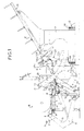
- the machine for the automatic laying of cardboard angles successively comprises the following main stations and arrangements, suitably mounted on a support frame: - a conveyor (A) for the supply of rolled products (R); - A transfer device (B) of the roller (R) on a support member (C) positioning further arranged to allow at will, the rotational drive of said roller; - At least one but preferably two sets of laying (D) of the angles (E) overlapping the or each of the circular peripheral edges of the roller (R), each assembly being equipped with means capable of ensuring, in combination with the rotation of the roller, the drive and the winding of said angles previously arranged and / or conditioned in arrangements of the machine serving as store (M); - Means for ensuring the tension coupling of the ends of angle irons arranged on the circular periphery of the roller.
- the conveyor (A) is arranged transversely in the front part of the frame and is constituted, in a known manner, by drive rollers (1) on which are mounted a support profile plane (2) shaped in section for allow centering and positioning of the roller (R).
- the transfer device (B) in the form of two articulated arms (3) whose free ends receive a support roller (4).
- each arm (3) is suitably profiled in order to present the support roller (4) parallel to the external lateral side of the conveyor, in relation to the generatrices of the roller (R).
- the articulation (3a) of each arm operates on a fixed part of the machine frame. Cylinders (5) or the like control the arms (3) in order to increase their controlled angular pivoting.
- the conveyor is equipped with sensor members (6) and (7) shaped to, respectively, detect the gauge of the roller, and position said roller very substantially along the main axis of the machine, d '' equidistant to the two installation sets (D).
- the sensor (7) controls a brake motor (B) secured to the conveyor.
- the transfer device is equipped with a support surface (9) suitably shaped to facilitate the transfer of the roller (R) onto the support member (C), in combination with the tilting effect of the arms (3) and pushing of the roller (4).
- the support member (C) is composed of a set of rollers (10, 11, 12) constituting, in combination, a support cradle.
- the roller (10), mounted transversely between two flanges (13) is motorized by being positively driven in rotation by means for example of a motor (14).
- the two other rollers (11) and (12) arranged in parallel while being angularly offset, are mounted free in rotation at the end of two profiled arms (15) and articulated by being subject to a actuator of the jack type (16) for example .
- each arm (15) takes place on the same part of the frame of the machine receiving the articulation (3a) of the arms (3).
- Each set of installation and each store are fixed on corresponding support flanges (17) and (17a) arranged facing each other and mounted with controlled transverse displacement capacity so as to be moved parallel in approach or in distance from one another.
- each of the flanges (17) and 17a) fitted with rolling members (18) cooperates with guide rails (19).
- the installation assemblies (D) are subject for example to geared motors (20) to ensure their relative displacement. These geared motors (20) are controlled by a feeler (21) associated with a proximity detector biased by the roller, in order to very precisely position the fitting assemblies (D) relative to the circular edges of said roller.
- Each installation set is equipped with a motori head sée (22) whose shaft (22a) is integral with an arm (23) which acts as a compass.
- This pair of arms (23), which can be positively driven in rotation by the motorized heads (22), is arranged in a plane parallel to that of the lateral sides of the roller.
- each compass (23), opposite their articulation is coupled to a member (24) shaped to ensure, in combination with the rotation of the roller (R), the automatic winding in tension of the angle iron (E) as it is driven, overlapping each of the circular edges of said roller (R).
- the winding means (24) consists of a double chain, the strands (24a) of which are braced by rollers (24b) mounted free to rotate.
- This chain (24) is wound in tension inside a drum (25) arranged very substantially in vertical alignment with each of the heads (22).
- Each installation assembly (D) also has a device (26) capable of driving and shaping the angles from the store.
- Each of the devices (26) is placed at the outlet of the corresponding magazine, in relation to each of the heads (22), and in alignment with in particular the winding chain (24). It is composed, for each of the heads, of a pneumatic or other suction cup (26a), in relation to the end of the lower angle disposed in the magazine, said suction cup being subject to an articulated arm (26b) shaped to fold said end and position it on a support roller (26c) mounted free to rotate.
- the support roller (26c) can be brought in a grooved pressure roller (26d) which drive positively in rotation and which aims both to drive the angle iron while making pre-folding marks.
- a grooved pressure roller (26d) which drive positively in rotation and which aims both to drive the angle iron while making pre-folding marks.
- two systems of toothed belts (26e) and (26f) which delimit try in combination a guide and drive tunnel to bring the angle between the winding chain (24) and the roller (R).
- the toothed belts (26e) and (26f) are mounted with different sets of motor pinions (26g).
- the guide tunnel resulting from the part in juxtaposition of the two toothed belts is profiled, in a semi-circular manner, to act as a conformator by preforming the angle to facilitate its winding.
- the coupling means consist of an adhesive tape applicator (27) conditioned on a reel (28) being subject to drive means (29) controlled by a sensor which detects the rear part of the angle iron.
- a member of any known and suitable type ensures the cut to the desired length of the adhesive tape.
- Each store (M) is preferably made up of two compartments (30) and (31) each corresponding to different lengths of angles depending on the size of the roller (R). As indicated above, these compartments are mounted with transverse displacement capacity so that one or the other of said compartments is positioned in correspondence in particular with the drive device (26), taking into account the indication provided by the sensor ( 6) detection of the roll gauge.
- Each of the compartments is mounted on the corresponding support flange (17a) in an inclined manner to facilitate, by gravitation, the departure of the angles.
- the angles (E) are packaged in the superimposed compartments in combination with support and retaining side panels arranged angularly to take account of the angular offset of the angles resulting from their stacking.
- the various organs and control means are obviously suitably connected to a central unit which aims to ensure the synchronism of the various movements having regard to the desired operating characteristics.
- the various members are controlled by a programmable automaton.
- the roller (R) is brought by the conveyor (1 - 2).
- the sensors (6) and (7) detect the size of the roller in order, on the one hand, to ensure their positioning in the axis of symmetry of the laying assemblies and, on the other hand, to select the corresponding compartment (30) or (31) from the store.
- the transfer device (B) is controlled.
- the arms (3) under the effect of the jack (5), pivot angularly, so that the roller (R) bears on the roller (4) and pushes it in the direction of the support cradle (10, 11, 12) passing through the support and transfer plane (9).
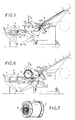
- the articulated support arms (15) of the rollers (11) and (12) are angularly positioned, so that said rollers (11) and (12) are located at the plane (9 ) to ensure the retention of the roller (R) during the transfer. There therefore appears to be a combined movement of synchronism between the two pairs of arms (3) and (15) (FIG. 3).
- the roller (R) is positioned in combination with the rollers (10) and (11) or (10) and (12) depending on the diameter of the roller (R).
- the probe (21) is urged to control, by means of the geared motors (20), the displacement of the laying assemblies (D) for the positioning of their head (22) opposite and in combination with the circular transverse edges of the roller (R).
- the motorized heads (22) are then controlled, which has the effect of circularly driving the compasses (23) and simultaneously winding the chain (24) secured to said compass, around the roller (R) in tangency with the circular edges of said roller.
- the winding of the chain (24) takes place automatically taking into account the combined effect of the rotation of the roller (R) and the tensile force exerted by the compass.
- the device (26) After positioning the winding chain (24), the device (26) is stressed.
- the end of the lower angle iron arranged in the magazine is palpated by the pneumatic suction cup (26a), the arm (26b) being angularly controlled to fold the gripped end of the angle iron and bring it into contact with the roller. crazy support (figure?).
- the grooved drive roller (26d) is tilted to come into pressure on the end of the gripped angle iron to cause it to be driven and marked.
- the angle is then engaged between the two sets of toothed drive belts (26e) and (26f) which act as a shaper, to direct and guide the angle between the chain (24) and the roller (R).
- the angle iron is automatically wound overlapping the corresponding circular edge of said roller, being perfectly guided and maintained by the chain.
- the applicator member (27) of adhesive tape is urged to deposit a piece of said tape on the overlapping end parts of the angle.
- the adhesive tape can be applied only on the angles, or in combination with part of the roller (R).
- the drive compasses (23) of each of the chains (24) are brought back to the initial position for conditioning said chain (24) inside its support roller (25).
- the roller (R) is therefore free.
- the pairs of arms (15) and (3) are then controlled in opposite directions and in synchronism, to effect the transfer of the roller (R) from the support and centering cradle to the conveyor.
- the type of means for coupling the protective elements may be other than adhesive tape, for example glue, staples.
Landscapes
- Engineering & Computer Science (AREA)
- Mechanical Engineering (AREA)
- Hydrogenated Pyridines (AREA)
- Replacement Of Web Rolls (AREA)
Applications Claiming Priority (2)
| Application Number | Priority Date | Filing Date | Title |
|---|---|---|---|
| FR8704526A FR2612883B1 (fr) | 1987-03-24 | 1987-03-24 | Procede de pose automatique d'elements de protection pour les produits conditionnes en rouleau notamment et la machine pour la mise en oeuvre du procede |
| FR8704526 | 1987-03-24 |
Publications (1)
| Publication Number | Publication Date |
|---|---|
| EP0286550A1 true EP0286550A1 (de) | 1988-10-12 |
Family
ID=9349649
Family Applications (1)
| Application Number | Title | Priority Date | Filing Date |
|---|---|---|---|
| EP88420097A Ceased EP0286550A1 (de) | 1987-03-24 | 1988-03-23 | Verfahren zum automatischen Anbringen von Schutzelementen auf Gegenstände, insbesondere konditioniert in Rollen und Vorrichtung zur Durchführung dieses Verfahrens |
Country Status (2)
| Country | Link |
|---|---|
| EP (1) | EP0286550A1 (de) |
| FR (1) | FR2612883B1 (de) |
Cited By (3)
| Publication number | Priority date | Publication date | Assignee | Title |
|---|---|---|---|---|
| EP0517149A1 (de) * | 1991-06-03 | 1992-12-09 | Lamiflex Verpackungstechnik Gmbh | Verfahren zum Verpacken von Metallcoils |
| WO1998010987A1 (en) * | 1996-09-13 | 1998-03-19 | Bf Engineering S.R.L. | Coil packaging plant |
| CN112407397A (zh) * | 2020-11-20 | 2021-02-26 | 广州市香港科大霍英东研究院 | 端盖自动拣选喂送装置 |
Citations (2)
| Publication number | Priority date | Publication date | Assignee | Title |
|---|---|---|---|---|
| DE1586018A1 (de) * | 1967-06-21 | 1970-07-23 | Druko Maschb Gmbh | Maschine zum Einpacken von zylindrischen Koerpern |
| US4201028A (en) * | 1977-09-15 | 1980-05-06 | Chippewa Paper Products Corporation | Apparatus for applying end caps to rolls of sheet stock |
-
1987
- 1987-03-24 FR FR8704526A patent/FR2612883B1/fr not_active Expired
-
1988
- 1988-03-23 EP EP88420097A patent/EP0286550A1/de not_active Ceased
Patent Citations (2)
| Publication number | Priority date | Publication date | Assignee | Title |
|---|---|---|---|---|
| DE1586018A1 (de) * | 1967-06-21 | 1970-07-23 | Druko Maschb Gmbh | Maschine zum Einpacken von zylindrischen Koerpern |
| US4201028A (en) * | 1977-09-15 | 1980-05-06 | Chippewa Paper Products Corporation | Apparatus for applying end caps to rolls of sheet stock |
Cited By (3)
| Publication number | Priority date | Publication date | Assignee | Title |
|---|---|---|---|---|
| EP0517149A1 (de) * | 1991-06-03 | 1992-12-09 | Lamiflex Verpackungstechnik Gmbh | Verfahren zum Verpacken von Metallcoils |
| WO1998010987A1 (en) * | 1996-09-13 | 1998-03-19 | Bf Engineering S.R.L. | Coil packaging plant |
| CN112407397A (zh) * | 2020-11-20 | 2021-02-26 | 广州市香港科大霍英东研究院 | 端盖自动拣选喂送装置 |
Also Published As
| Publication number | Publication date |
|---|---|
| FR2612883A1 (fr) | 1988-09-30 |
| FR2612883B1 (fr) | 1989-07-28 |
Similar Documents
| Publication | Publication Date | Title |
|---|---|---|
| FR2623176A1 (fr) | Appareillage et procede pour traiter la partie d'extremite d'une feuille de papier en rouleau disposee en un emplacement de raccordement | |
| EP0245187B1 (de) | Einrichtung zum automatischen Aufladen von Rollen auf Abwicklungsmaschinen | |
| FR2956482A1 (fr) | Procede et dispositif d'equilibrage du balourd d'une roue de vehicule | |
| FR2642741A1 (fr) | Cartouche et appareil distributeur de profile | |
| FR2467807A1 (fr) | Dispositif de distribution d'une feuille d'emballage pour rouleaux de papier ou objets analogues | |
| US4795522A (en) | Bead filler applicator | |
| CA2240062A1 (en) | Method and apparatus for forming an envelope over an article | |
| EP2112106B1 (de) | Verfahren und Vorrichtung zum Stoßschneiden und -verkleben für Rundschälmaschine | |
| EP0301989A1 (de) | Maschine zum Abwickeln von Bahnen mit Gestellen für Wickelrollen | |
| FR2477513A1 (fr) | Dispositif deviateur pour bandes de papier en particulier | |
| EP0893241A1 (de) | Verfahren und vorrichtung zum automatischen verkleben einer wärmeschrumpfenden kunststoff-folie auf den boden einer offenen kiste. | |
| EP0718227B1 (de) | Vorrichtung zum Einsetzen und Spleissen von Papierbahnrollen oder dergleichen | |
| EP0795504B1 (de) | Maschine zum kontinuierlichen Abwickeln von Rollen mit zumindest einer Einrichtung zum gleichzeitigen Abwickeln von zwei paarweise oder koaxial angeordneten Rollen | |
| FR2724227A1 (fr) | Procede et dispositif pour preparer des masselottes d'equilibrage adhesives pour des jantes de vehicules automobiles. | |
| FR2584053A1 (fr) | Procede et dispositif de stockage temporaire d'articles imprimes se presentant selon une formation disposee a la maniere de tuiles etagees. | |
| FR2725154A1 (fr) | Procede et dispositif d'application d'une bande de roulement premoulee et prevulcanisee sur une carcasse de pneumatique | |
| WO1991013424A1 (fr) | Machine a decouper en bandes, contrecoller et bobiner les affiches pour panneaux publicitaires a prismes tournants | |
| FR2643487A1 (fr) | Appareil de depose et pose d'affiches predecoupees en bandes sur des panneaux publicitaires | |
| EP0252844B1 (de) | Automatische Vorrichtung zum Bearbeiten, insbesondere zum Schneiden von Bändern | |
| FR2557491A1 (fr) | Machine pour la coupe et la pose de troncons de ruban souple | |
| EP0376806A1 (de) | Verfahren zum Ummanteln von zusammengebauten Schachtelteilen und Einrichtung zur Durchführung dieses Verfahrens | |
| EP0699610A1 (de) | Vorrichtung zum Schneiden und klebstofflosen Anbringen des Bahnanfangs für eine neue Wickelrolle auf den Wickelkern eines Wicklers | |
| CH637595A5 (fr) | Machine pour former des rouleaux a partir d'une bande de papier. | |
| FR2651761A1 (fr) | Appareil pour la pose automatique notamment d'un ruban adhesif sur un produit. | |
| FR2497781A1 (fr) | Procede pour changer les bobines et les mandrins des machines d'enroulement sans axe |
Legal Events
| Date | Code | Title | Description |
|---|---|---|---|
| PUAI | Public reference made under article 153(3) epc to a published international application that has entered the european phase |
Free format text: ORIGINAL CODE: 0009012 |
|
| AK | Designated contracting states |
Kind code of ref document: A1 Designated state(s): AT BE CH DE ES GB GR IT LI LU NL SE |
|
| 17P | Request for examination filed |
Effective date: 19881212 |
|
| 17Q | First examination report despatched |
Effective date: 19900927 |
|
| STAA | Information on the status of an ep patent application or granted ep patent |
Free format text: STATUS: THE APPLICATION HAS BEEN REFUSED |
|
| 18R | Application refused |
Effective date: 19910323 |