EP0286584B1 - Procédé pour le fonctionnement du dispositif d'emmagasinage de fil de trame dans un métier à tisser - Google Patents
Procédé pour le fonctionnement du dispositif d'emmagasinage de fil de trame dans un métier à tisser Download PDFInfo
- Publication number
- EP0286584B1 EP0286584B1 EP88810149A EP88810149A EP0286584B1 EP 0286584 B1 EP0286584 B1 EP 0286584B1 EP 88810149 A EP88810149 A EP 88810149A EP 88810149 A EP88810149 A EP 88810149A EP 0286584 B1 EP0286584 B1 EP 0286584B1
- Authority
- EP
- European Patent Office
- Prior art keywords
- accumulator
- control
- control device
- drum
- weft thread
- Prior art date
- Legal status (The legal status is an assumption and is not a legal conclusion. Google has not performed a legal analysis and makes no representation as to the accuracy of the status listed.)
- Expired - Lifetime
Links
- 238000000034 method Methods 0.000 title claims description 8
- 239000002245 particle Substances 0.000 claims description 3
- 238000009941 weaving Methods 0.000 description 15
- 238000011156 evaluation Methods 0.000 description 13
- 238000001514 detection method Methods 0.000 description 5
- 108010076504 Protein Sorting Signals Proteins 0.000 description 4
- 238000004804 winding Methods 0.000 description 3
- 230000007257 malfunction Effects 0.000 description 2
- 229910000760 Hardened steel Inorganic materials 0.000 description 1
- VVQNEPGJFQJSBK-UHFFFAOYSA-N Methyl methacrylate Chemical compound COC(=O)C(C)=C VVQNEPGJFQJSBK-UHFFFAOYSA-N 0.000 description 1
- 229920005372 Plexiglas® Polymers 0.000 description 1
- 230000004888 barrier function Effects 0.000 description 1
- 230000005540 biological transmission Effects 0.000 description 1
- 230000015572 biosynthetic process Effects 0.000 description 1
- 230000000903 blocking effect Effects 0.000 description 1
- 238000007664 blowing Methods 0.000 description 1
- 239000000919 ceramic Substances 0.000 description 1
- 238000001816 cooling Methods 0.000 description 1
- 238000013016 damping Methods 0.000 description 1
- 239000000835 fiber Substances 0.000 description 1
- 238000003780 insertion Methods 0.000 description 1
- 230000037431 insertion Effects 0.000 description 1
- 238000012544 monitoring process Methods 0.000 description 1
- 210000000056 organ Anatomy 0.000 description 1
- 238000012545 processing Methods 0.000 description 1
- 230000005855 radiation Effects 0.000 description 1
- 230000002123 temporal effect Effects 0.000 description 1
- 230000007704 transition Effects 0.000 description 1
- 239000012780 transparent material Substances 0.000 description 1
- 230000003313 weakening effect Effects 0.000 description 1
Images

Classifications
-
- D—TEXTILES; PAPER
- D03—WEAVING
- D03D—WOVEN FABRICS; METHODS OF WEAVING; LOOMS
- D03D47/00—Looms in which bulk supply of weft does not pass through shed, e.g. shuttleless looms, gripper shuttle looms, dummy shuttle looms
- D03D47/34—Handling the weft between bulk storage and weft-inserting means
- D03D47/36—Measuring and cutting the weft
- D03D47/361—Drum-type weft feeding devices
- D03D47/367—Monitoring yarn quantity on the drum
-
- D—TEXTILES; PAPER
- D03—WEAVING
- D03D—WOVEN FABRICS; METHODS OF WEAVING; LOOMS
- D03D47/00—Looms in which bulk supply of weft does not pass through shed, e.g. shuttleless looms, gripper shuttle looms, dummy shuttle looms
- D03D47/34—Handling the weft between bulk storage and weft-inserting means
- D03D47/36—Measuring and cutting the weft
- D03D47/361—Drum-type weft feeding devices
- D03D47/362—Drum-type weft feeding devices with yarn retaining devices, e.g. stopping pins
-
- D—TEXTILES; PAPER
- D03—WEAVING
- D03D—WOVEN FABRICS; METHODS OF WEAVING; LOOMS
- D03D47/00—Looms in which bulk supply of weft does not pass through shed, e.g. shuttleless looms, gripper shuttle looms, dummy shuttle looms
- D03D47/34—Handling the weft between bulk storage and weft-inserting means
- D03D47/36—Measuring and cutting the weft
- D03D47/361—Drum-type weft feeding devices
- D03D47/362—Drum-type weft feeding devices with yarn retaining devices, e.g. stopping pins
- D03D47/363—Construction or control of the yarn retaining devices
-
- D—TEXTILES; PAPER
- D03—WEAVING
- D03D—WOVEN FABRICS; METHODS OF WEAVING; LOOMS
- D03D47/00—Looms in which bulk supply of weft does not pass through shed, e.g. shuttleless looms, gripper shuttle looms, dummy shuttle looms
- D03D47/34—Handling the weft between bulk storage and weft-inserting means
- D03D47/36—Measuring and cutting the weft
- D03D47/361—Drum-type weft feeding devices
- D03D47/364—Yarn braking means acting on the drum
-
- B—PERFORMING OPERATIONS; TRANSPORTING
- B65—CONVEYING; PACKING; STORING; HANDLING THIN OR FILAMENTARY MATERIAL
- B65H—HANDLING THIN OR FILAMENTARY MATERIAL, e.g. SHEETS, WEBS, CABLES
- B65H2557/00—Means for control not provided for in groups B65H2551/00 - B65H2555/00
- B65H2557/30—Control systems architecture or components, e.g. electronic or pneumatic modules; Details thereof
- B65H2557/33—Control systems architecture or components, e.g. electronic or pneumatic modules; Details thereof for digital control, e.g. for generating, counting or comparing pulses
Definitions
- the invention relates to a method for operating a weft thread store of a weaving machine, with a stationary drum and a control device for the weft thread wound around the drum, the control device having at least two sensors.
- Such a weft store is described in Swiss Patent No. 647,999. It explains a detection device for the thread to be wound onto the drum and at least one further one for the weft thread to be pulled off the drum. After the second detection device has reported a certain number of signals as a result of the passing weft thread to the control of the weft thread store, a blocking device is switched on, which prevents further thread turns from being pulled off the drum of the weft thread store. The accuracy of the length dimension of the weft thread to be inserted into the weaving machine depends on the function of the second detection device.
- the signals of the sensors of the control device are compared by an evaluation unit and are only taken into account for the control of the weft thread store and the weaving machine if the chronological sequence of the signals corresponds to at least one expectation model.
- the absence of a single expected signal from a sensor of the control device is only taken into account if the absence of a corresponding signal from at least one second sensor is also determined by the evaluation unit.
- a surplus signal that is not expected from a sensor for example as a result of a dirt particle in the sensitive area of the sensor, is not taken into account for the control if it occurs only occasionally and is not detected by at least a second sensor. In this way, interference in the area of the control device, be it in the area of the sensors or to keep away from the control of the weft store and the weaving machine within the control device.
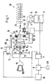
- the weft thread 10 to be processed in the weaving machine 30 is drawn off from a yarn bobbin 100 by the weft thread store 1, in that a winder 12 winds the weft thread in a plurality of turns on a stationary drum 11, whereupon the weft thread 10 through the control device 19 and the blowing nozzle 33 into the through the warp threads 31 and 32 of the weaving machine 30 formed shed is entered.
- the weft thread enters the weft thread store 1 through the funnel 172 of the winder shaft 17 and then passes through the winder 12 fastened in the winder shaft is formed from the eyelets 121 and 122 and the intermediate tube 120.
- a rod 173 is located diametrically opposite the winder as a mass balance.
- the winder shaft 17 is mounted in the bearings 171 in the housing 15 and is driven by a controlled electric motor 13 via the belt drive 140, 141 and 142.
- the drum 11 of the weft thread store is mounted on the winder shaft by means of the radial bearing 18. It is prevented from rotating by magnet pairs 16, one of which is located in the housing 15 and another in the drum 11.
- the drum shell 113 of the drum extends only partially over the circumference of the drum.
- the drum is formed by brackets 110, the bent ends of which converge radially at flange 111.
- the flange 111 serves to hold the stirrups 110 in place and enables radial adjustment of the stirrups so that the drum circumference can be changed in accordance with the weft thread length required in the weaving machine 30.
- the weft thread After the weft thread has been deposited on the conical section 115 of the drum 11, the weft thread turns slide further to the right in FIG. 2 onto the cylindrical section of the drum 11, in order then to be withdrawn discontinuously.
- the start and end of the removal process are controlled by the locking pin 21, which can be moved radially against the stop 22 in the drum 11 by the electromagnet 20.
- the magnet 20 has a connection piece 23 for compressed air, which is used for cooling and damping the magnet armature.
- the cap 112 engages, which forms a narrow annular gap with the drum for braking the thread turns running out of the accumulator.
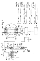
- the control device 19 is fastened to the cap 112 by means of the bolts 114 and is essentially formed from the control ring 190, the transmitter 191 and the receiver 192.
- the control ring 190 is made of transparent material, for example plexiglass.
- the balloon of the running weft is limited on its conical inside.
- the trailing edge of the control ring 190 is protected by the wear ring 193, which is made of hardened steel or ceramic, for example.
- the transmitter 191 and 191 ' forms a light barrier with the receiver 192.
- Transmitter 191 and receiver 192 are each surrounded by a jacket 194. Since the beam path 195 or 195 'according to FIG. 4 is broken at the transition of the beams into the interior of the control ring 190 or out of the control ring, transmitter 191 and receiver 192 must be arranged in accordance with the angles of refraction of the beams.
- the beam paths 195 and 195 'according to FIG. 4 are briefly interrupted by the weft thread 10 running from the drum 11, whereupon signals are given to the amplifiers A and B.
- the temporal sequence of the signals is compared in the evaluation unit W according to FIG. 4 with an expected model.
- the expected model of the signal sequence in the case of a double arrangement of transmitters 191 and receivers 192 is shown in FIG. 5a.
- the evaluation unit W forwards a signal to the controller SS for the magnet 20 when a certain number of regular pulses has been registered in the evaluation unit W.
- the locking pin 21 is pressed against the stop 22 by means of the magnet 20, whereby the Pull-off process of the thread 10 comes to a standstill from the drum 11.
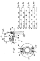
- the control signals in an embodiment of the control device according to FIG. 4 are alternately generated by the receivers 192 and 192 ', the control device 19 is able to detect interference signals and from an effective disruption of the yarn path, for example as a result of tearing off To distinguish weft.
- the non-hatched rectangle is intended to represent an interference signal for the amplifier A, which is generated, for example, by a dirt particle crossing the beam path 195 '. Since the other expected signals from the receivers 192 or 192 'arrive according to the program, the evaluation unit W does not detect a fault in the weft thread 10 in this case and consequently suppresses the interference signal.
- FIG. 5c Another possible interference in the signal processing is shown in FIG. 5c.
- the dashed, non-hatched rectangle is intended to show that an expected signal does not arrive in amplifier B. This disturbance can exist if a thin spot in the weft yarn crosses the beam path 195 and only leads to an insignificant weakening of the radiation, which is not recognized as an interruption of the beam path.
- FIG. 8c which is indicated by several expected non-arriving signals and leads to the immediate shutdown of the weaving machine and the weft thread store via the control S.
- Fig. 1 the control of the electric motor 13 for the winder 12 of the weft thread is shown.
- the electric motor 13 has the task of driving the winder 12 via the belt drive 14 in such a way that the number of thread windings drawn off the drum 13 is immediately replaced by new ones Winding weft threads are replaced by the bobbin 100 so that there are always enough thread windings on the drum 11.
- the evaluation unit W continuously reports the number of effectively drawn thread turns to the comparator V, which on the other hand registers the number of new thread turns for the electric motor via the sensor 125 or in response from the control SE for the electric motor.
- the difference value between newly placed thread turns and drawn thread turns is transmitted from the comparator to the controller R, which compares the difference value from the comparator V with the target value from the input device SW and, depending on the result, issues control commands to the control SE of the electric motor.
Landscapes
- Engineering & Computer Science (AREA)
- Textile Engineering (AREA)
- Looms (AREA)
Claims (4)
Applications Claiming Priority (2)
| Application Number | Priority Date | Filing Date | Title |
|---|---|---|---|
| CH1349/87 | 1987-04-08 | ||
| CH134987 | 1987-04-08 |
Publications (2)
| Publication Number | Publication Date |
|---|---|
| EP0286584A1 EP0286584A1 (fr) | 1988-10-12 |
| EP0286584B1 true EP0286584B1 (fr) | 1991-05-08 |
Family
ID=4208398
Family Applications (1)
| Application Number | Title | Priority Date | Filing Date |
|---|---|---|---|
| EP88810149A Expired - Lifetime EP0286584B1 (fr) | 1987-04-08 | 1988-03-09 | Procédé pour le fonctionnement du dispositif d'emmagasinage de fil de trame dans un métier à tisser |
Country Status (4)
| Country | Link |
|---|---|
| US (1) | US4848417A (fr) |
| EP (1) | EP0286584B1 (fr) |
| JP (1) | JPS63270839A (fr) |
| DE (1) | DE3862670D1 (fr) |
Families Citing this family (11)
| Publication number | Priority date | Publication date | Assignee | Title |
|---|---|---|---|---|
| US5221960A (en) * | 1988-12-07 | 1993-06-22 | Iro Ab | Opto-electronic detector apparatus |
| JP2880289B2 (ja) * | 1989-11-03 | 1999-04-05 | イーロー アーベー | 糸貯留供給装置で生じる回転振動を防止する方法と糸貯留供給装置 |
| NL9101312A (nl) * | 1991-07-31 | 1993-02-16 | Rueti | Inrichting voor het vormen van een voorraadwikkel uit een vanaf een garenvoorraad aangevoerde draad. |
| NL9201344A (nl) * | 1992-07-24 | 1994-02-16 | Rueti | Inrichting voor het voeden van een periodiek werkende garen-verwerkende inrichting. |
| BE1009172A3 (nl) * | 1995-02-28 | 1996-12-03 | Picanol Nv | Grijperweefmachine met inslagdetectiemiddelen. |
| DE19526216A1 (de) * | 1995-07-18 | 1997-01-23 | Iro Ab | Verfahren zum Abtasten eines Fadens und Fadenabzugssensor |
| DE19915349A1 (de) * | 1999-04-06 | 2000-10-19 | Dornier Gmbh Lindauer | Verfahren zum Vermeiden einer Bremsverzögerung bei einem Webstop in einer Webmaschine |
| IT1307712B1 (it) * | 1999-04-27 | 2001-11-14 | Lgl Electronics Spa | Metodo di sorveglianza dell'inserzione di trama nei sistemi dialimentazione di telai a getto di fluido con premisuratore del filato |
| NL1014729C2 (nl) * | 2000-03-23 | 2001-09-25 | Te Strake Bv | Werkwijze voor het opnemen en tellen van van een trommel aflopende wikkelingen, alsmede een inrichting voor het uitvoeren van deze werkwijze. |
| ITTO20020029U1 (it) * | 2002-02-08 | 2003-08-08 | L G L Electronics Spa | ,,dispositivo alimentatore di trama per macchine tessili con sistema di fissaggio del tamburo fisso al corpo motore perfezionato,, |
| JP5821646B2 (ja) * | 2012-01-17 | 2015-11-24 | 株式会社豊田自動織機 | 複数の緯糸を同時に緯入れする流体噴射式織機の緯糸切れ検出装置 |
Family Cites Families (9)
| Publication number | Priority date | Publication date | Assignee | Title |
|---|---|---|---|---|
| CH647999A5 (de) * | 1980-06-17 | 1985-02-28 | Rueti Ag Maschf | Fadenliefervorrichtung fuer textilmaschinen und verfahren zum betrieb der fadenliefervorrichtung. |
| JPS59500975A (ja) * | 1982-05-12 | 1984-05-31 | アクテイエボラゲツト イロ | 織機制御システム |
| US4546263A (en) * | 1982-12-06 | 1985-10-08 | Nissan Motor Company, Limited | Weft sensor for a loom |
| JPS59106543A (ja) * | 1982-12-13 | 1984-06-20 | 日産自動車株式会社 | 断片織機の緯糸供給装置 |
| JPS59187647A (ja) * | 1983-04-01 | 1984-10-24 | 津田駒工業株式会社 | 織機の緯欠点検出停止装置 |
| JPS60162838A (ja) * | 1984-01-27 | 1985-08-24 | 株式会社豊田自動織機製作所 | 流体噴射式織機における緯入れ方法 |
| US4614311A (en) * | 1985-01-30 | 1986-09-30 | Kasuga Denki Co., Ltd. | Yarn storage and delivery apparatus |
| JPH0733614B2 (ja) * | 1985-04-05 | 1995-04-12 | 津田駒工業株式会社 | よこ入れ制御方法およびその装置 |
| JPH0749612B2 (ja) * | 1986-01-22 | 1995-05-31 | 津田駒工業株式会社 | ドラム式緯糸測長貯留装置の緯糸解舒検知装置 |
-
1988
- 1988-03-09 EP EP88810149A patent/EP0286584B1/fr not_active Expired - Lifetime
- 1988-03-09 DE DE8888810149T patent/DE3862670D1/de not_active Expired - Lifetime
- 1988-04-04 US US07/176,941 patent/US4848417A/en not_active Expired - Fee Related
- 1988-04-07 JP JP63084246A patent/JPS63270839A/ja active Pending
Also Published As
| Publication number | Publication date |
|---|---|
| EP0286584A1 (fr) | 1988-10-12 |
| JPS63270839A (ja) | 1988-11-08 |
| US4848417A (en) | 1989-07-18 |
| DE3862670D1 (de) | 1991-06-13 |
Similar Documents
| Publication | Publication Date | Title |
|---|---|---|
| EP0286590B1 (fr) | Dispositif d'emmagasinage de fil de trame pour un métier à tisser | |
| EP3802927B1 (fr) | Ligne de filature à anneau et son procédé de fonctionnement | |
| DE2111671C3 (de) | Fadenspeichereinrichtung für Textilmaschinen | |
| DE68902750T2 (de) | Garnlieferungsvorrichtung fuer textilmaschinen. | |
| EP0286584A1 (fr) | Procédé pour le fonctionnement du dispositif d'emmagasinage de fil de trame dans un métier à tisser | |
| CH647999A5 (de) | Fadenliefervorrichtung fuer textilmaschinen und verfahren zum betrieb der fadenliefervorrichtung. | |
| DE2262425A1 (de) | Vorrichtung zur automatischen ueberwachung und steuerung einer eine anzahl von spulenkoerpern mit einem garnfaden bespulenden maschine | |
| DE3917055C2 (de) | Verfahren und Einrichtung zum Überwachen des Produktionsvorgangs der Spuleinrichtungen einer Kreuzspulen herstellenden Maschine | |
| DE3213631C2 (de) | Steuereinrichtung für eine Spulstelle eines Spulautomaten | |
| CH667886A5 (de) | Verfahren und vorrichtung zur steuerung einer luntenstop-anordnung einer spinnmaschine. | |
| DE60003895T2 (de) | Verfahren und vorrichtung zur garnüberwachung | |
| DE2533754A1 (de) | Verfahren und vorrichtung zum verarbeiten von straengen | |
| EP0016871B1 (fr) | Procédé et dispositif pour obtenir des longueurs de fil prédéterminées et précises sur bobine | |
| CH659460A5 (de) | Vorrichtung zur ermittlung defektbehafteter wickel fuer garnhaspel. | |
| DE2124288C3 (de) | Einrichtung zum Steuern einer automatischen Kreuzspulmaschine | |
| EP0679599A2 (fr) | Dispositif de contrôle pour ruban de fibres | |
| DE3806165C2 (de) | Verfahren zur Kontrolle des Umspulvorganges bei einem Spulautomaten | |
| DE3245574C2 (de) | Verfahren zum Überwachen des Texturiervorgangs bei einem Friktionsfalschdrall-Aggregat | |
| EP0251268B1 (fr) | Dispositif pour la filature de fils | |
| DE60204103T2 (de) | Vorrichtung zur Detektion von Spiel zwischen Streckwerkrollen einer Spinnmaschine | |
| DE4039121A1 (de) | Vorrichtung und verfahren zum ueberwachen eines laufenden fadens bei einer textilmaschine, insbesondere kabliermaschine | |
| DE19642222A1 (de) | Vorrichtung zum Herstellen von Coregarn | |
| EP0580548A1 (fr) | Procédé et dispositif pour le bobinage d'un fil | |
| EP1473391B1 (fr) | Système et procédé d'insertion de trame | |
| DE3411927C2 (fr) |
Legal Events
| Date | Code | Title | Description |
|---|---|---|---|
| PUAI | Public reference made under article 153(3) epc to a published international application that has entered the european phase |
Free format text: ORIGINAL CODE: 0009012 |
|
| 17P | Request for examination filed |
Effective date: 19880311 |
|
| AK | Designated contracting states |
Kind code of ref document: A1 Designated state(s): BE CH DE FR GB IT LI |
|
| 17Q | First examination report despatched |
Effective date: 19900301 |
|
| ITF | It: translation for a ep patent filed | ||
| GRAA | (expected) grant |
Free format text: ORIGINAL CODE: 0009210 |
|
| AK | Designated contracting states |
Kind code of ref document: B1 Designated state(s): BE CH DE FR GB IT LI |
|
| PG25 | Lapsed in a contracting state [announced via postgrant information from national office to epo] |
Ref country code: GB Effective date: 19910508 |
|
| REF | Corresponds to: |
Ref document number: 3862670 Country of ref document: DE Date of ref document: 19910613 |
|
| EN | Fr: translation not filed | ||
| PG25 | Lapsed in a contracting state [announced via postgrant information from national office to epo] |
Ref country code: FR Effective date: 19910927 |
|
| GBV | Gb: ep patent (uk) treated as always having been void in accordance with gb section 77(7)/1977 [no translation filed] | ||
| PLBE | No opposition filed within time limit |
Free format text: ORIGINAL CODE: 0009261 |
|
| STAA | Information on the status of an ep patent application or granted ep patent |
Free format text: STATUS: NO OPPOSITION FILED WITHIN TIME LIMIT |
|
| PG25 | Lapsed in a contracting state [announced via postgrant information from national office to epo] |
Ref country code: LI Effective date: 19920331 Ref country code: CH Effective date: 19920331 |
|
| 26N | No opposition filed | ||
| REG | Reference to a national code |
Ref country code: CH Ref legal event code: PL |
|
| REG | Reference to a national code |
Ref country code: FR Ref legal event code: ST |
|
| PGFP | Annual fee paid to national office [announced via postgrant information from national office to epo] |
Ref country code: DE Payment date: 19930213 Year of fee payment: 6 |
|
| PGFP | Annual fee paid to national office [announced via postgrant information from national office to epo] |
Ref country code: BE Payment date: 19930216 Year of fee payment: 6 |
|
| PG25 | Lapsed in a contracting state [announced via postgrant information from national office to epo] |
Ref country code: BE Effective date: 19940331 |
|
| BERE | Be: lapsed |
Owner name: GEBRUDER SULZER A.G. Effective date: 19940331 |
|
| PG25 | Lapsed in a contracting state [announced via postgrant information from national office to epo] |
Ref country code: DE Effective date: 19941201 |
|
| PG25 | Lapsed in a contracting state [announced via postgrant information from national office to epo] |
Ref country code: IT Free format text: LAPSE BECAUSE OF NON-PAYMENT OF DUE FEES Effective date: 20050309 |