EP0286590A1 - Dispositif d'emmagasinage de fil de trame pour un métier à tisser - Google Patents
Dispositif d'emmagasinage de fil de trame pour un métier à tisser Download PDFInfo
- Publication number
- EP0286590A1 EP0286590A1 EP88810186A EP88810186A EP0286590A1 EP 0286590 A1 EP0286590 A1 EP 0286590A1 EP 88810186 A EP88810186 A EP 88810186A EP 88810186 A EP88810186 A EP 88810186A EP 0286590 A1 EP0286590 A1 EP 0286590A1
- Authority
- EP
- European Patent Office
- Prior art keywords
- ring
- transmitter
- receiver
- thread
- control device
- Prior art date
- Legal status (The legal status is an assumption and is not a legal conclusion. Google has not performed a legal analysis and makes no representation as to the accuracy of the status listed.)
- Granted
Links
- 238000009941 weaving Methods 0.000 claims abstract description 10
- 239000000463 material Substances 0.000 claims description 5
- VVQNEPGJFQJSBK-UHFFFAOYSA-N Methyl methacrylate Chemical compound COC(=O)C(C)=C VVQNEPGJFQJSBK-UHFFFAOYSA-N 0.000 claims description 3
- 229920005372 Plexiglas® Polymers 0.000 claims description 3
- 239000012780 transparent material Substances 0.000 claims description 3
- 238000012544 monitoring process Methods 0.000 claims description 2
- 230000005855 radiation Effects 0.000 claims description 2
- 238000011109 contamination Methods 0.000 abstract description 2
- 238000011156 evaluation Methods 0.000 description 4
- 238000004804 winding Methods 0.000 description 4
- 238000007664 blowing Methods 0.000 description 2
- 229910000760 Hardened steel Inorganic materials 0.000 description 1
- 230000004888 barrier function Effects 0.000 description 1
- 239000000919 ceramic Substances 0.000 description 1
- 238000001816 cooling Methods 0.000 description 1
- 238000013016 damping Methods 0.000 description 1
- 238000006073 displacement reaction Methods 0.000 description 1
- 238000003780 insertion Methods 0.000 description 1
- 230000037431 insertion Effects 0.000 description 1
- 238000000034 method Methods 0.000 description 1
- 238000012806 monitoring device Methods 0.000 description 1
- 230000003287 optical effect Effects 0.000 description 1
- 239000002245 particle Substances 0.000 description 1
- 230000004044 response Effects 0.000 description 1
- 239000007779 soft material Substances 0.000 description 1
Images


Classifications
-
- D—TEXTILES; PAPER
- D03—WEAVING
- D03D—WOVEN FABRICS; METHODS OF WEAVING; LOOMS
- D03D47/00—Looms in which bulk supply of weft does not pass through shed, e.g. shuttleless looms, gripper shuttle looms, dummy shuttle looms
- D03D47/34—Handling the weft between bulk storage and weft-inserting means
- D03D47/36—Measuring and cutting the weft
- D03D47/361—Drum-type weft feeding devices
- D03D47/367—Monitoring yarn quantity on the drum
-
- D—TEXTILES; PAPER
- D03—WEAVING
- D03D—WOVEN FABRICS; METHODS OF WEAVING; LOOMS
- D03D47/00—Looms in which bulk supply of weft does not pass through shed, e.g. shuttleless looms, gripper shuttle looms, dummy shuttle looms
- D03D47/34—Handling the weft between bulk storage and weft-inserting means
- D03D47/36—Measuring and cutting the weft
- D03D47/361—Drum-type weft feeding devices
- D03D47/362—Drum-type weft feeding devices with yarn retaining devices, e.g. stopping pins
-
- D—TEXTILES; PAPER
- D03—WEAVING
- D03D—WOVEN FABRICS; METHODS OF WEAVING; LOOMS
- D03D47/00—Looms in which bulk supply of weft does not pass through shed, e.g. shuttleless looms, gripper shuttle looms, dummy shuttle looms
- D03D47/34—Handling the weft between bulk storage and weft-inserting means
- D03D47/36—Measuring and cutting the weft
- D03D47/361—Drum-type weft feeding devices
- D03D47/362—Drum-type weft feeding devices with yarn retaining devices, e.g. stopping pins
- D03D47/363—Construction or control of the yarn retaining devices
-
- B—PERFORMING OPERATIONS; TRANSPORTING
- B65—CONVEYING; PACKING; STORING; HANDLING THIN OR FILAMENTARY MATERIAL
- B65H—HANDLING THIN OR FILAMENTARY MATERIAL, e.g. SHEETS, WEBS, CABLES
- B65H2513/00—Dynamic entities; Timing aspects
- B65H2513/10—Speed
- B65H2513/11—Speed angular
Definitions
- the invention relates to a weft thread store for a weaving machine, with a stationary drum and a control device for the weft thread wound around the drum, the control device being arranged on the take-off side of the store.
- Such a weft store is known from EP application No. 011 308. It describes two types of winding counters for the weft thread running off the drum.
- a light transmitter for example, can be arranged in the vicinity of the storage drum, the rays of which are reflected on the drum circumference and reflected to a receiver arranged near the transmitter. If the weft thread crosses the light rays during the pull-off from the drum, a signal is sent to the control of the weft thread store, which can correspond, for example, to a drawn-off turn.
- the arrangement of an optical sensor for the weft thread in a cylindrical eyelet between the drum of the weft thread store and the insertion device, in this case a blowing nozzle is described.
- Both arrangements of the monitoring devices for the weft thread have the disadvantage that the weft thread can assume any position in the space between the sensor and in the first case the storage drum or in the second case the rotationally symmetrical body.
- the distance between the weft thread and the exit surface of the light rays from the control device can vary according to the clear width of the space at this point.
- deposits can settle on the exit surface without being regularly stripped by the passing weft thread.
- Such deposits for example in the form of thread particles, can disrupt the beam path from the transmitter to the receiver and trigger false signals, which can lead to interruption of the weaving operation. Such interruptions are undesirable because they affect the efficiency of the weaving machine.
- control device is arranged behind the trailing edge of the storage drum and in front of a thread eyelet in the area in which a thread balloon forms between the storage device and the thread eyelet during the thread take-off from the storage drum, and in that the control device is provided by a inside by the Weft-coatable ring is formed, through the inner boundary surface of which light rays can emerge or enter from a transmitter to a receiver in the ring, the cone angle of the ring being open against the storage drum.
- the transmitter and receiver within the ring are seated in pockets which are sealed off from the inner boundary surface of the ring.
- the ring of the control device must be made of transparent material, for example plexiglass, so that the light rays from the transmitter or receiver in a pocket can pass through the material of the ring unhindered to the inner boundary surface of the ring.
- At least one pair of sensors consisting of a light transmitter and light receiver is advantageously arranged in the ring of the control device in such a way that the light beams from the transmitter to the receiver form a chord within a circle lying in the inner boundary surface.
- the radiation axes of the transmitter and receiver together with the chord form the angle of refraction of the light as it passes through the inner boundary surface.
- the transmitter and receiver can be arranged side by side so that the light rays from the transmitter are reflected from the projection to the receiver inside the ring after passing through the inner boundary surface of the ring.
- several sensors each consisting of a transmitter and a receiver, can also be present in the ring.
- the sensors are located in bores within the ring, which are open against the inside of the ring. Since the weft thread is pulled from the The storage drum brushes against the inside of the ring, which limits the thread balloon and causes it to deflect through the ring. If the ring is made of soft material, the edge of the ring causing the thread deflection is protected against wear by an annular insert made of hard material.
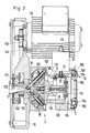
- the weft thread 10 to be processed in the weaving machine 30 is drawn off from a yarn bobbin 100 by the weft thread store 1, in that a winder 12 winds the weft thread in several turns on a stationary drum 11, whereupon the weft thread 10 through the control device 19 and the blowing nozzle 33 into the through the Warp threads 31 and 32 of the weaving machine 30 formed shed is entered.
- the weft thread enters the weft thread store 1 through the funnel 172 of the winder shaft 17 and then passes through the winder 12 which is fastened in the winder shaft and which is formed from the eyelets 121 and 122 and the tube 120 located therebetween.
- a rod 173 is located diametrically opposite the winder as a mass balance.
- the winder shaft 17 is mounted in the bearings 171 in the housing 15 and is driven by a controlled electric motor 13 via the belt drive 140, 141 and 142.
- the drum 11 of the weft thread store is mounted on the winder shaft by means of the radial bearing 18. It is prevented from rotating by magnet pairs 16, one of which is located in the housing 15 and another in the drum 11.
- the drum shell 113 of the drum extends only partially over the circumference of the drum.
- the drum is formed by brackets 110, the bent ends of which converge radially at flange 111.
- the flange 111 serves to hold the stirrups 110 in place and enables radial adjustment of the stirrups so that the drum circumference can be changed in accordance with the weft thread length required in the weaving machine 30.
- the weft thread After the weft thread has been deposited on the conical section 115 of the drum 11, the weft thread turns slide further to the right in FIG. 2 onto the cylindrical section of the drum 11, in order then to be withdrawn discontinuously.
- the start and end of the removal process are controlled by the locking pin 21, which can be moved radially against the stop 22 in the drum 11 by the electromagnet 20.
- the magnet 20 has a connecting piece 23 for compressed air, which is used for cooling and damping the magnet armature.
- the control device 19 is fastened to the cap 112 by means of the bolts 114 and is essentially formed from the control ring 190, the transmitter 191 and the receiver 192.
- the control ring 190 is preferably made of transparent material, for example plexiglass.
- the balloon of the running weft thread is limited on its inside.
- the trailing edge of the control ring 190 is protected by the wear ring 193, which is made of hardened steel or ceramic, for example.
- the control ring is axially adjustable by means of a displacement of the bolts 114, as a result of which the weft thread running off can be more or less braked.
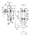
- the transmitter 191 or 191 ⁇ forms a light barrier with the receiver 192.
- Transmitter 191 and receiver 192 are each surrounded by a jacket 194. Since the beam path 195 or 195 ⁇ according to FIG. 4 is broken when the beams pass into the interior of the control ring 190 or out of the control ring, the transmitter 191 and the receiver 192 must be arranged in accordance with the angles of refraction of the beams.
- the beam paths 195 and 195 ⁇ according to FIG. 4 are briefly interrupted by the weft thread 10 running from the drum 11, whereupon signals are sent to the amplifiers A and B to the evaluation unit W.
- the evaluation unit W forwards a signal to the controller SS for the magnet 20 when a certain number of regular pulses have been registered in the evaluation unit W. is.
- the locking pin 21 is pressed against the stop 22 by means of the magnet 20, as a result of which the thread 10 is pulled off the drum 11 to a standstill.
- FIG. 5 and 6 another embodiment of a weft thread store according to the invention is shown.
- the light beam from the transmitter 191 or 191 ⁇ is reflected by a reflector cone 24 according to Fig. 5.6 to a receiver 192 or 192 ⁇ located directly next to the transmitter.
- a receiver 192 or 192 ⁇ located directly next to the transmitter.
- only one signal is received alternately in the counters A and B when the weft thread is withdrawn from the drum 11 of the weft thread store 1.
- Fig. 1 the control of the electric motor 13 for the winder 12 of the weft thread is shown.
- the electric motor 13 has the task of driving the winder 12 via the belt drive 14 in such a way that the number of thread windings drawn off the drum 13 is immediately replaced by new winding of weft thread from the bobbin 100, so that there are always sufficient thread windings on the drum 11 .
- the evaluation unit W continuously reports the number of effectively drawn thread turns to the comparator V, which on the other hand registers the number of new thread turns for the electric motor via the sensor 125 or in response from the control SE for the electric motor.
- the difference value between newly placed thread turns and drawn thread turns is transmitted from the comparator to the controller R, which compares the difference value from the comparator V with the target value from the input device SW and, depending on the result, issues control commands to the control SE of the electric motor.
Landscapes
- Engineering & Computer Science (AREA)
- Textile Engineering (AREA)
- Looms (AREA)
Applications Claiming Priority (2)
| Application Number | Priority Date | Filing Date | Title |
|---|---|---|---|
| CH134787 | 1987-04-08 | ||
| CH1347/87 | 1987-04-08 |
Publications (2)
| Publication Number | Publication Date |
|---|---|
| EP0286590A1 true EP0286590A1 (fr) | 1988-10-12 |
| EP0286590B1 EP0286590B1 (fr) | 1991-05-08 |
Family
ID=4208354
Family Applications (1)
| Application Number | Title | Priority Date | Filing Date |
|---|---|---|---|
| EP88810186A Expired - Lifetime EP0286590B1 (fr) | 1987-04-08 | 1988-03-22 | Dispositif d'emmagasinage de fil de trame pour un métier à tisser |
Country Status (4)
| Country | Link |
|---|---|
| US (1) | US4852617A (fr) |
| EP (1) | EP0286590B1 (fr) |
| JP (1) | JPS63270838A (fr) |
| DE (1) | DE3862671D1 (fr) |
Cited By (4)
| Publication number | Priority date | Publication date | Assignee | Title |
|---|---|---|---|---|
| EP0401699A3 (fr) * | 1989-06-06 | 1991-01-16 | L.G.L. ELECTRONICS S.p.A. | Dispositif pour compter les enroulements se déroulant d'un fournisseur de fil de trame dans un métier à tisser |
| WO1992003604A1 (fr) * | 1990-08-21 | 1992-03-05 | Iro Ab | Dispositif d'amenee et de mesure du fil de trame et son procede de commande |
| NL1014729C2 (nl) * | 2000-03-23 | 2001-09-25 | Te Strake Bv | Werkwijze voor het opnemen en tellen van van een trommel aflopende wikkelingen, alsmede een inrichting voor het uitvoeren van deze werkwijze. |
| WO2005028351A1 (fr) * | 2003-08-29 | 2005-03-31 | Iro Ab | Appareil d'alimentation mesureur |
Families Citing this family (15)
| Publication number | Priority date | Publication date | Assignee | Title |
|---|---|---|---|---|
| DE3911411A1 (de) * | 1989-04-07 | 1990-10-11 | Iro Ab | Elektronisch gesteuertes schussfaden-verarbeitungs-aggregat |
| JP2796384B2 (ja) * | 1989-12-22 | 1998-09-10 | 津田駒工業株式会社 | ドラム式緯糸測長貯留装置の解舒センサ |
| EP0505317A1 (fr) * | 1991-03-19 | 1992-09-23 | Gebrüder Sulzer Aktiengesellschaft | Dispositif de guidage dans un métier à tisser avec des bobines de trames fixes |
| JPH04135988U (ja) * | 1991-05-30 | 1992-12-17 | 株式会社豊田中央研究所 | エアジエツト織機における緯糸供給速度測定装置 |
| SE469448B (sv) * | 1991-09-27 | 1993-07-05 | Rydborn S A O | Optisk oevervakningsanordning foer att detektera om en traad aer i roerelse |
| DE19609095A1 (de) * | 1996-03-08 | 1997-09-11 | Iro Ab | Fadenliefergerät |
| IT1292277B1 (it) * | 1997-04-24 | 1999-01-29 | Lgl Electronics Spa | Tastatore ottico perfezionato per la sorveglianza della riserva di filato negli apparecchi alimentatori di trama ed apparecchio |
| ITTO20010013A1 (it) * | 2001-01-12 | 2002-07-12 | Lgl Electronics Spa | Metodo e dispositivo per il controllo della riserva di trama negli alimentatori di trama a telai di tessitura ad inserzione meccanica includ |
| ITTO20010569A1 (it) * | 2001-06-14 | 2002-12-14 | Lgl Electronics Spa | Dispositivo di regolarizzazione dello svolgimento delle spire di filodella riserva di trama, dal tamburo degli alimentatori di trama per te |
| ITMI20111983A1 (it) | 2011-11-02 | 2013-05-03 | Btsr Int Spa | Dispositivo alimentatore positivo per alimentare a tensione costante fili metallici |
| ITMI20112046A1 (it) * | 2011-11-11 | 2013-05-12 | Btsr Int Spa | Dispositivo alimentatore di filo ad accumulo perfezionato |
| ITMI20112091A1 (it) | 2011-11-17 | 2013-05-18 | Btsr Int Spa | Alimentatore di filo, del tipo ad accumulo e con freno magnetico |
| ITMI20112267A1 (it) | 2011-12-15 | 2013-06-16 | Btsr Int Spa | Dispositivo di alimentazione di filo ad una macchina tessile |
| ITMI20112369A1 (it) | 2011-12-23 | 2013-06-24 | Btsr Int Spa | Metodo e dispositivo ad accumulo di filato per alimentare un filo senza creare torsioni dello stesso |
| ITMI20112414A1 (it) | 2011-12-28 | 2013-06-29 | Btsr Int Spa | Sistema e metodo perfezionati per alimentare a tensione costante fili metallici |
Citations (3)
| Publication number | Priority date | Publication date | Assignee | Title |
|---|---|---|---|---|
| GB2005739A (en) * | 1977-09-29 | 1979-04-25 | Savio & C Spa | Device of controlling the tension of yarn unwinding from ayarn supporting body |
| WO1982004446A1 (fr) * | 1981-06-17 | 1982-12-23 | Peeters Johan T | Dispositif de preparation de la trame pour metiers a tisser pneumatiques |
| EP0111308A2 (fr) * | 1982-12-13 | 1984-06-20 | Nissan Motor Co., Ltd. | Détecteur pour contrôler l'alimentation du fil de trame |
Family Cites Families (5)
| Publication number | Priority date | Publication date | Assignee | Title |
|---|---|---|---|---|
| CH472518A (de) * | 1966-12-13 | 1969-05-15 | Sulzer Ag | Webmaschine mit Schussfaden-Zwischenspeicher |
| CH523196A (de) * | 1970-05-14 | 1972-05-31 | Sulzer Ag | Speichereinrichtung für fadenartiges Material |
| JPS5669410A (en) * | 1979-11-09 | 1981-06-10 | Ntn Toyo Bearing Co Ltd | Automatic lash adjuster for sealed-up valve and method of assembling said adjuster |
| JPS6034688U (ja) * | 1983-08-12 | 1985-03-09 | 内藤 逸司 | てんぷら油過熱による火災予知警報器 |
| BE903115A (nl) * | 1985-08-26 | 1986-02-26 | Picanol Nv | Optische inslagwachter voor weefmachines met een u-vormig riet |
-
1988
- 1988-03-22 EP EP88810186A patent/EP0286590B1/fr not_active Expired - Lifetime
- 1988-03-22 DE DE8888810186T patent/DE3862671D1/de not_active Expired - Lifetime
- 1988-04-04 US US07/176,944 patent/US4852617A/en not_active Expired - Fee Related
- 1988-04-07 JP JP63084245A patent/JPS63270838A/ja active Pending
Patent Citations (3)
| Publication number | Priority date | Publication date | Assignee | Title |
|---|---|---|---|---|
| GB2005739A (en) * | 1977-09-29 | 1979-04-25 | Savio & C Spa | Device of controlling the tension of yarn unwinding from ayarn supporting body |
| WO1982004446A1 (fr) * | 1981-06-17 | 1982-12-23 | Peeters Johan T | Dispositif de preparation de la trame pour metiers a tisser pneumatiques |
| EP0111308A2 (fr) * | 1982-12-13 | 1984-06-20 | Nissan Motor Co., Ltd. | Détecteur pour contrôler l'alimentation du fil de trame |
Cited By (5)
| Publication number | Priority date | Publication date | Assignee | Title |
|---|---|---|---|---|
| EP0401699A3 (fr) * | 1989-06-06 | 1991-01-16 | L.G.L. ELECTRONICS S.p.A. | Dispositif pour compter les enroulements se déroulant d'un fournisseur de fil de trame dans un métier à tisser |
| WO1992003604A1 (fr) * | 1990-08-21 | 1992-03-05 | Iro Ab | Dispositif d'amenee et de mesure du fil de trame et son procede de commande |
| NL1014729C2 (nl) * | 2000-03-23 | 2001-09-25 | Te Strake Bv | Werkwijze voor het opnemen en tellen van van een trommel aflopende wikkelingen, alsmede een inrichting voor het uitvoeren van deze werkwijze. |
| WO2001071077A1 (fr) * | 2000-03-23 | 2001-09-27 | Te Strake B.V. | Procede de detection et comptage des spires extraites d'une bobine, et dispositif associe |
| WO2005028351A1 (fr) * | 2003-08-29 | 2005-03-31 | Iro Ab | Appareil d'alimentation mesureur |
Also Published As
| Publication number | Publication date |
|---|---|
| DE3862671D1 (de) | 1991-06-13 |
| US4852617A (en) | 1989-08-01 |
| EP0286590B1 (fr) | 1991-05-08 |
| JPS63270838A (ja) | 1988-11-08 |
Similar Documents
| Publication | Publication Date | Title |
|---|---|---|
| EP0286590B1 (fr) | Dispositif d'emmagasinage de fil de trame pour un métier à tisser | |
| DE2111671C3 (de) | Fadenspeichereinrichtung für Textilmaschinen | |
| CH647999A5 (de) | Fadenliefervorrichtung fuer textilmaschinen und verfahren zum betrieb der fadenliefervorrichtung. | |
| DE2225918A1 (de) | Verfahren fuer den gebremsten abzug fadenfoermigen materials von einem wickelkoerper einer speichereinrichtung fuer textilmaschinen und einrichtung zur durchfuehrung des verfahrens | |
| EP0786026B1 (fr) | Systeme de controle des fils de trame dans un metier a tisser circulaire | |
| DE7735237U1 (de) | Fadenliefervorrichtung fuer textilmaschinen | |
| DE1510310B1 (de) | Drehteller zum Ablegen von Faserbaendern in Spinnkannen | |
| EP0286584B1 (fr) | Procédé pour le fonctionnement du dispositif d'emmagasinage de fil de trame dans un métier à tisser | |
| EP0837829B1 (fr) | Detecteur optoelectronique et dispositif de mesure et d'amenee de fil de trame | |
| DE2533754A1 (de) | Verfahren und vorrichtung zum verarbeiten von straengen | |
| DE3049426C2 (de) | Verfahren und Vorrichtung zum Spleissen von zwei Garn- oder Fadenenden in einem Spleisskopf | |
| EP0305971B1 (fr) | Procédé et dispositif de filature par fausse torsion | |
| EP1327015B1 (fr) | Appareil d'alimentation | |
| EP0110150A1 (fr) | Dispositif de filature à tuyère | |
| DE2203608A1 (de) | Verfahren und Einrichtung zum Reinigen der Spinnturbinen von Offen-End-Spinneinrichtungen | |
| EP0440944A1 (fr) | Procédé et dispositif de texturation de fils | |
| WO1990011396A1 (fr) | Dispositif pour passer un fil dans le magasin de fils de trame d'un metier automatique | |
| DE2716017C2 (de) | Fadenbremse an einem Fadenspeicher | |
| EP0464378B1 (fr) | Dispositif fournisseur de fil | |
| DE3874505T2 (de) | Vorrichtung zum aufsuchen eines gerissenen fadenendes auf einer im aufbau befindlichen fadenwicklung. | |
| EP0505317A1 (fr) | Dispositif de guidage dans un métier à tisser avec des bobines de trames fixes | |
| EP0477208B1 (fr) | Procede et dispositif de texturation a l'air | |
| DE60013683T2 (de) | Verfahren und Vorrichtung zur Steuerung von Rotationssignale des Fadenzuführungsrohr in Fadenliefervorrichtungen für Webmaschinen | |
| DE19926675A1 (de) | Verfahren zum Offenend-Spinnen und Offenend-Spinnvorrichtung | |
| DE2460031A1 (de) | Vorrichtung zur falschdrallerzeugung bei thermoplastischen garnen |
Legal Events
| Date | Code | Title | Description |
|---|---|---|---|
| PUAI | Public reference made under article 153(3) epc to a published international application that has entered the european phase |
Free format text: ORIGINAL CODE: 0009012 |
|
| 17P | Request for examination filed |
Effective date: 19880324 |
|
| AK | Designated contracting states |
Kind code of ref document: A1 Designated state(s): BE CH DE FR GB IT LI |
|
| 17Q | First examination report despatched |
Effective date: 19900806 |
|
| ITF | It: translation for a ep patent filed | ||
| GRAA | (expected) grant |
Free format text: ORIGINAL CODE: 0009210 |
|
| AK | Designated contracting states |
Kind code of ref document: B1 Designated state(s): BE CH DE FR GB IT LI |
|
| PG25 | Lapsed in a contracting state [announced via postgrant information from national office to epo] |
Ref country code: GB Effective date: 19910508 |
|
| REF | Corresponds to: |
Ref document number: 3862671 Country of ref document: DE Date of ref document: 19910613 |
|
| EN | Fr: translation not filed | ||
| PG25 | Lapsed in a contracting state [announced via postgrant information from national office to epo] |
Ref country code: FR Effective date: 19910927 |
|
| GBV | Gb: ep patent (uk) treated as always having been void in accordance with gb section 77(7)/1977 [no translation filed] | ||
| PLBE | No opposition filed within time limit |
Free format text: ORIGINAL CODE: 0009261 |
|
| STAA | Information on the status of an ep patent application or granted ep patent |
Free format text: STATUS: NO OPPOSITION FILED WITHIN TIME LIMIT |
|
| PG25 | Lapsed in a contracting state [announced via postgrant information from national office to epo] |
Ref country code: LI Effective date: 19920331 Ref country code: CH Effective date: 19920331 |
|
| 26N | No opposition filed | ||
| REG | Reference to a national code |
Ref country code: CH Ref legal event code: PL |
|
| REG | Reference to a national code |
Ref country code: FR Ref legal event code: ST |
|
| PGFP | Annual fee paid to national office [announced via postgrant information from national office to epo] |
Ref country code: DE Payment date: 19990224 Year of fee payment: 12 |
|
| PGFP | Annual fee paid to national office [announced via postgrant information from national office to epo] |
Ref country code: BE Payment date: 19990319 Year of fee payment: 12 |
|
| PG25 | Lapsed in a contracting state [announced via postgrant information from national office to epo] |
Ref country code: BE Free format text: LAPSE BECAUSE OF NON-PAYMENT OF DUE FEES Effective date: 20000331 |
|
| BERE | Be: lapsed |
Owner name: GEBRUDER SULZER A.G. Effective date: 20000331 |
|
| PG25 | Lapsed in a contracting state [announced via postgrant information from national office to epo] |
Ref country code: DE Free format text: LAPSE BECAUSE OF NON-PAYMENT OF DUE FEES Effective date: 20010103 |
|
| PG25 | Lapsed in a contracting state [announced via postgrant information from national office to epo] |
Ref country code: IT Free format text: LAPSE BECAUSE OF NON-PAYMENT OF DUE FEES;WARNING: LAPSES OF ITALIAN PATENTS WITH EFFECTIVE DATE BEFORE 2007 MAY HAVE OCCURRED AT ANY TIME BEFORE 2007. THE CORRECT EFFECTIVE DATE MAY BE DIFFERENT FROM THE ONE RECORDED. Effective date: 20050322 |