EP0286603A2 - Vorrichtung zur Abgabe einer zu gefrierenden Flüssigkeit in einer Anlage zur Herstellung von Eiswürfeln - Google Patents
Vorrichtung zur Abgabe einer zu gefrierenden Flüssigkeit in einer Anlage zur Herstellung von Eiswürfeln Download PDFInfo
- Publication number
- EP0286603A2 EP0286603A2 EP88830125A EP88830125A EP0286603A2 EP 0286603 A2 EP0286603 A2 EP 0286603A2 EP 88830125 A EP88830125 A EP 88830125A EP 88830125 A EP88830125 A EP 88830125A EP 0286603 A2 EP0286603 A2 EP 0286603A2
- Authority
- EP
- European Patent Office
- Prior art keywords
- rod
- fluid
- rotation
- self
- chambers
- Prior art date
- Legal status (The legal status is an assumption and is not a legal conclusion. Google has not performed a legal analysis and makes no representation as to the accuracy of the status listed.)
- Withdrawn
Links
Images
Classifications
-
- B—PERFORMING OPERATIONS; TRANSPORTING
- B05—SPRAYING OR ATOMISING IN GENERAL; APPLYING FLUENT MATERIALS TO SURFACES, IN GENERAL
- B05B—SPRAYING APPARATUS; ATOMISING APPARATUS; NOZZLES
- B05B1/00—Nozzles, spray heads or other outlets, with or without auxiliary devices such as valves, heating means
- B05B1/34—Nozzles, spray heads or other outlets, with or without auxiliary devices such as valves, heating means designed to influence the nature of flow of the liquid or other fluent material, e.g. to produce swirl
- B05B1/3405—Nozzles, spray heads or other outlets, with or without auxiliary devices such as valves, heating means designed to influence the nature of flow of the liquid or other fluent material, e.g. to produce swirl to produce swirl
- B05B1/341—Nozzles, spray heads or other outlets, with or without auxiliary devices such as valves, heating means designed to influence the nature of flow of the liquid or other fluent material, e.g. to produce swirl to produce swirl before discharging the liquid or other fluent material, e.g. in a swirl chamber upstream the spray outlet
- B05B1/3421—Nozzles, spray heads or other outlets, with or without auxiliary devices such as valves, heating means designed to influence the nature of flow of the liquid or other fluent material, e.g. to produce swirl to produce swirl before discharging the liquid or other fluent material, e.g. in a swirl chamber upstream the spray outlet with channels emerging substantially tangentially in the swirl chamber
- B05B1/3426—Nozzles, spray heads or other outlets, with or without auxiliary devices such as valves, heating means designed to influence the nature of flow of the liquid or other fluent material, e.g. to produce swirl to produce swirl before discharging the liquid or other fluent material, e.g. in a swirl chamber upstream the spray outlet with channels emerging substantially tangentially in the swirl chamber the channels emerging in the swirl chamber perpendicularly to the outlet axis
-
- B—PERFORMING OPERATIONS; TRANSPORTING
- B05—SPRAYING OR ATOMISING IN GENERAL; APPLYING FLUENT MATERIALS TO SURFACES, IN GENERAL
- B05B—SPRAYING APPARATUS; ATOMISING APPARATUS; NOZZLES
- B05B3/00—Spraying or sprinkling apparatus with moving outlet elements or moving deflecting elements
- B05B3/02—Spraying or sprinkling apparatus with moving outlet elements or moving deflecting elements with rotating elements
- B05B3/04—Spraying or sprinkling apparatus with moving outlet elements or moving deflecting elements with rotating elements driven by the liquid or other fluent material discharged, e.g. the liquid actuating a motor before passing to the outlet
- B05B3/06—Spraying or sprinkling apparatus with moving outlet elements or moving deflecting elements with rotating elements driven by the liquid or other fluent material discharged, e.g. the liquid actuating a motor before passing to the outlet by jet reaction
-
- F—MECHANICAL ENGINEERING; LIGHTING; HEATING; WEAPONS; BLASTING
- F25—REFRIGERATION OR COOLING; COMBINED HEATING AND REFRIGERATION SYSTEMS; HEAT PUMP SYSTEMS; MANUFACTURE OR STORAGE OF ICE; LIQUEFACTION SOLIDIFICATION OF GASES
- F25C—PRODUCING, WORKING OR HANDLING ICE
- F25C1/00—Producing ice
- F25C1/04—Producing ice by using stationary moulds
- F25C1/045—Producing ice by using stationary moulds with the open end pointing downwards
-
- F—MECHANICAL ENGINEERING; LIGHTING; HEATING; WEAPONS; BLASTING
- F25—REFRIGERATION OR COOLING; COMBINED HEATING AND REFRIGERATION SYSTEMS; HEAT PUMP SYSTEMS; MANUFACTURE OR STORAGE OF ICE; LIQUEFACTION SOLIDIFICATION OF GASES
- F25C—PRODUCING, WORKING OR HANDLING ICE
- F25C1/00—Producing ice
- F25C1/22—Construction of moulds; Filling devices for moulds
- F25C1/25—Filling devices for moulds
Definitions
- This invention relates to a device for the delivery of a fluid to be frozen in equipment for the formation of ice cubes.
- the equipment available on the market for the production of ice cubes is a device generally delivering water against an evaporator which freezes it by making the ice cubes.
- the above-mentioned device is generally provided with a water spraying rod that is rotated by means of a gearmotor through a motion transmission fork.
- the object of this invention is to overcome the drawbacks mentioned above by making a device for the delivery of a fluid to be frozen in equipment for the formation of ice cubes, which does not need any additional members designed to rotate the spraying rod.
- an important object of the invention is to design a device for the delivery of a fluid to be frozen that is extremely simple and cheap so that its application in an apparatus for the production of ice cubes makes the same extremely cheap so to make its spreading on the market easier.
- Another object of the invention is to make a device for the delivery of a fluid to be frozen that is easy to be maintained and is characterized by an extremely reliable operation.
- Another object of the invention is to design a device for the delivery of a fluid to be frozen that is free from harmful effects caused by scale formations on its spraying rod.
- a device for the delivery of a fluid to be frozen in equipment for the formation of ice cubes including a rod spraying the fluid on an evaporator, characterized in that it includes fluid-dynamic drive means for driving said rod activated by said fluid to be frozen.
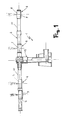
- the device for the delivery of a fluid to be frozen includes a rod, globally referred to as 2, spraying a fluid and more precisely drinking water below an evaporator of a well-known type and not shown in the drawings.
- the spraying rod has drive means and more precisely an opening 3 as it will be better specified hereinafter.
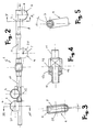
- spray nozzles each one referred to as 4, to spray the fluid on the evaporator, that is not shown in the figure as already said, which have a self-cleaning chamber each, that is generally referred to as 5, being associated to the rod and communicating with its internal portion.
- the self-cleaning chambers 5 vary their inclination, relatively to the rotation plane of the spraying rod, in relation to their distance from the axis of rotation of the same.
- the difference in the inclination of the self-cleaning chambers 5 is determined by the fact that, according to their distance from the axis of rotation, their angular velocity varies together with the spraying rod and, therefore, it is necessary that the fluid flush outcoming from the holes 20 be more inclined towards the rod end and less inclined close to the axis of rotation of the spraying rod so that it can hit by a right angle the evaporator which, otherwise, would not be influenced in the best way by the fluid spray.
- the self-cleaning chambers 5, 6 7 and 8 have a substantially cylindrical configuration in which the spray nozzle 4, defined by the hole 20, is positioned towards the evaporator while, on the opposite side of said hole, the self-cleaning chambers have a closing disc 9, that is advantageously removable, to allow their internal inspection and to remove any scale formations produced on their internal surfaces.
- the sum of the distances of a first pair of chambers from the axis of rotation of the spraying rod is equal to the sum of the distance, still from the axis of rotation, of the second pair of self-cleaning chambers 7 and 8 associated to the second arm 11 of the spraying rod.
- the latter In order that the fluid passing inside the two arms 10 and 11 penetrate easily and in a sufficient amount inside each self-cleaning chamber, the latter have a portion 12 each developing inside the two arms 10 and 11 substantially up to the axis of the spraying rod.
- the special location of the self-cleaning chambers on the spraying rod allows to hit, by means of the spray outcoming from the holes 20, a surface having a longitudinal amplitude substantially equal to the length of one of the two arms 10 or 11 so to hit a surface of the evaporator equivalent to a circumference having a diameter substantially equal to the sum of the length of the two arms.
- the rotation of the spraying rod is obtained thanks to the presence thereon of the opening 3 having substantially a diameter equal to the diameter of the holes 20 of the self-cleaning chambers.
- the distance of the opening 3 from the axis of rotation of the spraying rod depends on the diameter of the opening 3 and on the pressure at which the fluid is introduced in the spraying rod.
- the opening 3 has an inclination relatively to the rod rotational plane so that the component of the propulsion force guarantees to the rod an ideal speed of rotation according to the required needs.
- the spraying rod has two opposing bushes 13 co-axially to its axis of rotation, which are provided with their respective seats 14 each being designed to hold a seal for the hydraulic seal with the rod holding element, generally referred to as 15.
- the plane of emission of the ice cubes from the equipment is substantially inclined relatively to the plane of rotation of the rod so that the latter slide by their own motion on the same without being driven by additional members which might cause chipping.
- the fluid Thanks to the existence of portions 12 developing inside the first and the second arm of the spraying rod, the fluid enters each self-cleaning chamber and therefrom, with a vortical motion, it comes out of the hole 20 to hit the evaporator located over the spraying rod.
- the latter will be perfectly balanced and moreover it will allow the evaporator to be hit on a surface equal to a circumference having a diameter substantially equal to the sum of the length of the two arms 10 and 11.
- the device according to the invention is extremely advantageous to allow the spraying rod to be driven without using for this reason any additional member such as, for example, a gearmotor or a fork for motion transmission as the same fluid penetrating the spraying rod and designed to create the sprays hitting the evaporator provokes by means of the opening 3 the rotation of the same around its fulcrum axis.
- any additional member such as, for example, a gearmotor or a fork for motion transmission as the same fluid penetrating the spraying rod and designed to create the sprays hitting the evaporator provokes by means of the opening 3 the rotation of the same around its fulcrum axis.
- the materials used as well as the size can be of any type according to the needs and to the state of the art.
Landscapes
- Engineering & Computer Science (AREA)
- Physics & Mathematics (AREA)
- Mechanical Engineering (AREA)
- Thermal Sciences (AREA)
- General Engineering & Computer Science (AREA)
- Confectionery (AREA)
- Formation And Processing Of Food Products (AREA)
Applications Claiming Priority (2)
| Application Number | Priority Date | Filing Date | Title |
|---|---|---|---|
| IT2000687 | 1987-04-07 | ||
| IT20006/87A IT1203447B (it) | 1987-04-07 | 1987-04-07 | Dispositivo per l'erogazione di un fluido da ghiacciare in apparecchiature per la formazione di cubetti di ghiaccio |
Publications (2)
| Publication Number | Publication Date |
|---|---|
| EP0286603A2 true EP0286603A2 (de) | 1988-10-12 |
| EP0286603A3 EP0286603A3 (de) | 1991-05-08 |
Family
ID=11163054
Family Applications (1)
| Application Number | Title | Priority Date | Filing Date |
|---|---|---|---|
| EP19880830125 Withdrawn EP0286603A3 (de) | 1987-04-07 | 1988-03-28 | Vorrichtung zur Abgabe einer zu gefrierenden Flüssigkeit in einer Anlage zur Herstellung von Eiswürfeln |
Country Status (9)
| Country | Link |
|---|---|
| US (1) | US4856712A (de) |
| EP (1) | EP0286603A3 (de) |
| JP (1) | JPS6419274A (de) |
| DK (1) | DK127488A (de) |
| FI (1) | FI881249L (de) |
| IT (1) | IT1203447B (de) |
| NO (1) | NO881065L (de) |
| TN (1) | TNSN88029A1 (de) |
| YU (1) | YU60988A (de) |
Cited By (2)
| Publication number | Priority date | Publication date | Assignee | Title |
|---|---|---|---|---|
| CN102853604A (zh) * | 2012-09-10 | 2013-01-02 | 青岛澳润商用设备有限公司 | 制冰机的淋水器 |
| CN108413669A (zh) * | 2017-10-26 | 2018-08-17 | 黄石巨兴达能源环保设备有限公司 | 一种可自动清洗和过滤冰晶的动态冰浆自循环系统 |
Families Citing this family (1)
| Publication number | Priority date | Publication date | Assignee | Title |
|---|---|---|---|---|
| CA2139080C (en) * | 1994-12-23 | 2007-03-13 | Richard Werner | Snow gun |
Family Cites Families (18)
| Publication number | Priority date | Publication date | Assignee | Title |
|---|---|---|---|---|
| US911717A (en) * | 1908-10-12 | 1909-02-09 | Allen W D Mfg Co | Sprinkler-head. |
| US1180526A (en) * | 1915-12-08 | 1916-04-25 | James H Payne | Sprinkler. |
| US1430620A (en) * | 1917-04-30 | 1922-10-03 | Brauer Serena Dorathea | Sprinkling nozzle |
| US1363703A (en) * | 1918-06-15 | 1920-12-28 | G A Buhl Company | Atomizing-nozzle |
| US2409371A (en) * | 1943-11-08 | 1946-10-15 | Marley Company Inc | Multipart distribution nozzle |
| US2644720A (en) * | 1949-12-16 | 1953-07-07 | Clifford H Carr | Insert nozzle |
| US2960990A (en) * | 1956-01-26 | 1960-11-22 | Whirlpool Co | One level dishwasher |
| US3062018A (en) * | 1961-01-30 | 1962-11-06 | Jess F Baker | Method and apparatus for defrosting ice cubing machines |
| BE628401A (de) * | 1962-02-15 | |||
| AT237372B (de) * | 1962-10-15 | 1964-12-10 | Anton Draxler | Rotierender auf einem Stativ aufgebauter Regner |
| US3254501A (en) * | 1963-01-09 | 1966-06-07 | Borg Warner | Automatic ice cube maker |
| US3253784A (en) * | 1964-04-22 | 1966-05-31 | Westinghouse Electric Corp | Dishwasher |
| US3342421A (en) * | 1965-07-28 | 1967-09-19 | Westinghouse Electric Corp | Vortex jet for dishwashers |
| US3550859A (en) * | 1968-07-31 | 1970-12-29 | Herlon Ind Inc | Sprinkler apparatus |
| US3642207A (en) * | 1969-12-30 | 1972-02-15 | Fmc Corp | Rotary sprayer for washing machine |
| US3791163A (en) * | 1971-10-18 | 1974-02-12 | King Seeley Thermos Co | Ice making machine |
| US4272025A (en) * | 1979-05-21 | 1981-06-09 | Ermanno Mazzotti | Water distribution system for an ice making device |
| US4418868A (en) * | 1981-05-29 | 1983-12-06 | Whirlpool Corporation | Dishwasher upper spray arm |
-
1987
- 1987-04-07 IT IT20006/87A patent/IT1203447B/it active
-
1988
- 1988-03-09 DK DK127488A patent/DK127488A/da not_active Application Discontinuation
- 1988-03-10 NO NO881065A patent/NO881065L/no unknown
- 1988-03-16 FI FI881249A patent/FI881249L/fi not_active IP Right Cessation
- 1988-03-23 US US07/172,020 patent/US4856712A/en not_active Expired - Fee Related
- 1988-03-25 YU YU00609/88A patent/YU60988A/xx unknown
- 1988-03-28 EP EP19880830125 patent/EP0286603A3/de not_active Withdrawn
- 1988-04-05 JP JP63082388A patent/JPS6419274A/ja active Pending
- 1988-04-07 TN TNTNSN88029A patent/TNSN88029A1/fr unknown
Cited By (3)
| Publication number | Priority date | Publication date | Assignee | Title |
|---|---|---|---|---|
| CN102853604A (zh) * | 2012-09-10 | 2013-01-02 | 青岛澳润商用设备有限公司 | 制冰机的淋水器 |
| CN108413669A (zh) * | 2017-10-26 | 2018-08-17 | 黄石巨兴达能源环保设备有限公司 | 一种可自动清洗和过滤冰晶的动态冰浆自循环系统 |
| CN108413669B (zh) * | 2017-10-26 | 2020-07-14 | 黄石巨兴达能源环保设备有限公司 | 一种可自动清洗和过滤冰晶的动态冰浆自循环系统 |
Also Published As
| Publication number | Publication date |
|---|---|
| DK127488A (da) | 1988-10-08 |
| NO881065D0 (no) | 1988-03-10 |
| IT8720006A0 (it) | 1987-04-07 |
| US4856712A (en) | 1989-08-15 |
| YU60988A (en) | 1991-04-30 |
| DK127488D0 (da) | 1988-03-09 |
| JPS6419274A (en) | 1989-01-23 |
| IT1203447B (it) | 1989-02-15 |
| NO881065L (no) | 1988-10-10 |
| EP0286603A3 (de) | 1991-05-08 |
| FI881249A7 (fi) | 1988-10-08 |
| FI881249L (fi) | 1988-10-08 |
| FI881249A0 (fi) | 1988-03-16 |
| TNSN88029A1 (fr) | 1990-07-10 |
Similar Documents
| Publication | Publication Date | Title |
|---|---|---|
| US4083074A (en) | Multipurpose pipeline pig | |
| US4346609A (en) | Fluid sampling device | |
| US6481987B2 (en) | Travelling valve for a pumping apparatus | |
| JPH0442068B2 (de) | ||
| KR900010270A (ko) | 공구구동용 진동성 구동장치 | |
| KR970701665A (ko) | 마모 저항 타일이 피복된 원심 분리기 컨베이어(Tile surfacing for a centrifuge conveyor) | |
| EP0286603A2 (de) | Vorrichtung zur Abgabe einer zu gefrierenden Flüssigkeit in einer Anlage zur Herstellung von Eiswürfeln | |
| US3764073A (en) | Sprinkler head mounting means | |
| JPH01502105A (ja) | 風防清掃システム | |
| US3625425A (en) | Tank washers | |
| US3301489A (en) | Combination irrigator and fluid conduit adapter | |
| US5979791A (en) | Intermittant water jet | |
| US3273592A (en) | Deubler etal rotating union control valve | |
| US4732325A (en) | Apparatus for cleaning surfaces | |
| US4234126A (en) | Balanced, reaction impact sprinkler | |
| US4251192A (en) | Rotary pump with symmetrical by-pass and rotor with resiliently mounted vanes | |
| US3507475A (en) | Faucet valve | |
| US1791222A (en) | Sprinkling device | |
| US4624411A (en) | Self-propelled, rotary, liquid atomizer | |
| US1073824A (en) | Water-wheel. | |
| US4311350A (en) | Lubrication system for a thrust bearing | |
| EP0246032A2 (de) | Sprühvorrichtung und -system | |
| US3078045A (en) | Water sprinkler | |
| US1834118A (en) | Sprinkler | |
| RU97103474A (ru) | Заслонка поворотная дисковая |
Legal Events
| Date | Code | Title | Description |
|---|---|---|---|
| PUAI | Public reference made under article 153(3) epc to a published international application that has entered the european phase |
Free format text: ORIGINAL CODE: 0009012 |
|
| AK | Designated contracting states |
Kind code of ref document: A2 Designated state(s): CH DE ES FR GB LI SE |
|
| PUAL | Search report despatched |
Free format text: ORIGINAL CODE: 0009013 |
|
| AK | Designated contracting states |
Kind code of ref document: A3 Designated state(s): CH DE ES FR GB LI SE |
|
| 17P | Request for examination filed |
Effective date: 19911104 |
|
| 17Q | First examination report despatched |
Effective date: 19920430 |
|
| STAA | Information on the status of an ep patent application or granted ep patent |
Free format text: STATUS: THE APPLICATION IS DEEMED TO BE WITHDRAWN |
|
| 18D | Application deemed to be withdrawn |
Effective date: 19920911 |