EP0286764A1 - Transportsystem für Fertighäuser, Fertighaus mit Vorrichtungen für sein Transport und Fertigungsverfahren für ein solches Haus - Google Patents
Transportsystem für Fertighäuser, Fertighaus mit Vorrichtungen für sein Transport und Fertigungsverfahren für ein solches Haus Download PDFInfo
- Publication number
- EP0286764A1 EP0286764A1 EP87450006A EP87450006A EP0286764A1 EP 0286764 A1 EP0286764 A1 EP 0286764A1 EP 87450006 A EP87450006 A EP 87450006A EP 87450006 A EP87450006 A EP 87450006A EP 0286764 A1 EP0286764 A1 EP 0286764A1
- Authority
- EP
- European Patent Office
- Prior art keywords
- house
- transport
- prefabricated
- chassis
- horizontal
- Prior art date
- Legal status (The legal status is an assumption and is not a legal conclusion. Google has not performed a legal analysis and makes no representation as to the accuracy of the status listed.)
- Withdrawn
Links
- 238000004519 manufacturing process Methods 0.000 title claims abstract description 12
- 238000000034 method Methods 0.000 claims abstract description 20
- 239000002184 metal Substances 0.000 claims abstract description 12
- 238000004873 anchoring Methods 0.000 claims abstract description 6
- 238000005192 partition Methods 0.000 claims abstract description 5
- 239000012530 fluid Substances 0.000 claims description 5
- 238000009417 prefabrication Methods 0.000 claims description 5
- 238000005096 rolling process Methods 0.000 claims description 4
- 230000000903 blocking effect Effects 0.000 claims description 3
- 230000008878 coupling Effects 0.000 claims description 3
- 238000010168 coupling process Methods 0.000 claims description 3
- 238000005859 coupling reaction Methods 0.000 claims description 3
- 238000002513 implantation Methods 0.000 claims description 2
- 238000005266 casting Methods 0.000 abstract description 3
- 230000032258 transport Effects 0.000 description 50
- 230000008901 benefit Effects 0.000 description 4
- 238000010276 construction Methods 0.000 description 4
- 230000008569 process Effects 0.000 description 4
- 230000005540 biological transmission Effects 0.000 description 2
- 238000009434 installation Methods 0.000 description 2
- 230000002787 reinforcement Effects 0.000 description 2
- 230000009471 action Effects 0.000 description 1
- 239000011248 coating agent Substances 0.000 description 1
- 238000000576 coating method Methods 0.000 description 1
- 230000006866 deterioration Effects 0.000 description 1
- 238000009415 formwork Methods 0.000 description 1
- 235000000396 iron Nutrition 0.000 description 1
- 239000007788 liquid Substances 0.000 description 1
- 210000000056 organ Anatomy 0.000 description 1
- 230000003014 reinforcing effect Effects 0.000 description 1
- 238000009877 rendering Methods 0.000 description 1
- 239000002689 soil Substances 0.000 description 1
- 229920002994 synthetic fiber Polymers 0.000 description 1
Images



Classifications
-
- B—PERFORMING OPERATIONS; TRANSPORTING
- B62—LAND VEHICLES FOR TRAVELLING OTHERWISE THAN ON RAILS
- B62D—MOTOR VEHICLES; TRAILERS
- B62D53/00—Tractor-trailer combinations; Road trains
- B62D53/04—Tractor-trailer combinations; Road trains comprising a vehicle carrying an essential part of the other vehicle's load by having supporting means for the front or rear part of the other vehicle
- B62D53/06—Semi-trailers
- B62D53/067—Multi-purpose, convertible or extendable load surface semi-trailers
-
- B—PERFORMING OPERATIONS; TRANSPORTING
- B60—VEHICLES IN GENERAL
- B60P—VEHICLES ADAPTED FOR LOAD TRANSPORTATION OR TO TRANSPORT, TO CARRY, OR TO COMPRISE SPECIAL LOADS OR OBJECTS
- B60P3/00—Vehicles adapted to transport, to carry or to comprise special loads or objects
-
- B—PERFORMING OPERATIONS; TRANSPORTING
- B62—LAND VEHICLES FOR TRAVELLING OTHERWISE THAN ON RAILS
- B62D—MOTOR VEHICLES; TRAILERS
- B62D55/00—Endless track vehicles
- B62D55/06—Endless track vehicles with tracks without ground wheels
- B62D55/062—Tracked vehicles of great dimensions adapted for moving bulky loads or gear
Definitions
- the present invention relates to a transport assembly of prefabricated houses, prefabricated house provided with arrangements for its transport and a method of manufacturing such a house.
- the platform of this type of transport vehicle is approximately 80 cm above the ground.
- the height of the house that can be transported is therefore limited to 4.5 meters.
- To facilitate the transport of the house between the place of manufacture and the place of establishment it appeared useful to design a transport unit which offers the advantage of being able to bring such houses to landlocked places of establishment and / or with loose soil. It also appeared useful to design a transport assembly capable of transporting houses of greater heights.
- the transport assembly consists of a first means of transporting the house between the place of manufacture and a place located near the site of establishment and a second means of transport of small size suitable for transport the house to its location.
- the transport assembly for the transport of prefabricated houses from the place of prefabrication to the site of implantation, comprising a first means of transport of the semi-trailer type, and a second means of transport of small size; the said means of transport being constituted by a porous structure teuse hitched to a tractor vehicle is essentially characterized in that the carrying structure, intended to receive the house to be transported, is constituted by a first chassis 4 or front chassis comprising members for coupling to the tractor vehicle by a second chassis 5 or chassis rear comprising a running gear, by at least two horizontal beams 3 parallel to the direction of advance of the towing vehicle, each cooperating in lateral sliding with the first and second chassis and each provided with support members 6 of the house to be transported , and by drive members 7 fixed to said beams and said chassis to bring the latter closer to one another so that they come to grip the house and that their support members 6 are engaged in and / or under the said house, or to separate said beams from each other so as to free the house.
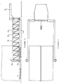
- the second means of transport is constituted by a tracked vehicle 28 provided with an upper plate 29, horizontal orientable in the horizontal plane on which the house is placed.
- the rear chassis of the first means of transport is removable and the beams 3 are each equipped, at the rear end, with a stand 24 provided with a rolling member 25.
- the method of manufacturing small buildings according to the invention from prefabricated components is essentially characterized in that it consists in erecting in the factory prefabricated panels constituting the external walls of the building, to assemble these different panels to each other, to pour, after placing a frame in the space delimited by the panels, a concrete screed, to attach to the panels constituting the exterior walls, second panels constituting the internal partitions, then in a final step to install the roofing elements.
- This manufacturing method has the advantage of concentrating on a manufacturing unit all the personnel necessary for the construction of buildings and of using this personnel also for the prefabrication of the necessary components.
- the construction of a building is carried out sheltered from the weather.
- the method according to the invention consists beforehand in the pouring operation of the screed, in coating the slab on which the said screed is poured with an interface, for example a layer of a viscous liquid to allow thereafter removal from the house.
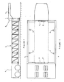
- the transport assembly comprises a first means of transport 1 of the semi-trailer type and a second means of transport 2 of small size.
- the first means of transport is used to transport the house, from its place of prefabrication, near the site of establishment, while the second means of transport is used to bring the house to its place of establishment.
- the first means of transport 1 comprises a tractor unit to which is attached a carrying structure receiving the house to be transported.
- This supporting structure is constituted by a chassis 4 or front chassis, comprising members for coupling to the towing vehicle, by a second chassis or rear chassis 5 comprising a running gear, by at least two horizontal beams 3, parallel to the direction of advancement of the towing vehicle each cooperating in lateral sliding with the first and second chassis and each provided with support members 6 of the house to be transported, and by drive members 7 fixed to said beams and said chassis to bring said beams 3 together one of the other so that they enclose the house and that the support members 6 are engaged in and / or under the latter and to separate the said beams from one another so as to free the house .
- the first chassis 4 or front chassis comprises a vertical frame 8 transverse to the direction of advance of the tractor vehicle and a horizontal plate 9 which cooperates in articulation with the seat of the tractor vehicle.
- the frame 8 of the front chassis consists of two vertical metal uprights 10 joined at the upper end by the anchoring plate 9 to the towing vehicle. The two amounts are also joined to each other by two horizontal metal crosspieces, a central crosspiece 11 and a lower crosspiece 12.
- the second rear chassis also comprises a vertical frame 13 transverse to the direction of advance of the means of transport, formed by the assembly of two vertical uprights 14 joined by an upper horizontal cross member 15 and by a horizontal lower cross member 16.
- each beam 3 of the supporting structure each cooperate at their end in lateral sliding with the crosspieces of the first and second chassis.
- each beam 3 at each end comprises two parallel sheaths 17, superimposed, perpendicular to the longitudinal axis of said beam, which are each engaged in sliding on the corresponding crosspiece.
- Each end of the beam cooperates with at least one drive member 7.
- This motor member preferably constituted by a hydraulic cylinder is fixed by its rod fixed to one of the sheaths of the beam and by its body to a yoke fixed on the crosspiece engaged in said sheath.
- each motor member or hydraulic cylinders are connected to a hydraulic circuit comprising at least one manually actuated hydraulic distributor which directs the hydraulic flow, either in the rear chamber of each cylinder, or in the front chamber so as to bring each beam closer together. the other or, on the contrary, discard it.
- the end of each beam cooperates with two jacks 7, each of these jacks being fixed by its rod on a sheath 17.
- the jacks at each end of the beam are hydraustically balanced.
- each beam 3 is constituted by two parallel, horizontal beams, an upper beam 18 and a lower beam 19, joined to each other at each end by a vertical upright. Furthermore, these two beams are joined by vertical struts 20 and by oblique struts so as to form a lattice assembly.
- each beam 3 is equipped with support members 6, these said members being preferably fixed to the lower beam 13.
- the support members 6 of the house each consist of a spindle embedded by one of its ends in the lower spar of the corresponding beam, said spindle projecting towards the other beam and developing perpendicularly area in relation to its spar.
- Each beam 3 is equipped with two pins 6 which are each axially aligned with one of the pins of the other beam.
- the slab constituting the floor of the house is pierced with horizontal holes.
- the slab constituting the floor of the house and / or the bottom of the panels constituting the walls is or are equipped with orifices 22 reinforced by tubular elements 23, horizontal, metallic.
- tubular elements 23 are embedded in the concrete of the slab and / or of the panels and are flush with the lateral faces of the slab and / or are flush with the lower part of the exterior faces of the panels.
- the support members consist of metallic, horizontal plates fixed against the lower spar. These plates are intended to be engaged under the slab constituting the floor of the house.
- each beam 3 is equipped with support members, some of which are constituted by pins and the others of which are constituted by plates.
- the rear frame 5 of said structure is removable while the rear end of each beam 3 is equipped with a retractable stand 24 terminated by a rolling member 25 .
- the support structure following a backward movement, can be engaged around a house to be transported maintained above by wedges. Subsequently after installation of the rear chassis and removal of the crutches, the beams 3 via the drive members are brought into pressure against the house while their support members are engaged in the orifices of the slab. To remove the house from the support structure, the reverse operation is practiced.
- the sleeves 17 which cooperate with the upper and lower crosspieces of the frame of the rear chassis each receive in fixing a horizontal sleeve 25 parallel to the advancement axis of the conveyor and the rear end of each beam is equipped of two horizontal pins 26 intended to engage and lock in the corresponding sleeve.
- the pins 26 extend axially rearward the beams of the beam.
- one or more removable pins 27 are provided which are intended to be engaged in transverse orifices made in the sleeve 25 and in the spindle 26. It is obvious that any other locking mode can be used.
- each stand comprises a vertical sheath fixed by any known means to the side members of the corresponding beam and a screw and nut system which actuates a vertical foot slidably mounted in the sheath.
- This vertical leg is terminated by a yoke which receives the rolling member.
- the sheath and the foot both have a polygonal cross section to avoid rotation of said foot relative to said sheath.
- the screw of the screw and nut system is locked in translation in the sleeve.
- This upper end screw is equipped with a crank. At the lower end, the screw is engaged in an axial thread made in the foot. It is understood that the action on the crank causes the downward movement of the foot or the upward movement according to the direction of rotation.
- the second means of transport 2 is a small vehicle comprising tracks 28, and a horizontal upper plate 29 intended to receive the house.
- the tracks of the second means of transport are mechanically associated with a heat engine via an appropriate transmission comprising in particular a gearbox.
- the second means of transport is equipped with a handle at the end free unit of which is mounted a dashboard with different controls.
- the second means of transport After stalling the house in height and removing the first means of transport, the second means of transport is engaged under the house. This second means of transport can then bring the house to its location.
- the upper plate of the second means of transport can be oriented in a horizontal plane.
- the plate 29 is carried by a vertical pivot movable in rotation about a vertical axis.
- This pivot is connected, via an appropriate transmission to a drive member.
- This drive member is controlled from control members mounted on the dashboard of the second means of transport.
- removable base members are provided, the role of which is to lift the house to take it off the shelf 29.
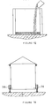
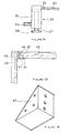
- These legs are lateral to the house and are for example each constituted by a hydraulic cylinder whose body has a radial finger 32 intended to be engaged in the orifice 22 of one of the tubular elements 23 and whose rod projecting towards the bottom is terminated by a support plate on the floor.
- such a member 32 can be used note ment to raise the house on the place of manufacture to have wedges under the slab of said house.
- Such members can also be used to keep the house at a distance from the ground when the second means of transport is engaged under the latter.
- the members 31 can be held in place against the house during the transport of the latter by the second means. In this way these organs oppose the accidental tilting of the house.
- the transport assembly as described allows the transport of a prefabricated house at a lower cost.
- the following method of building a transportable house is given by way of example.
- the object of the process according to the invention is to construct small buildings from prefabricated components, in particular from panels 33 of exterior walls and roofing elements.
- the method according to the invention consists in erecting the panels 33 constituting the exterior walls on a pouring area D and then assembling these panels to one another.
- an interface which can be a viscous fluid is affixed to the pouring area D.
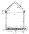
- the reinforcement 34 intended for the rendering of the slab 35 constituting the floor of the said building is introduced and placed in the building, and the elements of anchoring of the lifting means. It should be noted that the reinforcement 34 of the slab is prefabricated and is introduced in one piece into the building.
- the concrete is poured from the slab, this operation being carried out from above. It is understood that the lower zones of the panels 33 constitute a formwork. It is also understood that the concrete of the slab 35 cannot adhere to the surface of the pouring area owing to the fact that the latter is coated with a release fluid or any other interface.
- the process consists in placing and fixing the panels constituting the internal partitions and walls of the building and mounting the necessary equipment in this building.
- the process consists in placing on the exterior walls of the building a fully prefabricated roof or according to another embodiment, to lay and assemble between them and to said panels the components of the roof of the building.
- a lifting means 36 is put in place to remove the building from the pouring area D.
- these lifting means are of the same type as those previously described.
- these lifting means may be constituted by a hydraulic cylinder whose body 55 is provided with a radial finger 56 coming to engage in the orifice 22 and whose rod 57 is terminated by a plate 58 of support on the ground .
- the body 55 of this jack is provided with an orifice which opens into its rear chamber.
- This orifice is equipped with a connector 59 which is connected to a hydraulic line 60 of a high pressure hydraulic circuit which distributes hydraulic fluid in said chamber to move the piston and lift the house.
- the panels 33 of the exterior wall are made of reinforced molded concrete. These panels comprising at the lower end a series of horizontal irons 37 waiting to be fixed to the frame 2 of the yoke 3 and to be embedded in the concrete of the latter.
- Each panel has assembly or blocking members 38 to an adjoining panel. These assembly members are preferably fixed on the face interior of each panel near their vertical bank.
- these assembly or blocking members each consist of a rectangular metal plate arranged on the inner face of the panel so that one of its vertical edges come at the edge of the panel.
- the plate 38 of one comes to extend the plate of the other.
- these two plates are welded to each other to carry out the assembly of the panels.
- each plate 38 is mounted in a reservation of the panel so as to prevent them from projecting from the interior face of said panel. It is obvious that any other method or fixing device may be used.
- each panel has a transverse orifice 22 of circular cross section which constitutes an anchor point for the lifting elements 36 of the house.
- this orifice is reinforced by a tubular reinforcing element 23 to avoid deterioration of the panel, at the level of the orifice during the lifting operation.
- the orifice (s) of a panel are axially aligned with the orifices of the opposite panel and the orifices arranged along the same axis receive the end of the same tubular element put in place before or during casting of the slab. In this way, the tubular element, running from a panel to the other strengthens the mechanical characteristics of the screed.
- Each panel is furthermore equipped with threaded bushings on standby intended for fixing internal partitions for example or else for fixing construction equipment.
- the walls of the building are each constituted by the same panel, but it is obvious that each wall of the building can be constituted by the juxtaposition of several panels.
- the dimensions of the panels constituting the exterior walls are multiples of a basic module whose value is for example 30 cms. It should also be noted that the tubular elements develop in the screed of the building transversely to the longest walls of the building and that these walls are equipped with the orifices for receiving the tubular elements.
- the upper end of the exterior walls of the building receives the framework of the roof.
- the panels constituting the exterior walls are each equipped at the upper end with one or more shoes 41 for anchoring horizontal beams 42 supporting the frame.
- These anchoring shoes 41 are removably fixed by any known means at the upper end of the panels against their inner face.
- the shoes are fixed by screwing.
- Each shoe preferably metallic, has a support wall 43 against the inner face of the panel and at least two walls perpendicular to each other and to the support wall.
- the horizontal wall receives the end of the beam which is fixed by bolting against the vertical wall 45.
- this vertical wall 45 is pierced with at least two transverse orifices 46, aligned along the same vertical axis. These transverse holes receive the beam fixing bolts.
- the exterior walls 1 of the building receive a completely prefabricated roof 47.
- This roof comprises a horizontal metal frame 48 which bears on the horizontal upper bank of the exterior walls of the building and covers the latter.
- the longitudinal members and crosspieces of this metallic frame consist of metallic profiles comprising a horizontal wing 49 bearing on the horizontal upper bank of the outer wall and at least one vertical wing 50 projecting downwards.
- the vertical wing 50 of the metal frame is arranged either outside or inside the building and has the role of ensuring the wedging of the roof along a longitudinal and transverse axis to the building.
- the metal profiles constituting the support frame of the roof each comprise two vertical downwardly projecting wings connected to a central core so that their cross section is in the form of a "U" facing downwards.
- the profiles of the lower frame each overlap the corresponding upper edge.
- the prefabricated roof is fixed by the frame to the horizontal upper edge of each exterior wall.
- the wing 49 of each profile is pierced with a series of transverse orifices which each come during assembly to be arranged in the axis of a threaded orifice made in a vertical socket 51 embedded in the concrete of the panel constituting the exterior wall and flush with the horizontal upper bank of this panel.
- screws 52 are provided, each engaged in the tapped orifice of one of the sockets through the orifice of the profile core.
- the lower frame of the roof due to its rigidity, also ensures the belting of the house.
- On the metal frame of the roof are fixed by any known means the farm (s) 53 of the roof.
- These trusses are for example formed by two legs inclined towards one another which carry at the upper end a ridge beam.
- the roof frame is equipped with edge boards 54. These edge boards are fixed in known manner to the outer wings of the frame and completely cover the latter.
- the prefabricated roof has one or more lifting points fixed for example to the elements of the farm or to the ridge beam.
- lifting jacks 36 are hydraustically balanced.
- the method and the components as described are mainly suitable for the manufacture of small dwelling houses easily transportable by road by the transport assembly which is the subject of this patent.
Landscapes
- Engineering & Computer Science (AREA)
- Transportation (AREA)
- Mechanical Engineering (AREA)
- Chemical & Material Sciences (AREA)
- Combustion & Propulsion (AREA)
- Health & Medical Sciences (AREA)
- Public Health (AREA)
- Conveying And Assembling Of Building Elements In Situ (AREA)
Priority Applications (2)
| Application Number | Priority Date | Filing Date | Title |
|---|---|---|---|
| FR8518644A FR2591544B1 (fr) | 1985-12-13 | 1985-12-13 | Ensemble de transport de maison prefabriquee et maison prefabriquee dotee d'amenagements pour son transport. |
| EP87450006A EP0286764A1 (de) | 1987-04-03 | 1987-04-03 | Transportsystem für Fertighäuser, Fertighaus mit Vorrichtungen für sein Transport und Fertigungsverfahren für ein solches Haus |
Applications Claiming Priority (1)
| Application Number | Priority Date | Filing Date | Title |
|---|---|---|---|
| EP87450006A EP0286764A1 (de) | 1987-04-03 | 1987-04-03 | Transportsystem für Fertighäuser, Fertighaus mit Vorrichtungen für sein Transport und Fertigungsverfahren für ein solches Haus |
Publications (1)
| Publication Number | Publication Date |
|---|---|
| EP0286764A1 true EP0286764A1 (de) | 1988-10-19 |
Family
ID=8198314
Family Applications (1)
| Application Number | Title | Priority Date | Filing Date |
|---|---|---|---|
| EP87450006A Withdrawn EP0286764A1 (de) | 1985-12-13 | 1987-04-03 | Transportsystem für Fertighäuser, Fertighaus mit Vorrichtungen für sein Transport und Fertigungsverfahren für ein solches Haus |
Country Status (1)
| Country | Link |
|---|---|
| EP (1) | EP0286764A1 (de) |
Cited By (4)
| Publication number | Priority date | Publication date | Assignee | Title |
|---|---|---|---|---|
| AU708099B2 (en) * | 1995-06-07 | 1999-07-29 | Gambro Inc | Extracorporeal blood processing methods and apparatus |
| WO2009073696A1 (en) * | 2007-12-04 | 2009-06-11 | Custom Quality Homes L.L.C. | Transport vehicle having tension/compression system |
| CN101793099A (zh) * | 2010-03-26 | 2010-08-04 | 董兰田 | 建筑物整体平移托板履带车 |
| CN111775810A (zh) * | 2020-07-30 | 2020-10-16 | 大禾众邦(厦门)智能科技股份有限公司 | 一种轻钢房屋速建车 |
Citations (5)
| Publication number | Priority date | Publication date | Assignee | Title |
|---|---|---|---|---|
| US2463647A (en) * | 1947-09-30 | 1949-03-08 | Schuette Earl | House moving trailer |
| US2788145A (en) * | 1955-03-10 | 1957-04-09 | Walter G Clark | House moving trailer |
| US3330574A (en) * | 1965-07-21 | 1967-07-11 | Rogers Brothers Corp | Ground loading trailer with laterally extensible load supporting bed |
| US3450283A (en) * | 1967-05-02 | 1969-06-17 | Henry C Helland | Trailer with detachable rear wheels |
| FR2583083A1 (fr) * | 1985-06-07 | 1986-12-12 | Mereu Jean Charles | Batiment en dur, de style traditionnel, destine a l'habitation, et livre acheve en un bloc autonome transportable |
-
1987
- 1987-04-03 EP EP87450006A patent/EP0286764A1/de not_active Withdrawn
Patent Citations (5)
| Publication number | Priority date | Publication date | Assignee | Title |
|---|---|---|---|---|
| US2463647A (en) * | 1947-09-30 | 1949-03-08 | Schuette Earl | House moving trailer |
| US2788145A (en) * | 1955-03-10 | 1957-04-09 | Walter G Clark | House moving trailer |
| US3330574A (en) * | 1965-07-21 | 1967-07-11 | Rogers Brothers Corp | Ground loading trailer with laterally extensible load supporting bed |
| US3450283A (en) * | 1967-05-02 | 1969-06-17 | Henry C Helland | Trailer with detachable rear wheels |
| FR2583083A1 (fr) * | 1985-06-07 | 1986-12-12 | Mereu Jean Charles | Batiment en dur, de style traditionnel, destine a l'habitation, et livre acheve en un bloc autonome transportable |
Cited By (4)
| Publication number | Priority date | Publication date | Assignee | Title |
|---|---|---|---|---|
| AU708099B2 (en) * | 1995-06-07 | 1999-07-29 | Gambro Inc | Extracorporeal blood processing methods and apparatus |
| WO2009073696A1 (en) * | 2007-12-04 | 2009-06-11 | Custom Quality Homes L.L.C. | Transport vehicle having tension/compression system |
| CN101793099A (zh) * | 2010-03-26 | 2010-08-04 | 董兰田 | 建筑物整体平移托板履带车 |
| CN111775810A (zh) * | 2020-07-30 | 2020-10-16 | 大禾众邦(厦门)智能科技股份有限公司 | 一种轻钢房屋速建车 |
Similar Documents
| Publication | Publication Date | Title |
|---|---|---|
| EP3745842B1 (de) | Verfahren zur herstellung einer schutzstruktur und kit dafür | |
| CA1328475C (fr) | Element de construction transportable en forme de conteneur | |
| EP0407536B1 (de) | Ausziehbare, starre struktur | |
| EP2021546A1 (de) | Temporäre brücke | |
| CA2238255C (fr) | Dispositif de levage d'une charpente et le cas echeant d'une partie de construction reposant sur cette charpente | |
| FR2999208A1 (fr) | Recette a materiaux comprenant un bati et une plateforme mobile en translation sur le bati entre une position exterieure et une position escamotee | |
| WO2021099593A1 (fr) | Module d'habitation préfabriqué | |
| EP0468827B1 (de) | Bewegliche, schwere, selbständige und selbstaufrichtende Zentrale für die Herstellung von Beton | |
| FR3140386A1 (fr) | Construction, de préférence modulaire, comprenant un châssis de plafond en bois et un châssis de plancher en bois | |
| LU85595A1 (fr) | Element de construction en forme de conteneur transportable et construction formee par assemblage de tels elements | |
| FR2964133A1 (fr) | Dispositif de maintien sur une plate forme d'un mat vertical | |
| WO2021099591A1 (fr) | Procédé de construction d'un bâtiment et systèmes pour sa mise en oeuvre | |
| EP3619379B1 (de) | Satz von strukturelementen zur bildung eines mehrgeschossigen, oberirdischen parkhauses und entsprechendes mehrgeschossiges oberirdisches parkhaus | |
| FR2891854A1 (fr) | Installation a niveaux multiples pour le stationnement automatique de vehicules | |
| EP2711260B1 (de) | Seilbahnstation, insbesondere eines Sesselliftes oder einer Gondelbahn, und Montage- und Demontageverfahren einer solchen Station | |
| FR2591636A1 (fr) | Procede de fabrication de batiment a partir de composants prefabriques, composants prefabriques pour mise en oeuvre du procede et batiment realise | |
| EP0900692B1 (de) | Einheit aus abnehmbarer Karosseriebaugruppe und Trägerfahrzeug, Methode zum Kuppeln einer derartigen Einheit, sowie mit einer solchen Einheit ausgerüstetes Fahrzeug | |
| FR2730513A1 (fr) | Procede de construction d'un sol en beton d'une structure et dispositif utilise pour celui-ci | |
| EP4628667B1 (de) | Konstruktion, vorzugsweise modulares, mit einem holzdeckenrahmen und einem holzbodenrahmen | |
| FR2591544A1 (fr) | Ensemble de transport de maison prefabriquee et maison prefabriquee dotee d'amenagements pour son transport. | |
| FR3160364A1 (fr) | Atelier de maintenance de véhicules mobile | |
| FR2685277A1 (fr) | Vehicule de transport bache. | |
| EP2716495B1 (de) | Bewohnbarer Fertigbau, der auf Rädern bewegbar ist | |
| FR2497746A1 (fr) | Plate-forme pour stations-service destinee a la fixation de pompes de distribution de carburant ou de combustible | |
| CA1279586C (fr) | Element de construction en forme de conteneur transportable et construction formee par assemblage de tels elements |
Legal Events
| Date | Code | Title | Description |
|---|---|---|---|
| PUAI | Public reference made under article 153(3) epc to a published international application that has entered the european phase |
Free format text: ORIGINAL CODE: 0009012 |
|
| AK | Designated contracting states |
Kind code of ref document: A1 Designated state(s): AT BE CH DE ES FR GB GR IT LI LU NL SE |
|
| STAA | Information on the status of an ep patent application or granted ep patent |
Free format text: STATUS: THE APPLICATION IS DEEMED TO BE WITHDRAWN |
|
| 18D | Application deemed to be withdrawn |
Effective date: 19890420 |