EP2711260B1 - Seilbahnstation, insbesondere eines Sesselliftes oder einer Gondelbahn, und Montage- und Demontageverfahren einer solchen Station - Google Patents
Seilbahnstation, insbesondere eines Sesselliftes oder einer Gondelbahn, und Montage- und Demontageverfahren einer solchen Station Download PDFInfo
- Publication number
- EP2711260B1 EP2711260B1 EP13354034.4A EP13354034A EP2711260B1 EP 2711260 B1 EP2711260 B1 EP 2711260B1 EP 13354034 A EP13354034 A EP 13354034A EP 2711260 B1 EP2711260 B1 EP 2711260B1
- Authority
- EP
- European Patent Office
- Prior art keywords
- station
- prefabricated
- support
- assembly
- area
- Prior art date
- Legal status (The legal status is an assumption and is not a legal conclusion. Google has not performed a legal analysis and makes no representation as to the accuracy of the status listed.)
- Not-in-force
Links
- 238000000034 method Methods 0.000 title claims description 31
- 239000004567 concrete Substances 0.000 claims description 62
- 238000004519 manufacturing process Methods 0.000 claims description 25
- 239000004576 sand Substances 0.000 claims description 11
- 238000009417 prefabrication Methods 0.000 claims description 10
- 239000004570 mortar (masonry) Substances 0.000 claims description 8
- 238000003860 storage Methods 0.000 claims description 8
- 238000007789 sealing Methods 0.000 claims description 7
- 238000000151 deposition Methods 0.000 claims description 3
- 230000008021 deposition Effects 0.000 claims description 2
- 238000003825 pressing Methods 0.000 claims 1
- 230000032258 transport Effects 0.000 description 13
- 239000002184 metal Substances 0.000 description 9
- 229910052751 metal Inorganic materials 0.000 description 9
- 238000010276 construction Methods 0.000 description 6
- 238000004873 anchoring Methods 0.000 description 4
- 238000001035 drying Methods 0.000 description 3
- 239000004579 marble Substances 0.000 description 3
- 239000003351 stiffener Substances 0.000 description 3
- XEEYBQQBJWHFJM-UHFFFAOYSA-N Iron Chemical compound [Fe] XEEYBQQBJWHFJM-UHFFFAOYSA-N 0.000 description 2
- 230000003749 cleanliness Effects 0.000 description 2
- 230000001419 dependent effect Effects 0.000 description 1
- 238000006073 displacement reaction Methods 0.000 description 1
- 238000009415 formwork Methods 0.000 description 1
- 238000011065 in-situ storage Methods 0.000 description 1
- 238000009434 installation Methods 0.000 description 1
- 229910052742 iron Inorganic materials 0.000 description 1
- 239000007788 liquid Substances 0.000 description 1
- 230000002787 reinforcement Effects 0.000 description 1
- 238000000926 separation method Methods 0.000 description 1
- 238000009416 shuttering Methods 0.000 description 1
- 239000000725 suspension Substances 0.000 description 1
- 239000002023 wood Substances 0.000 description 1
Images
Classifications
-
- B—PERFORMING OPERATIONS; TRANSPORTING
- B61—RAILWAYS
- B61B—RAILWAY SYSTEMS; EQUIPMENT THEREFOR NOT OTHERWISE PROVIDED FOR
- B61B1/00—General arrangement of stations, platforms, or sidings; Railway networks; Rail vehicle marshalling systems
- B61B1/02—General arrangement of stations and platforms including protection devices for the passengers
-
- B—PERFORMING OPERATIONS; TRANSPORTING
- B61—RAILWAYS
- B61B—RAILWAY SYSTEMS; EQUIPMENT THEREFOR NOT OTHERWISE PROVIDED FOR
- B61B12/00—Component parts, details or accessories not provided for in groups B61B7/00 - B61B11/00
Definitions
- the invention relates to cable car stations, including chairlift or gondola, assembly and disassembly of such a station.
- the French patent application FR 2255200 discloses a station of a chairlift, comprising a metal suspension frame of a pulley.
- the metal frame comprises two triangular piers each having two iron legs assembled in inverted V.
- the bases of the feet are attached to anchor blocks consisting of concrete blocks.
- the French patent application FR2329490 discloses an overground railway station consisting of a single support dock and a light concrete pier platform.
- the platform floor is made of prefabricated elements placed on the edge of longitudinal beams and floor joists.
- the floor may consist of light concrete slabs.
- construction elements made in the form of lightweight construction are delivered as completed parts on site and can be quickly mounted, the support can be transported on a normal truck.
- the document "More transparent, lighter, more aesthetic” discloses a method of constructing a station that can be used for all disengageable systems.
- the station has a uniform supporting structure that rests on two central metal pillars supporting all the rails and synchronization devices.
- the station includes a concrete pillar at the back.
- An object of the invention is to overcome the drawbacks mentioned above, and in particular to provide a method of mounting a cable car station which is fast and which guarantees a mounting of a robust station meeting the required safety standards .
- Another object of the invention is to provide a method of disassembly of a station that allows reuse of the various elements of the dismantled station for reassembly of the station to another location.
- Another object of the invention is to provide a dismountable cable car station in view of going up the station to a new location.
- a method of mounting a cable car station including chairlift or gondola.
- a faster process is provided which is less subject to weather conditions.
- a prefabrication stage supports carried out before the stage of mounting of the station it is no longer necessary to cast the media in place.
- the step of prefabrication of the supports can no longer be subjected to bad weather because the supports are made in an area dedicated to the manufacture of concrete parts, such as a factory or a closed room.
- the prefabrication step may comprise the production of at least one prefabricated support from several distinct parts made of concrete, the transporting step comprising transporting the parts of each prefabricated support from the manufacturing zone to the mounting zone. and the mounting step comprising laying the portions of each prefabricated support at the predetermined location of the ground defining the mounting area.
- the mounting step may comprise a laying of at least two prefabricated supports on said mounting area and an attachment of at least one connecting element on the two prefabricated supports, each prefabricated support being provided with a first fixing means which cooperates with a second fastening means provided on the connecting element.
- Such a connecting element makes it possible to avoid a separation of the supports between them, in particular during the movements of the ground on which the station rests.
- Each prefabricated support may comprise at least one lifting element intended to lift the support during the transport step and during the step of laying the prefabricated supports.
- the mounting step may comprise depositing a bed of sand on the predetermined location of the ground delimiting the mounting area so as to form said mounting area, and laying of each support prefabricated on the deposited sand bed.
- the deposition of a sand bed provides sufficient stability to the station while being less time consuming than concrete cleanliness.
- the assembly step comprises an embodiment of at least one concrete screed on the predetermined location of the ground delimiting the mounting zone so as to form said mounting zone, and a laying of each prefabricated support on said concrete screed made.
- the mounting step comprises an embodiment of at least one concrete screed on the predetermined location of the ground delimiting the mounting zone so as to form said mounting zone, the screed of concrete comprising at least one projecting abutment, and a laying of each prefabricated support on said concrete screed made and bearing against said abutment.
- the mounting step comprises an embodiment of at least one concrete screed on the predetermined location of the ground delimiting the mounting zone, an embodiment of at least one sealing mortar on said concrete screed so as to form said mounting zone, and a laying of each prefabricated support on said sealing mortar produced.
- a cable car station including chairlift or gondola, removable, mounted on a mounting area and comprising at least one prefabricated concrete support for supporting an upper part of the station said prefabricated support being adapted to be transported from the mounting area to a storage area separate from the mounting area.
- the station may comprise at least one prefabricated support comprising several distinct parts made of concrete and able to be transported from the mounting zone to the storage area distinct from the mounting zone.
- the station may comprise at least two prefabricated supports and at least one connecting element fixed on the two prefabricated supports, each prefabricated support being provided with a first fastening means which cooperates with a second fastening means provided on the connecting element. .
- Each prefabricated support may comprise at least one lifting element intended to lift the prefabricated support for its transport.
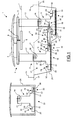
- FIG. 1 schematically shown a station 1 cable car, including chairlift or gondola, removable.
- the station 1 can also be intended for a ski lift or a telecord (also called snow-wire).
- the station 1 comprises an upper part 2 and a lower part 3 on which the upper part 2 rests.
- the upper part 2 comprises a roof 4, a frame 5 to support the roof 4, and a pulley 6 for driving a cable.
- tractor 7 on which are hung vehicles, such as seats or cabins, for the transport of persons or others.
- Station 1 can be a boarding or disembarking station. We have shown on the figure 1 , an embodiment of a station 1 boarding people.
- the boarding station 1 comprises a motor 8 mounted on the frame 5, for driving the pulley 6, in particular via a driving shaft 9.
- the lower part 3 of the station 1 comprises, in turn, at least one prefabricated support 10, 11 for supporting the upper part 2 of the station 1 and at least one pylon 12, 13, each pylon 12, 13 being mounted between a prefabricated support 10, 11 and the frame 5 so as to raise the upper part 2 of the station 1.
- the station 1 comprises two prefabricated supports 10, 11 and two pylons 12, 13.
- the station 1 may comprise one or more prefabricated supports and one or more towers.
- the structure of the station 1 comprising the upper 2 and lower 3 parts, is mounted on a mounting zone 14.
- a mounting zone 14 On the figure 1 two dashed lines referenced 15, 16 are shown, and the mounting zone 14 is between the two lines 15, 16.
- the prefabricated supports 10, 11 are placed at a predetermined location on the ground delimiting the mounting zone 14.
- the ground may be located in the mountains or in the city.
- the mounting area 14 may be integrated within an open or closed building.
- the mounting zone 14 may comprise a pit 17 comprising one or more stages.
- the mounting area 14 comprises a pit 17 having two stages 18, 19 located at different height levels.
- a first stage 18 is located lower than a second stage 19.
- Such an embodiment is particularly suitable for a station 1 boarding a chairlift to be able to clear the skis of people who embark.
- the prefabricated supports 10, 11 are intended to be placed on the predetermined location of the ground forming the mounting zone 14.
- the prefabricated supports 10, 11 can be placed directly on the predetermined location of the ground.
- the prefabricated supports 10, 11 can be placed directly on the bottom of the pit 17 which then forms the mounting zone 14.
- the predetermined location of the ground can be covered in part by a bed of sand 20, and the prefabricated supports 10, 11 are placed on the sand bed 20 which forms the mounting zone 14. It is also possible to consider replacing the sand bed 20 with a screed made of concrete. It is also possible to make several concrete screeds, each concrete screed being intended to receive a prefabricated support 10, 11. Advantageously, each concrete screed is scraped. In addition, it is possible, on the concrete screed, a liquid sealing mortar forming the mounting zone 14, and each prefabricated support is placed on the sealing mortar produced.
- the sealing mortar makes it possible to improve the physical contact of the prefabricated support 10, 11 with the concrete screed.
- the stops allow to maintain in position the prefabricated support 10, 11 with the concrete screed.
- the pit 17 can be filled with fill, earth or rubble, up to the level 21, shown here in dashed line, of the ground 22 next to the mounting zone 14.
- the station 1 is removable, that is to say that the various elements of the station 1 are removable and can be transported from the mounting zone 14 to another zone separate from the mounting zone 14, for example a storage area not shown on the figure 1 for simplification purposes.
- the station 1 is meant by transporting an element of the station 1, a displacement of the element of a first zone to a second distinct zone and in which the integrity of the element is preserved for its reuse in the second zone, for example for a subsequent editing of a new station on this second zone.
- the second zone is located outside the first zone.
- the prefabricated supports 10, 11 are configured to be transported from a first zone, for example from the mounting zone 14, to a second zone distinct from the first zone.
- the prefabricated supports 10, 11 are preferably made of concrete in a manufacturing zone 23 distinct from the mounting zone 14, that is to say that the manufacturing zone 23 is situated outside the mounting zone 14.
- the mounting zone 14 may be located in the open air or not, in the mountains or in the city, and may be more or less distant from the manufacturing zone 23.
- the manufacturing zone 23 may include a room 24 particularly suitable for producing concrete parts.
- the room 24 is a closed room in which the parts to be made are not subjected to bad weather.
- Each prefabricated support 10, 11 comprises a base 25 surmounted by a stiffener 26 to reinforce the support 10, 11 subjected in particular to the load of the upper part 2 of the station 1.
- Each prefabricated support 10, 11 further comprises a base 27 , mounted on the stiffener 26, for receiving a pylon 12, 13.
- Each prefabricated support 10, 11 can be made in one block.
- a prefabricated support 10, 11 may comprise several separate prefabricated concrete parts.
- the base 25, the stiffener 26 and the base 27 can form the distinct parts of a prefabricated support 10, 11.
- the separate parts of a support 10, 11 are made separately, and the prefabricated support 10, 11 is made by an assembly of the aforementioned distinct parts.
- the assembly of the parts of the prefabricated support 10, 11 can be carried out in the manufacturing zone 23, or in the mounting zone 14.
- the prefabricated supports 10, 11 are produced on a non-stick marble placed in the room 24 so as to lift the prefabricated support 10, 11, after drying, for its transport.
- the marble can be wood or metal.
- the marble can also be coated with a non-stick product.
- Each prefabricated support 10, 11 also comprises an anchoring system comprising several anchoring rods 28.
- each prefabricated support 10, 11 comprises a lifting system for transporting and installing the prefabricated support 10, 11.
- the lifting system may comprise a single anchor
- the lifting system comprises a first assembly comprising one or more lifting anchors 29 to support the weight of the prefabricated support 10, 11 during its transport, and a second set comprising other lifting anchors 29 mounted on the support so as to balance it.
- Each prefabricated support 10, 11 may comprise three lifting anchors 29 located in a triangle on the base 25, or four lifting anchors 29 situated at the four corners of the base 25, or a plurality of lifting anchors 29 arranged on the support of to distribute the weight, to ensure both the balancing and the weight support of the prefabricated support 10, 11.
- the lifting anchors 29 are also partially embedded in the concrete support 10, 11.
- each anchor lifting 29 comprises a rod 31 incorporated in the concrete of the support 10, 11 and a head 32, for example spherical or hemispherical, which is not embedded, that is to say which is located outside the prefabricated support 10, 11.
- the heads 32 are intended to cooperate with a lifting ring connected to a hook, cable or chain, to lift the prefabricated support 10, 11 to transport it from one area to another.
- a prefabricated support 10, 11 may have a weight of about 60 tons.
- the lifting system comprises one or more through holes formed in one or more parts of the prefabricated support 10, 11. The through holes are configured for the passage of a metal bar, or a wire rope , to transport the prefabricated support 10, 11.
- each prefabricated support 10, 11 may comprise fixing means 30, and a grounding cable, not shown here for simplification purposes.
- the grounding cable is partially embedded in the concrete of the support 10, 11 so as to connect a metal reinforcement completely embedded in the concrete of the support 10, 11 to a metal carcass of a pylon 12, 13 which is, as for it, connected to the earth.
- the station 1 may further comprise a connecting element 33 fixed on the two prefabricated supports 10, 11 in order, in particular, to prevent the prefabricated supports 10, 11 from moving away from each other.
- the connecting element 33 comprises fastening means 34 intended to cooperate with the means of fastening 30 provided on the prefabricated supports 10, 11.
- the connecting element 33 may comprise a sill 35 made of concrete.
- the fixing means 30 provided on the prefabricated supports 10, 11 may be embedded in the concrete of the supports 10, 11.
- the fastening means 30 comprise an anchoring portion 37 and a male internal thread 38 for receiving a thread. external female of a first metal rod 39, in order to screw the first rod 39 to the fastening means 30.
- the fastening means 34 of the sill 35 may comprise second and third metal rods 40, 41 embedded partly in the concrete of the sill 35 and at the two ends of the sill 35.
- the second shank 40 is brought closer to the first shank 39 screwed to the first support 10 and a first bonding concrete 42 between the first prefabricated support 10 and the sill 35 and around the two close rods 39, 40.
- the sill 35 with the second sup prefabricated port 11 it brings the third rod 41 of the first rod 39 screwed to the second support 11 and poured a second concrete connection 43 between the second prefabricated support 11 and the sill 35 and around the two rods 39, 41 close.
- the sill 35 is located substantially horizontally with respect to the frame 5 of the station 1.
- the fixing means 30 provided on the prefabricated supports 10, 11 are not located at the same level.
- fixing means 30 may be located on the base 25 of the first prefabricated support 10, and fixing means 30 may be located on the base 27 of the second prefabricated support 11.
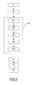
- the mounting method of the station 1 comprises a prefabrication step S1 in which each prefabricated support 10, 11 is made of concrete in the zone of 23.
- a transport step S2 of each prefabricated support 10, 11 is carried out, from the manufacturing zone 23, to the mounting zone 14.
- the prefabricated supports 10, 11 are transported. by truck, by helicopter, or any other motorized means powerful enough to lift and transport at least one prefabricated support 10, 11.
- a mounting step S3 of the station 1 comprising an installation S33 of each prefabricated support on a predetermined location of the ground delimiting the mounting zone 14.
- the mounting step S3 may comprise, before the pos S33 of the prefabricated supports, an earth-moving step S31 in which the pit 17 is dug into the ground of the mounting zone 14.
- the mounting step S3 may further comprise an S32 deposit of sand bed 20, or a realization of a concrete screed, with or without mortar, on the bottom of the pit 17.
- the first prefabricated support 10 is placed on the bottom of the second stage 19, via the sand bed 20, and the second prefabricated support 11 is placed on the bottom of the first stage 18, via the bed 20.
- the mounting step S3 may further comprise a fixing step S34 of the connecting element 33 between the two prefabricated supports 10, 11. Then, we each pylon 12 is mounted on the first and second prefabricated supports 10, 11, respectively.
- the mounting step S3 of the station 1 also comprises an assembly step S35 of the elements of the upper part 2, in which the frame 5 is assembled. , the pulley 6, the motor 8, and the drive shaft 9.
- the assembly of the elements S35 is carried out outside the mounting zone 14. Then the assembled structure is mounted on the pylons 12, 13.
- the roof 4 is mounted on the frame 5, then the cable 7 on the pulley 6.
- the dismantling method of the station 1, which has been mounted according to the mounting method described above, comprises a first step D1 in which the upper part 2 of the station 1 is removed. The cable 7 and the cable are removed beforehand. roof 4. Then, the assembled structure of the towers 12, 13 is removed and placed next to the mounting zone 14. Then the various elements of the structure are dismounted so that they can be reused, for example for subsequent assembly. of a new station, or for another use.
- the method may also comprise a dismantling step D2 of the lower part 3 of the station 1, in which the towers 12, 13 are removed from the prefabricated supports 10, 11.
- the dismounting method also comprises a third step D3 in which one transports each prefabricated support 10, 11 from the mounting zone 14 to a storage zone or to a new zone in which a new station can be mounted from the disassembled elements.
- a method of mounting a cable car station robust and less dependent on weather conditions.
- a station can be completely removable, to replace, in a new location, a station that can not be used on its original site, for example in case of avalanche risks that would not have been expected during the construction of the station.
Landscapes
- Engineering & Computer Science (AREA)
- Transportation (AREA)
- Mechanical Engineering (AREA)
- Conveying And Assembling Of Building Elements In Situ (AREA)
Claims (13)
- Verfahren zur Montage einer Seilbahnstation, insbesondere einer Sessel- oder Kabinenbahn, dadurch gekennzeichnet, dass es umfasst:- einen Vorfertigungsschritt (S1), bei dem mindestens eine vorgefertigte Betonstütze hergestellt wird, die dazu bestimmt ist, einen oberen Bereich der Station zu tragen, wobei der Vorfertigungsschritt in einem Produktionsbereich durchgeführt wird;- einen Transportschritt (S2) für jede vorgefertigte Stütze vom Produktionsbereich zu einem Montagebereich, der vom Produktionsbereich getrennt ist; und- einen Stations-Montageschritt (S3), umfassend ein Einsetzen (S33) jeder vorgefertigten Stütze an einer bestimmten Stelle des Bodens, der den Montagebereich begrenzt.
- Verfahren nach Anspruch 1, bei dem der Vorfertigungsschritt (S1) die Herstellung mindestens einer vorgefertigten Stütze aus mehreren getrennten Betonteilen, der Transportschritt (S2) den Transport der Teile jeder vorgefertigten Stütze vom Produktionsbereich zum Montagebereich und der Montageschritt (S3) das Einsetzen der Teile jeder vorgefertigten Stütze am vorbestimmten Ort des Bodens umfasst, der den Montagebereich begrenzt.
- Verfahren nach Anspruch 1 oder 2, bei dem der Montageschritt (S3) ein Einsetzen (S33) mindestens zweier vorgefertigter Stützen im Montagebereich und eine Befestigung (S34) mindestens eines Verbindungselements an beiden vorgefertigten Stützen umfasst, wobei jede vorgefertigte Stütze mit einem ersten Befestigungsmittel versehen ist, das mit einem zweiten Befestigungsmittel zusammenwirkt, das am Verbindungselement vorgesehen ist.
- Verfahren nach einem der Ansprüche 1 bis 3, bei dem jede vorgefertigte Stütze mindestens ein Hebeelement umfasst, das dazu bestimmt ist, die Stütze beim Transportschritt (S2) und während der Einbauphase (S33) der vorgefertigten Stützen anzuheben.
- Verfahren nach einem der Ansprüche 1 bis 4, bei dem der Montageschritt (S3) das Aufbringen (S32) eines Sandbettes auf dem vorbestimmten Bodenbereich umfasst, der den Einbaubereich begrenzt, um den Montagebereich zu bilden, und ein Aufsetzen (S33) jeder vorgefertigten Stütze auf dem aufgebrachten Sandbett.
- Verfahren nach einem der Ansprüche 1 bis 4, bei dem der Montageschritt (S3) die Herstellung mindestens eines Betonfundaments auf dem vorbestimmten Bodenbereich umfasst, der den Montagebereich begrenzt, um den Montagebereich zu bilden, und ein Aufsetzen (S33) jeder vorgefertigten Stütze auf dem entstandenen Betonfundament.
- Verfahren nach einem der Ansprüche 1 bis 4, bei dem der Montageschritt (S3) die Herstellung mindestens eines Betonfundaments auf dem vorbestimmten Bodenbereich umfasst, der den Montagebereich begrenzt, um den Montagebereich zu bilden, wobei das Betonfundament mindestens einen hervorstehenden Anschlag umfasst, und ein Aufsetzen (S33) jeder vorgefertigten Stütze auf dem entstandenen Betonfundament und anstoßend an den genannten Anschlag.
- Verfahren nach einem der Ansprüche 1 bis 4, bei dem der Montageschritt (S3) die Herstellung mindestens eines Betonfundaments auf dem vorbestimmten Bodenbereich umfasst, der den Montagebereich begrenzt, eine Herstellung mindestens einer Mörtelauflage auf dem Betonfundament, um den Montagebereich zu bilden, und ein Aufsetzen (S33) jeder vorgefertigten Stütze auf der entstandenen Mörtelauflage.
- Verfahren zur Demontage einer Seilbahnstation, insbesondere einer Sessel- oder Kabinenbahnstation, wobei die Station mindestens eine vorgefertigte Betonstütze umfasst, die dazu bestimmt ist, einen oberen Teil der Station zu tragen, wobei die Station auf einem Montagebereich nach einem der Ansprüche 1 bis 8 montiert ist, das umfasst:- eine Demontage (D1) des oberen Teils der Station; und- einen Transport (D3) jeder vorgefertigten Stütze vom Montagebereich zu einem Lagerbereich, der vom Montagebereich getrennt ist.
- Demontierbare Seilbahnstation, insbesondere einer Sessel- oder Kabinenbahnstation, die auf einem Montagebereich (14) montiert ist und mindestens eine vorgefertigte Betonstütze (10, 11) umfasst, die dazu bestimmt ist, einen oberen Teil (2) der Station zu tragen, welche vorgefertigte Stütze (10, 11) geeignet ist, von dem Montagebereich (14) zu einem Lagerbereich transportiert zu werden, der vom Montagebereich (14) getrennt ist.
- Station nach Anspruch 10, bei der mindestens eine vorgefertigte Stütze mehrere getrennte Betonteile umfasst, die geeignet sind, vom Montagebereich (14) zu dem vom Montagebereich (14) getrennten Lagerbereich transportiert zu werden.
- Station nach Anspruch 10 oder 11, die mindestens zwei vorgefertigte Stützen (10, 11) und mindestens ein Verbindungselement (33) umfasst, das an beiden vorgefertigten Stützen (10, 11) befestigt ist, wobei jede vorgefertigte Stütze (10, 11) mit einem ersten Befestigungsmittel (30) versehen ist, das mit einem zweiten Befestigungsmittel (34) zusammenwirkt, das an dem Verbindungselement (33) vorgesehen ist.
- Station nach einem der Ansprüche 10 bis 12, bei der jede vorgefertigte Stütze (10, 11) mindestens ein Hebeelement (29) umfasst, das dazu bestimmt ist, die vorgefertigte Stütze (10, 11) für ihren Transport anzuheben.
Applications Claiming Priority (1)
| Application Number | Priority Date | Filing Date | Title |
|---|---|---|---|
| FR1202497A FR2995579B1 (fr) | 2012-09-20 | 2012-09-20 | Station de telepherique, notamment de telesiege ou telecabine, et procedes de montage et de demontage d'une telle station |
Publications (2)
| Publication Number | Publication Date |
|---|---|
| EP2711260A1 EP2711260A1 (de) | 2014-03-26 |
| EP2711260B1 true EP2711260B1 (de) | 2015-07-22 |
Family
ID=47172718
Family Applications (1)
| Application Number | Title | Priority Date | Filing Date |
|---|---|---|---|
| EP13354034.4A Not-in-force EP2711260B1 (de) | 2012-09-20 | 2013-09-16 | Seilbahnstation, insbesondere eines Sesselliftes oder einer Gondelbahn, und Montage- und Demontageverfahren einer solchen Station |
Country Status (2)
| Country | Link |
|---|---|
| EP (1) | EP2711260B1 (de) |
| FR (1) | FR2995579B1 (de) |
Families Citing this family (2)
| Publication number | Priority date | Publication date | Assignee | Title |
|---|---|---|---|---|
| CN114753406A (zh) * | 2022-03-11 | 2022-07-15 | 中建八局轨道交通建设有限公司 | 用于安装半高安全门的站台板的加固结构及其施工方法 |
| WO2026020245A1 (en) * | 2024-07-23 | 2026-01-29 | Lodestar Structures Inc. | Modular transportation system |
Family Cites Families (2)
| Publication number | Priority date | Publication date | Assignee | Title |
|---|---|---|---|---|
| FR2255200B1 (de) * | 1973-12-20 | 1976-07-23 | Pomagalski Sa | |
| DE2548555B2 (de) * | 1975-10-30 | 1979-09-27 | Demag Ag, 4100 Duisburg | Hochbahnstation |
-
2012
- 2012-09-20 FR FR1202497A patent/FR2995579B1/fr not_active Expired - Fee Related
-
2013
- 2013-09-16 EP EP13354034.4A patent/EP2711260B1/de not_active Not-in-force
Also Published As
| Publication number | Publication date |
|---|---|
| FR2995579A1 (fr) | 2014-03-21 |
| EP2711260A1 (de) | 2014-03-26 |
| FR2995579B1 (fr) | 2014-10-17 |
Similar Documents
| Publication | Publication Date | Title |
|---|---|---|
| FR3029231A1 (de) | ||
| FR2823512A1 (fr) | Viaduc pour ligne ferroviaire ou autre | |
| EP0329517B1 (de) | Schrägkabelbrücke und Verfahren zu deren Bau | |
| EP3049580B1 (de) | Verfahren zur herstellung eines grundankers | |
| EP2837742B1 (de) | Verankerungsvorrichtung für Bauwerksfundamente von Seilbahnen, und Herstellungsverfahren einer solchen Vorrichtung | |
| EP0425364A1 (de) | Station für eine Eisenbahn oder andere Bahn auf einem Viadukt | |
| EP2711260A1 (de) | Seilbahnstation, insbesondere eines Sesselliftes oder einer Gondelbahn, und Montage- und Demontageverfahren einer solchen Station | |
| EP1660725B1 (de) | Metallbrücke und herstellungsverfahren dafür | |
| FR2964133A1 (fr) | Dispositif de maintien sur une plate forme d'un mat vertical | |
| FR2903437A1 (fr) | Element prefabrique pour la realisation d'une paroi en beton arme et paroi ainsi realisee | |
| EP2815036B1 (de) | Wasserdichtes mobiles gebäude bestehend aus mehreren abschnitten | |
| EP2231947B1 (de) | Vorgefertigtes element zur herstellung einer stahlbetonplatte und so hergestellte platte | |
| FR3065977B1 (fr) | Ensemble d’elements de structure destines a former un parking aerien a etages, et parking aerien a etages correspondant | |
| FR3019565A1 (fr) | Procede de realisation d'un carrefour de tramway | |
| FR2741896A1 (fr) | Perfectionnements aux procedes pour rehabiliter les ponts suspendus et aux ponts ainsi rehabilites | |
| EP0286764A1 (de) | Transportsystem für Fertighäuser, Fertighaus mit Vorrichtungen für sein Transport und Fertigungsverfahren für ein solches Haus | |
| FR2634236A1 (fr) | Procede pour reparer une fondation comportant des tetes de pieux deteriorees, notamment de pieux en bois | |
| FR2676478A1 (fr) | Procede pour la construction d'ouvrages tels que des ponts et ouvrages ainsi obtenus. | |
| FR3067372A1 (fr) | Dispositif d'amenagement d'une arete de bord de quai et le procede pour sa realisation | |
| BE507168A (de) | ||
| OA21697A (fr) | Plate-forme élévatrice pour la construction de tréteaux en béton à multiétages et procédé d'exécution. | |
| FR2612534A1 (fr) | Procede pour confectionner une structure en beton, telle qu'un tablier de pont, et appareillage pour sa mise en oeuvre | |
| BE1031956A1 (fr) | Dalle de tablier préfabriquée de pont à haubans et procédé de construction de celle-ci | |
| FR3031526A1 (fr) | Massif d'ancrage de pylone | |
| FR3126717A1 (fr) | Pièce de fondation pour des fondations ponctuelles notamment en limite de propriété et procédé de fabrication d’un plancher |
Legal Events
| Date | Code | Title | Description |
|---|---|---|---|
| PUAI | Public reference made under article 153(3) epc to a published international application that has entered the european phase |
Free format text: ORIGINAL CODE: 0009012 |
|
| AK | Designated contracting states |
Kind code of ref document: A1 Designated state(s): AL AT BE BG CH CY CZ DE DK EE ES FI FR GB GR HR HU IE IS IT LI LT LU LV MC MK MT NL NO PL PT RO RS SE SI SK SM TR |
|
| AX | Request for extension of the european patent |
Extension state: BA ME |
|
| 17P | Request for examination filed |
Effective date: 20140922 |
|
| RBV | Designated contracting states (corrected) |
Designated state(s): AL AT BE BG CH CY CZ DE DK EE ES FI FR GB GR HR HU IE IS IT LI LT LU LV MC MK MT NL NO PL PT RO RS SE SI SK SM TR |
|
| GRAP | Despatch of communication of intention to grant a patent |
Free format text: ORIGINAL CODE: EPIDOSNIGR1 |
|
| INTG | Intention to grant announced |
Effective date: 20150126 |
|
| RIN1 | Information on inventor provided before grant (corrected) |
Inventor name: LANIER, DAMIEN Inventor name: LAVILLE, PHILIPPE Inventor name: VIBERT, GILLES |
|
| GRAS | Grant fee paid |
Free format text: ORIGINAL CODE: EPIDOSNIGR3 |
|
| RAP1 | Party data changed (applicant data changed or rights of an application transferred) |
Owner name: POMA |
|
| GRAA | (expected) grant |
Free format text: ORIGINAL CODE: 0009210 |
|
| AK | Designated contracting states |
Kind code of ref document: B1 Designated state(s): AL AT BE BG CH CY CZ DE DK EE ES FI FR GB GR HR HU IE IS IT LI LT LU LV MC MK MT NL NO PL PT RO RS SE SI SK SM TR |
|
| REG | Reference to a national code |
Ref country code: GB Ref legal event code: FG4D Free format text: NOT ENGLISH |
|
| REG | Reference to a national code |
Ref country code: CH Ref legal event code: EP |
|
| REG | Reference to a national code |
Ref country code: IE Ref legal event code: FG4D Free format text: LANGUAGE OF EP DOCUMENT: FRENCH |
|
| REG | Reference to a national code |
Ref country code: AT Ref legal event code: REF Ref document number: 737704 Country of ref document: AT Kind code of ref document: T Effective date: 20150815 |
|
| REG | Reference to a national code |
Ref country code: DE Ref legal event code: R096 Ref document number: 602013002377 Country of ref document: DE |
|
| REG | Reference to a national code |
Ref country code: FR Ref legal event code: PLFP Year of fee payment: 3 |
|
| REG | Reference to a national code |
Ref country code: CH Ref legal event code: NV Representative=s name: CABINET ROLAND NITHARDT CONSEILS EN PROPRIETE , CH |
|
| REG | Reference to a national code |
Ref country code: LT Ref legal event code: MG4D |
|
| REG | Reference to a national code |
Ref country code: NL Ref legal event code: MP Effective date: 20150722 |
|
| PG25 | Lapsed in a contracting state [announced via postgrant information from national office to epo] |
Ref country code: FI Free format text: LAPSE BECAUSE OF FAILURE TO SUBMIT A TRANSLATION OF THE DESCRIPTION OR TO PAY THE FEE WITHIN THE PRESCRIBED TIME-LIMIT Effective date: 20150722 Ref country code: NO Free format text: LAPSE BECAUSE OF FAILURE TO SUBMIT A TRANSLATION OF THE DESCRIPTION OR TO PAY THE FEE WITHIN THE PRESCRIBED TIME-LIMIT Effective date: 20151022 Ref country code: LV Free format text: LAPSE BECAUSE OF FAILURE TO SUBMIT A TRANSLATION OF THE DESCRIPTION OR TO PAY THE FEE WITHIN THE PRESCRIBED TIME-LIMIT Effective date: 20150722 Ref country code: GR Free format text: LAPSE BECAUSE OF FAILURE TO SUBMIT A TRANSLATION OF THE DESCRIPTION OR TO PAY THE FEE WITHIN THE PRESCRIBED TIME-LIMIT Effective date: 20151023 Ref country code: LT Free format text: LAPSE BECAUSE OF FAILURE TO SUBMIT A TRANSLATION OF THE DESCRIPTION OR TO PAY THE FEE WITHIN THE PRESCRIBED TIME-LIMIT Effective date: 20150722 |
|
| PG25 | Lapsed in a contracting state [announced via postgrant information from national office to epo] |
Ref country code: RS Free format text: LAPSE BECAUSE OF FAILURE TO SUBMIT A TRANSLATION OF THE DESCRIPTION OR TO PAY THE FEE WITHIN THE PRESCRIBED TIME-LIMIT Effective date: 20150722 Ref country code: ES Free format text: LAPSE BECAUSE OF FAILURE TO SUBMIT A TRANSLATION OF THE DESCRIPTION OR TO PAY THE FEE WITHIN THE PRESCRIBED TIME-LIMIT Effective date: 20150722 Ref country code: HR Free format text: LAPSE BECAUSE OF FAILURE TO SUBMIT A TRANSLATION OF THE DESCRIPTION OR TO PAY THE FEE WITHIN THE PRESCRIBED TIME-LIMIT Effective date: 20150722 Ref country code: IS Free format text: LAPSE BECAUSE OF FAILURE TO SUBMIT A TRANSLATION OF THE DESCRIPTION OR TO PAY THE FEE WITHIN THE PRESCRIBED TIME-LIMIT Effective date: 20151122 Ref country code: PL Free format text: LAPSE BECAUSE OF FAILURE TO SUBMIT A TRANSLATION OF THE DESCRIPTION OR TO PAY THE FEE WITHIN THE PRESCRIBED TIME-LIMIT Effective date: 20150722 Ref country code: PT Free format text: LAPSE BECAUSE OF FAILURE TO SUBMIT A TRANSLATION OF THE DESCRIPTION OR TO PAY THE FEE WITHIN THE PRESCRIBED TIME-LIMIT Effective date: 20151123 Ref country code: SE Free format text: LAPSE BECAUSE OF FAILURE TO SUBMIT A TRANSLATION OF THE DESCRIPTION OR TO PAY THE FEE WITHIN THE PRESCRIBED TIME-LIMIT Effective date: 20150722 |
|
| REG | Reference to a national code |
Ref country code: DE Ref legal event code: R097 Ref document number: 602013002377 Country of ref document: DE |
|
| PG25 | Lapsed in a contracting state [announced via postgrant information from national office to epo] |
Ref country code: CZ Free format text: LAPSE BECAUSE OF FAILURE TO SUBMIT A TRANSLATION OF THE DESCRIPTION OR TO PAY THE FEE WITHIN THE PRESCRIBED TIME-LIMIT Effective date: 20150722 Ref country code: SK Free format text: LAPSE BECAUSE OF FAILURE TO SUBMIT A TRANSLATION OF THE DESCRIPTION OR TO PAY THE FEE WITHIN THE PRESCRIBED TIME-LIMIT Effective date: 20150722 Ref country code: LU Free format text: LAPSE BECAUSE OF FAILURE TO SUBMIT A TRANSLATION OF THE DESCRIPTION OR TO PAY THE FEE WITHIN THE PRESCRIBED TIME-LIMIT Effective date: 20150916 Ref country code: MC Free format text: LAPSE BECAUSE OF FAILURE TO SUBMIT A TRANSLATION OF THE DESCRIPTION OR TO PAY THE FEE WITHIN THE PRESCRIBED TIME-LIMIT Effective date: 20150722 Ref country code: DK Free format text: LAPSE BECAUSE OF FAILURE TO SUBMIT A TRANSLATION OF THE DESCRIPTION OR TO PAY THE FEE WITHIN THE PRESCRIBED TIME-LIMIT Effective date: 20150722 Ref country code: EE Free format text: LAPSE BECAUSE OF FAILURE TO SUBMIT A TRANSLATION OF THE DESCRIPTION OR TO PAY THE FEE WITHIN THE PRESCRIBED TIME-LIMIT Effective date: 20150722 |
|
| PLBE | No opposition filed within time limit |
Free format text: ORIGINAL CODE: 0009261 |
|
| STAA | Information on the status of an ep patent application or granted ep patent |
Free format text: STATUS: NO OPPOSITION FILED WITHIN TIME LIMIT |
|
| PG25 | Lapsed in a contracting state [announced via postgrant information from national office to epo] |
Ref country code: RO Free format text: LAPSE BECAUSE OF FAILURE TO SUBMIT A TRANSLATION OF THE DESCRIPTION OR TO PAY THE FEE WITHIN THE PRESCRIBED TIME-LIMIT Effective date: 20150722 |
|
| 26N | No opposition filed |
Effective date: 20160425 |
|
| REG | Reference to a national code |
Ref country code: IE Ref legal event code: MM4A |
|
| PG25 | Lapsed in a contracting state [announced via postgrant information from national office to epo] |
Ref country code: IE Free format text: LAPSE BECAUSE OF NON-PAYMENT OF DUE FEES Effective date: 20150916 |
|
| PG25 | Lapsed in a contracting state [announced via postgrant information from national office to epo] |
Ref country code: SI Free format text: LAPSE BECAUSE OF FAILURE TO SUBMIT A TRANSLATION OF THE DESCRIPTION OR TO PAY THE FEE WITHIN THE PRESCRIBED TIME-LIMIT Effective date: 20150722 |
|
| REG | Reference to a national code |
Ref country code: FR Ref legal event code: PLFP Year of fee payment: 4 |
|
| PG25 | Lapsed in a contracting state [announced via postgrant information from national office to epo] |
Ref country code: MT Free format text: LAPSE BECAUSE OF FAILURE TO SUBMIT A TRANSLATION OF THE DESCRIPTION OR TO PAY THE FEE WITHIN THE PRESCRIBED TIME-LIMIT Effective date: 20150722 |
|
| PG25 | Lapsed in a contracting state [announced via postgrant information from national office to epo] |
Ref country code: BG Free format text: LAPSE BECAUSE OF FAILURE TO SUBMIT A TRANSLATION OF THE DESCRIPTION OR TO PAY THE FEE WITHIN THE PRESCRIBED TIME-LIMIT Effective date: 20150722 Ref country code: HU Free format text: LAPSE BECAUSE OF FAILURE TO SUBMIT A TRANSLATION OF THE DESCRIPTION OR TO PAY THE FEE WITHIN THE PRESCRIBED TIME-LIMIT; INVALID AB INITIO Effective date: 20130916 |
|
| PG25 | Lapsed in a contracting state [announced via postgrant information from national office to epo] |
Ref country code: NL Free format text: LAPSE BECAUSE OF FAILURE TO SUBMIT A TRANSLATION OF THE DESCRIPTION OR TO PAY THE FEE WITHIN THE PRESCRIBED TIME-LIMIT Effective date: 20150722 Ref country code: CY Free format text: LAPSE BECAUSE OF FAILURE TO SUBMIT A TRANSLATION OF THE DESCRIPTION OR TO PAY THE FEE WITHIN THE PRESCRIBED TIME-LIMIT Effective date: 20150722 |
|
| REG | Reference to a national code |
Ref country code: AT Ref legal event code: UEP Ref document number: 737704 Country of ref document: AT Kind code of ref document: T Effective date: 20150722 |
|
| PG25 | Lapsed in a contracting state [announced via postgrant information from national office to epo] |
Ref country code: BE Free format text: LAPSE BECAUSE OF NON-PAYMENT OF DUE FEES Effective date: 20150930 |
|
| REG | Reference to a national code |
Ref country code: FR Ref legal event code: PLFP Year of fee payment: 5 |
|
| GBPC | Gb: european patent ceased through non-payment of renewal fee |
Effective date: 20170916 |
|
| PG25 | Lapsed in a contracting state [announced via postgrant information from national office to epo] |
Ref country code: SM Free format text: LAPSE BECAUSE OF FAILURE TO SUBMIT A TRANSLATION OF THE DESCRIPTION OR TO PAY THE FEE WITHIN THE PRESCRIBED TIME-LIMIT Effective date: 20150722 |
|
| PG25 | Lapsed in a contracting state [announced via postgrant information from national office to epo] |
Ref country code: MK Free format text: LAPSE BECAUSE OF FAILURE TO SUBMIT A TRANSLATION OF THE DESCRIPTION OR TO PAY THE FEE WITHIN THE PRESCRIBED TIME-LIMIT Effective date: 20150722 Ref country code: TR Free format text: LAPSE BECAUSE OF FAILURE TO SUBMIT A TRANSLATION OF THE DESCRIPTION OR TO PAY THE FEE WITHIN THE PRESCRIBED TIME-LIMIT Effective date: 20150722 |
|
| PG25 | Lapsed in a contracting state [announced via postgrant information from national office to epo] |
Ref country code: GB Free format text: LAPSE BECAUSE OF NON-PAYMENT OF DUE FEES Effective date: 20170916 |
|
| REG | Reference to a national code |
Ref country code: FR Ref legal event code: PLFP Year of fee payment: 6 |
|
| PG25 | Lapsed in a contracting state [announced via postgrant information from national office to epo] |
Ref country code: AL Free format text: LAPSE BECAUSE OF FAILURE TO SUBMIT A TRANSLATION OF THE DESCRIPTION OR TO PAY THE FEE WITHIN THE PRESCRIBED TIME-LIMIT Effective date: 20150722 |
|
| REG | Reference to a national code |
Ref country code: CH Ref legal event code: NV Representative=s name: ACTOSPHERE SARL, CH |
|
| PGFP | Annual fee paid to national office [announced via postgrant information from national office to epo] |
Ref country code: DE Payment date: 20200928 Year of fee payment: 8 Ref country code: FR Payment date: 20200928 Year of fee payment: 8 |
|
| PGFP | Annual fee paid to national office [announced via postgrant information from national office to epo] |
Ref country code: IT Payment date: 20200908 Year of fee payment: 8 Ref country code: CH Payment date: 20200929 Year of fee payment: 8 Ref country code: AT Payment date: 20200918 Year of fee payment: 8 |
|
| REG | Reference to a national code |
Ref country code: DE Ref legal event code: R119 Ref document number: 602013002377 Country of ref document: DE |
|
| REG | Reference to a national code |
Ref country code: CH Ref legal event code: PL |
|
| REG | Reference to a national code |
Ref country code: AT Ref legal event code: MM01 Ref document number: 737704 Country of ref document: AT Kind code of ref document: T Effective date: 20210916 |
|
| PG25 | Lapsed in a contracting state [announced via postgrant information from national office to epo] |
Ref country code: FR Free format text: LAPSE BECAUSE OF NON-PAYMENT OF DUE FEES Effective date: 20210930 Ref country code: DE Free format text: LAPSE BECAUSE OF NON-PAYMENT OF DUE FEES Effective date: 20220401 |
|
| PG25 | Lapsed in a contracting state [announced via postgrant information from national office to epo] |
Ref country code: LI Free format text: LAPSE BECAUSE OF NON-PAYMENT OF DUE FEES Effective date: 20210930 Ref country code: CH Free format text: LAPSE BECAUSE OF NON-PAYMENT OF DUE FEES Effective date: 20210930 Ref country code: AT Free format text: LAPSE BECAUSE OF NON-PAYMENT OF DUE FEES Effective date: 20210916 |
|
| PG25 | Lapsed in a contracting state [announced via postgrant information from national office to epo] |
Ref country code: IT Free format text: LAPSE BECAUSE OF NON-PAYMENT OF DUE FEES Effective date: 20210916 |