EP0286853B2 - Verfahren zur Abdichtung von Schuhen im Sohlenbereich - Google Patents
Verfahren zur Abdichtung von Schuhen im Sohlenbereich Download PDFInfo
- Publication number
- EP0286853B2 EP0286853B2 EP88104129A EP88104129A EP0286853B2 EP 0286853 B2 EP0286853 B2 EP 0286853B2 EP 88104129 A EP88104129 A EP 88104129A EP 88104129 A EP88104129 A EP 88104129A EP 0286853 B2 EP0286853 B2 EP 0286853B2
- Authority
- EP
- European Patent Office
- Prior art keywords
- layer
- insole
- region
- waterproof
- sealing lip
- Prior art date
- Legal status (The legal status is an assumption and is not a legal conclusion. Google has not performed a legal analysis and makes no representation as to the accuracy of the status listed.)
- Expired - Lifetime
Links
Images
Classifications
-
- A—HUMAN NECESSITIES
- A43—FOOTWEAR
- A43D—MACHINES, TOOLS, EQUIPMENT OR METHODS FOR MANUFACTURING OR REPAIRING FOOTWEAR
- A43D1/00—Foot or last measuring devices; Measuring devices for shoe parts
-
- B—PERFORMING OPERATIONS; TRANSPORTING
- B29—WORKING OF PLASTICS; WORKING OF SUBSTANCES IN A PLASTIC STATE IN GENERAL
- B29D—PRODUCING PARTICULAR ARTICLES FROM PLASTICS OR FROM SUBSTANCES IN A PLASTIC STATE
- B29D35/00—Producing footwear
- B29D35/06—Producing footwear having soles or heels formed and joined on to preformed uppers using a moulding technique, e.g. by injection moulding, pressing and vulcanising
- B29D35/061—Producing footwear having soles or heels formed and joined on to preformed uppers using a moulding technique, e.g. by injection moulding, pressing and vulcanising by injection moulding
-
- A—HUMAN NECESSITIES
- A43—FOOTWEAR
- A43B—CHARACTERISTIC FEATURES OF FOOTWEAR; PARTS OF FOOTWEAR
- A43B17/00—Insoles for insertion, e.g. footbeds or inlays, for attachment to the shoe after the upper has been joined
- A43B17/10—Insoles for insertion, e.g. footbeds or inlays, for attachment to the shoe after the upper has been joined specially adapted for sweaty feet; waterproof
- A43B17/107—Insoles for insertion, e.g. footbeds or inlays, for attachment to the shoe after the upper has been joined specially adapted for sweaty feet; waterproof waterproof
-
- A—HUMAN NECESSITIES
- A43—FOOTWEAR
- A43B—CHARACTERISTIC FEATURES OF FOOTWEAR; PARTS OF FOOTWEAR
- A43B7/00—Footwear with health or hygienic arrangements
- A43B7/12—Special watertight footwear
- A43B7/125—Special watertight footwear provided with a vapour permeable member, e.g. a membrane
Definitions
- the invention relates to a method for waterproofing the connection zone between a waterproof shoe upper with a lasting fold and an insole area the shoe by means of a layer of waterproof material, which are sprayed onto the connection zone using an injection mold becomes.
- Shoes have been manufactured in recent times, their shoelaces made of waterproof and preferably vapor permeable material. There are difficulties a waterproof connection between the upper and the outsole to be attached to it.
- the upper is attached glued to the insole using a sticking process and a sole is applied to this glued unit, the can be a midsole or directly the outsole.
- the weak point in this solution is the glue points between Insole and upper, since the glue is either from the outset not the entire transition area between The upper and insole seal or are exposed to stress brittle and therefore permeable to water when using shoes can be.
- GB-A-1 228 172 shows a method for molding outsoles made of liquefiable material, which with the help of an injection mold on the connecting zone between an upper and the upper Insole area of the shoe is sprayed on.
- an injection mold On the bottom the upper part connected to the insole becomes a one-piece Injection mold attached, one to the side of the shaft side wall protruding sealing lip arrangement which has the top the molded outsole overlaps. So this one-piece
- the injection mold is still removable from the molded outsole, it consists of an elastic material.
- the invention is based on the object to make available a method by means of which Usage of any outsoles also one long usage time reliable waterproof connection guaranteed between the upper and insole becomes.
- a relatively simple injection mold can be used.
- a spray stamp with an upright is sufficient Sealing lip is provided, the course of which in corresponds approximately to the contour of the insole. Because it to the exact attachment line of the sealing lip on the not with the insole provided arrives, this form can be used for a large number different sized shoes used will.
- the contour of the sealing lip preferably runs from the outer edge of the upper to the inside transferred.
- Any outsole can then be applied to the layer will.
- the sprayed layer needs then no longer to be visible, so the aesthetic Appearance of the shoe by such Layer does not need to be affected.
- the layer preferably consists of polyurethane, liquefied for spraying and with sprayed a pressure of preferably 3 to 5 at becomes. This pressure ensures that the liquid material in the area to be sealed between the insole and the upper and makes this connection waterproof.
- the upper of the shoe waterproof is at least a part, preferably the whole Upper made of waterproof material, which is preferably breathable.
- waterproof material which is preferably breathable.
- a film made from stretched Polytetrafluoroethylene (PTFE), a polyester membrane or a microporous polyurethane coating for example, PTFE, a polyester membrane or a microporous polyurethane coating.
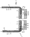
- Fig. 1 shows a shoe upper 1, which means a lasting adhesive 3 glued to an insole 4 is.
- the upper 1 can be made of different materials Materials exist.
- Fig. 1 there are two Possibilities presented.
- the left side shows one Upper made of a laminate 7 with an outer layer 9, a middle layer 11 a water-impermeable, vapor-permeable Membrane and an inner layer 13 is made.
- Fig. 1 shows an embodiment an upper with an outer layer 17, for example made of leather, which lined with a laminate that serves as lining which is in turn a waterproof, contains vapor permeable membrane.
- the lasting wedge 19 has a loose end region 21 who is not using the insole 4 is glued.
- the lining 15 is preferably in the lasting fold made shorter than the laminate 7 and only the area of the laminate provided with lining 15 7 glued to the insole 4. The over the area of the laminate 7 protruding from the lining forms the loose part of the lasting fold 19.
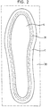
- Fig. 1 also schematically shows one of an injection molded sealing layer for clarification withdrawn injection mold 30 with one in itself closed sealing lip 31, which is roughly the shape the insole 4 follows, as can be seen in FIG. 2 is.
- the sealing lip parts lie during the spraying process 31l, 31r below the areas of Lasting glue 3 on the lasting folds 19.
- the injection mold 30 has an inflow opening provided, the outlet mouth in the area between the two sealing lip parts 31l and 31r lies.
- the sealing material 5 is liquefied for injection and with a pressure in the range of, for example 3 to 5 at (corresponds to approx.2.95 bar to 4.91 bar) in the enclosed by the sealing lip 31 Injected space. It penetrates liquid sealing material also in the area between the insole 4 and the loose ends 21 of the lasting fold 19. By the spraying process the entire space between the insole and inner contour lying between the sealing lip 31 the injection mold filled with the sealing material. After the sealing material has hardened is a waterproof seal in the floor area the upper connected to the insole 4 1 given.
Landscapes
- Engineering & Computer Science (AREA)
- Mechanical Engineering (AREA)
- Health & Medical Sciences (AREA)
- Epidemiology (AREA)
- General Health & Medical Sciences (AREA)
- Public Health (AREA)
- Footwear And Its Accessory, Manufacturing Method And Apparatuses (AREA)
- Crushing And Grinding (AREA)
- Holders For Apparel And Elements Relating To Apparel (AREA)
Description
- Fig. 1
- eine schematische Vertikalschnittansicht eines mit einer Brandsohle verklebten Schuhschaftes mit daran angesetzter Spritzform und der damit erzeugten Dichtungsschicht wobei die Spritzform nach dem Spritzprozeß bereits von der Dichtungsschicht weggezogen ist; und
- Fig. 2
- eine schematische Darstellung eines mit einer Brandsohle verklebten Schuhschaftes und einer daran angesetzten Spritzform.
Claims (8)
- Verfahren zur wasserundurchlässigen Abdichtung der Verbindungszone zwischen einem wasserdichten Schuhschaft mit Zwickeinschlag und einem Brandsohlenbereich des Schuhs mittels einer Schicht (5) aus verflüssigbarem, im abgehärteten Zustand wasserdichten Material, die mit Hilfe einer Spritzform auf die Verbindungszone aufgespritzt wird,(a) wobei an die Unterseite des mit dem Brandsohlenbereich (4) verbundenen Schuhschaftes (1) eine Spritzform (30) angesetzt wird, die eine zum Brandsohlenbereich (4) hochstehende Dichlippenanordnung '(31) aufweist, die entlang der abzudichtenden Verbindungszone verläuft;(b) wobei die Kontur der Dichtlippenanordnung (31) im wesentlichen der Kontur der Brandsohle entspricht;(c) wobei der Zwickeinschlag des Schaftes einen losen Endbereich (21) aufweist, der nicht mit der Brandsohle (4) verklebt ist, so daß beim Aufspritzen der Schicht (5) die Spritzmasse der Schicht (5) in dem von der Dichtlippenanordnung (31) begrenzten Bereich zwischen den Zwickeinschlag des Schaftes und die Brandsohle dringen kann; und(d) wobei auf die aufgespritzte Schicht (5) eine Laufsohle aufgebracht wird.
- Verfahren nach Anspruch 1,
dadurch gekennzeichnet,
daß die Schicht aus Polyurethan besteht. - Verfahren nach Anspruch 1,
dadurch gekennzeichnet,
daß die Schicht aus Polyvinylchlorid besteht. - Verfahren nach Anspruch 1,
dadurch gekennzeichnet,
daß die Schicht aus Naturkautschuk besteht. - Verfahren nach Anspruch 1,
dadurch gekennzeichnet,
daß die Schicht aus Synthese-Kautschuk besteht. - Verfahren nach einem der Ansprüche 1 bis 5,
dadurch gekennzeichnet,
daß mindestens ein Teil des Schuhschaftes (1) aus wasserdichtem, dampfdurchlässigem Material (11) besteht oder mit solchem Material ausgekleidet ist. - Verfahren nach Anspruch 6,
dadurch gekennzeichnet,
daß das wasserdichte, dampfdurchlässige Material eine Folie aus gerecktem Polytetrafluoräthylen, eine Polyestermembran oder eine mikroporöse Polyurethan-Beschichtung ist. - Verfahren nach einem der Ansprüche 1 bis 7 zur Abdichtung eines Zwickeinschlages (19) bei klebegezwickten Schuhen,
dadurch gekennzeichnet,
daß der innere Randbereich (21) des Zwickeinschlages (19) unverklebt gehalten wird,
daß der unverklebte Randbereich (21) innerhalb des von der Dichtlippenanordnung (31) begrenzten Bereichs positioniert wird
und daß das Material der Schicht auf beiden Seiten des losen Randbereichs (21) aufgebracht wird.
Priority Applications (1)
| Application Number | Priority Date | Filing Date | Title |
|---|---|---|---|
| AT88104129T ATE95676T1 (de) | 1987-04-15 | 1988-03-15 | Verfahren zur abdichtung von schuhen im sohlenbereich. |
Applications Claiming Priority (2)
| Application Number | Priority Date | Filing Date | Title |
|---|---|---|---|
| DE3712901 | 1987-04-15 | ||
| DE3712901A DE3712901C1 (de) | 1987-04-15 | 1987-04-15 | Verfahren zur Abdichtung von Schuhen im Sohlenbereich |
Publications (4)
| Publication Number | Publication Date |
|---|---|
| EP0286853A2 EP0286853A2 (de) | 1988-10-19 |
| EP0286853A3 EP0286853A3 (en) | 1990-10-10 |
| EP0286853B1 EP0286853B1 (de) | 1993-10-13 |
| EP0286853B2 true EP0286853B2 (de) | 1998-07-15 |
Family
ID=6325749
Family Applications (1)
| Application Number | Title | Priority Date | Filing Date |
|---|---|---|---|
| EP88104129A Expired - Lifetime EP0286853B2 (de) | 1987-04-15 | 1988-03-15 | Verfahren zur Abdichtung von Schuhen im Sohlenbereich |
Country Status (13)
| Country | Link |
|---|---|
| EP (1) | EP0286853B2 (de) |
| JP (1) | JPH062081B2 (de) |
| KR (1) | KR880012184A (de) |
| CN (1) | CN88102190A (de) |
| AT (1) | ATE95676T1 (de) |
| CA (1) | CA1333318C (de) |
| DD (1) | DD284590A5 (de) |
| DE (2) | DE3712901C1 (de) |
| HU (1) | HUT57564A (de) |
| PT (1) | PT87217B (de) |
| RO (1) | RO100073B1 (de) |
| TR (1) | TR25076A (de) |
| YU (1) | YU64088A (de) |
Families Citing this family (19)
| Publication number | Priority date | Publication date | Assignee | Title |
|---|---|---|---|---|
| DE3840087A1 (de) * | 1988-11-28 | 1990-05-31 | Wagner Lowa Schuhfab | Schuh - stichwort: kunststoffzwickrand |
| DE4000156C2 (de) * | 1990-01-04 | 1998-07-30 | Gore W L & Ass Gmbh | Verfahren zur Herstellung eines wasserdichten Schuhs sowie wasserdichter Schuh |
| WO1993000837A1 (en) * | 1991-07-12 | 1993-01-21 | W.L. Gore & Associates, Inc. | Waterproof footwear |
| DE4138836C5 (de) * | 1991-11-26 | 2004-07-15 | W.L. Gore & Associates Gmbh | Wasserdichtes, atmungsaktives Schuhwerk |
| DE4311768A1 (de) * | 1993-04-08 | 1994-10-13 | Gore W L & Ass Gmbh | Verfahren zur Abdichtung von Schuhen im Sohlenbereich |
| DE4429158C2 (de) * | 1994-07-30 | 1998-12-03 | Oskar Welz | Schuhwerk |
| DE4436495A1 (de) * | 1994-10-12 | 1996-04-18 | Gore W L & Ass Gmbh | Verfahren zur Abdichtung von Schuhen im Sohlenbereich |
| DE19738744A1 (de) * | 1997-09-04 | 1999-04-08 | Gore W L & Ass Gmbh | Schuh und Verfahren zu dessen Herstellung |
| WO2000024282A1 (de) * | 1998-10-28 | 2000-05-04 | W.L. Gore & Associates Gmbh | Schuhwerk mit abgedichtetem sohlenaufbau und verfahren zu dessen herstellung |
| AU1156500A (en) * | 1998-10-28 | 2000-05-15 | W.L. Gore & Associates Gmbh | Footwear having a lasting fold sealing and a method for the production thereof |
| ES2216574T3 (es) * | 1998-10-28 | 2004-10-16 | W.L. GORE & ASSOCIATES GMBH | Zapato impermeabilizado y procedimiento para su fabricacion. |
| US20020053148A1 (en) * | 1998-11-17 | 2002-05-09 | Franz Haimerl | Footwear with last area sealing and method for its production |
| WO2000044252A1 (de) * | 1999-01-29 | 2000-08-03 | W.L. Gore & Associates Gmbh | Schuhwerk mit abgedichteter funktionsschicht und verfahren zu dessen herstellung |
| AU6642100A (en) * | 1999-08-16 | 2001-03-13 | Gore Enterprise Holdings, Inc. | Waterproof breathable footwear with cemented outsoles |
| DE10020738C1 (de) * | 2000-04-27 | 2002-01-24 | Gore W L & Ass Gmbh | Schuhwerk mit abgedichtetem Zwickeinschlag und Verfahren zu dessen Herstellung |
| FR2826554B1 (fr) * | 2001-06-29 | 2004-01-16 | Salomon Sa | Chaussure |
| ITTV20030043A1 (it) * | 2003-03-11 | 2004-09-12 | Jolly Scarpe Spa | Procedimento per l'ottenimento di una calzatura impermeabile e traspirante e calzatura cosi' ottenuta. |
| CN102342622B (zh) * | 2010-07-29 | 2015-07-15 | 阿基里斯株式会社 | 防水鞋和其所采用的防水内衬 |
| CN107348617A (zh) * | 2017-08-31 | 2017-11-17 | 成都卡美奇鞋业有限公司 | 提高鞋底粘合强度的粘接制鞋工艺 |
Family Cites Families (5)
| Publication number | Priority date | Publication date | Assignee | Title |
|---|---|---|---|---|
| DE1680553A1 (de) * | 1967-06-16 | 1971-04-29 | Ashtabula Bow Socket Co | Fahrradgabelschaftrohr |
| GB1228172A (de) * | 1967-06-21 | 1971-04-15 | ||
| US4599810A (en) * | 1981-08-06 | 1986-07-15 | W. L. Gore & Associates | Waterproof shoe construction |
| DE3147202A1 (de) * | 1981-11-27 | 1983-06-01 | W.L.Gore & Co. GmbH, 8011 Putzbrunn | Wasserdampfdurchlaessiges (schweissdurchlaessiges) schuhwerk |
| FR2550065B1 (fr) * | 1983-08-01 | 1986-02-07 | Eymery Jean Pierre | Procede pour la fabrication d'articles chaussants a semelles minces en matiere plastique directement injectee sur tige |
-
1987
- 1987-04-15 DE DE3712901A patent/DE3712901C1/de not_active Expired
-
1988
- 1988-03-15 DE DE88104129T patent/DE3884843D1/de not_active Expired - Lifetime
- 1988-03-15 EP EP88104129A patent/EP0286853B2/de not_active Expired - Lifetime
- 1988-03-15 AT AT88104129T patent/ATE95676T1/de not_active IP Right Cessation
- 1988-03-30 YU YU00640/88A patent/YU64088A/xx unknown
- 1988-04-07 RO RO13296988A patent/RO100073B1/ro unknown
- 1988-04-12 PT PT87217A patent/PT87217B/pt not_active IP Right Cessation
- 1988-04-12 DD DD88314664A patent/DD284590A5/de not_active IP Right Cessation
- 1988-04-13 HU HU881904A patent/HUT57564A/hu unknown
- 1988-04-14 KR KR1019880004266A patent/KR880012184A/ko not_active Withdrawn
- 1988-04-14 CA CA000564088A patent/CA1333318C/en not_active Expired - Fee Related
- 1988-04-14 JP JP63090436A patent/JPH062081B2/ja not_active Expired - Lifetime
- 1988-04-15 CN CN198888102190A patent/CN88102190A/zh active Pending
- 1988-04-15 TR TR88/0280A patent/TR25076A/xx unknown
Also Published As
| Publication number | Publication date |
|---|---|
| ATE95676T1 (de) | 1993-10-15 |
| DE3884843D1 (de) | 1993-11-18 |
| DE3712901C1 (de) | 1988-08-04 |
| PT87217A (pt) | 1989-05-12 |
| KR880012184A (ko) | 1988-11-26 |
| RO100073B1 (en) | 1992-06-01 |
| EP0286853B1 (de) | 1993-10-13 |
| YU64088A (en) | 1990-06-30 |
| EP0286853A2 (de) | 1988-10-19 |
| TR25076A (tr) | 1992-09-23 |
| CN88102190A (zh) | 1988-11-02 |
| CA1333318C (en) | 1994-12-06 |
| EP0286853A3 (en) | 1990-10-10 |
| JPH062081B2 (ja) | 1994-01-12 |
| HUT57564A (en) | 1991-12-30 |
| DD284590A5 (de) | 1990-11-21 |
| JPS6420803A (en) | 1989-01-24 |
| PT87217B (pt) | 1994-09-30 |
Similar Documents
| Publication | Publication Date | Title |
|---|---|---|
| EP0286853B2 (de) | Verfahren zur Abdichtung von Schuhen im Sohlenbereich | |
| EP0785735B1 (de) | Verfahren zur abdichtung von schuhen im sohlenbereich | |
| DE60308750T2 (de) | Schuh mit wasserdurchlässigem und atmungsaktivem Oberschuh, der zumindest teilweise eine atmungsaktiv-gewordene wasserundurchlässige Sohle bedeckt | |
| EP0298360B1 (de) | Wasserdichtes Schuhwerk | |
| DE69221874T2 (de) | Herstellungsverfahren einer wasserdichten Schuhwaren | |
| DE7932339U1 (de) | Fußbekleidung | |
| DE1922667A1 (de) | Verfahren zur Herstellung von Schuhen | |
| DE2220983A1 (de) | Verfahren und vorrichtung zur herstellung von schuhen | |
| DE2702271A1 (de) | Skistiefel mit einer abdichtungseinrichtung zwischen einer aeusseren schale und einem inneren, eine einlage bildenden element | |
| DE4021538A1 (de) | Wasserdichter schuh | |
| EP0091536B1 (de) | Schuh und Spritzform zur Herstellung der Sohle desselben | |
| DE4311768A1 (de) | Verfahren zur Abdichtung von Schuhen im Sohlenbereich | |
| DE60128074T2 (de) | Verfahren zum Herstellen eines Schuhs | |
| AT396545B (de) | Verfahren zum herstellen von schuhwerk | |
| DE4004674A1 (de) | Wasserdichtes aber wasserdampfdurchlaessiges schuhwerk und verfahren zu dessen herstellung | |
| DE19547276A1 (de) | Wasserdichter Schuh und Verfahren zu dessen Herstellung | |
| DE1485628B1 (de) | Verfahren zum Herstellen eines Schuhes mit einem mehrschichtigen Boden | |
| DE8814974U1 (de) | Wasserundurchlässiger Schuh | |
| DE3043725A1 (de) | Flexible-schuh sowie verfahren zu seiner herstellung | |
| DE828073C (de) | Verfahren zum Herstellen von Schuhen | |
| AT229188B (de) | Verfahren zum Herstellen von Schuhen | |
| DE1485628C (de) | Verfahren zum Herstellen eines Schuhes mit einem mehrschichtigen Boden | |
| DE29601600U1 (de) | Wasserdichter Schuh | |
| EP0020330A1 (de) | Verfahren zur maschinellen herstellung von schuhwerk mit vollständig überzogenem schuhboden | |
| DE69725697T2 (de) | Verfahren zur Herstellung eines Schuhes |
Legal Events
| Date | Code | Title | Description |
|---|---|---|---|
| PUAI | Public reference made under article 153(3) epc to a published international application that has entered the european phase |
Free format text: ORIGINAL CODE: 0009012 |
|
| AK | Designated contracting states |
Kind code of ref document: A2 Designated state(s): AT BE CH DE ES FR GB GR IT LI LU NL SE |
|
| RAP1 | Party data changed (applicant data changed or rights of an application transferred) |
Owner name: W.L. GORE & ASSOCIATES GMBH |
|
| RAP1 | Party data changed (applicant data changed or rights of an application transferred) |
Owner name: W.L. GORE & ASSOCIATES GMBH |
|
| PUAL | Search report despatched |
Free format text: ORIGINAL CODE: 0009013 |
|
| AK | Designated contracting states |
Kind code of ref document: A3 Designated state(s): AT BE CH DE ES FR GB GR IT LI LU NL SE |
|
| 17P | Request for examination filed |
Effective date: 19901210 |
|
| 17Q | First examination report despatched |
Effective date: 19920130 |
|
| GRAA | (expected) grant |
Free format text: ORIGINAL CODE: 0009210 |
|
| AK | Designated contracting states |
Kind code of ref document: B1 Designated state(s): AT BE CH DE ES FR GB GR IT LI LU NL SE |
|
| PG25 | Lapsed in a contracting state [announced via postgrant information from national office to epo] |
Ref country code: SE Effective date: 19931013 Ref country code: NL Effective date: 19931013 Ref country code: GR Free format text: LAPSE BECAUSE OF FAILURE TO SUBMIT A TRANSLATION OF THE DESCRIPTION OR TO PAY THE FEE WITHIN THE PRESCRIBED TIME-LIMIT Effective date: 19931013 Ref country code: ES Free format text: THE PATENT HAS BEEN ANNULLED BY A DECISION OF A NATIONAL AUTHORITY Effective date: 19931013 Ref country code: BE Effective date: 19931013 |
|
| REF | Corresponds to: |
Ref document number: 95676 Country of ref document: AT Date of ref document: 19931015 Kind code of ref document: T |
|
| ITF | It: translation for a ep patent filed | ||
| REF | Corresponds to: |
Ref document number: 3884843 Country of ref document: DE Date of ref document: 19931118 |
|
| GBT | Gb: translation of ep patent filed (gb section 77(6)(a)/1977) |
Effective date: 19931108 |
|
| ET | Fr: translation filed | ||
| NLV1 | Nl: lapsed or annulled due to failure to fulfill the requirements of art. 29p and 29m of the patents act | ||
| PG25 | Lapsed in a contracting state [announced via postgrant information from national office to epo] |
Ref country code: LU Free format text: LAPSE BECAUSE OF NON-PAYMENT OF DUE FEES Effective date: 19940331 |
|
| PLBI | Opposition filed |
Free format text: ORIGINAL CODE: 0009260 |
|
| 26 | Opposition filed |
Opponent name: AKZO NOBEL FASER AG Effective date: 19940712 |
|
| PLAW | Interlocutory decision in opposition |
Free format text: ORIGINAL CODE: EPIDOS IDOP |
|
| PLAW | Interlocutory decision in opposition |
Free format text: ORIGINAL CODE: EPIDOS IDOP |
|
| PUAH | Patent maintained in amended form |
Free format text: ORIGINAL CODE: 0009272 |
|
| STAA | Information on the status of an ep patent application or granted ep patent |
Free format text: STATUS: PATENT MAINTAINED AS AMENDED |
|
| 27A | Patent maintained in amended form |
Effective date: 19980715 |
|
| AK | Designated contracting states |
Kind code of ref document: B2 Designated state(s): AT BE CH DE ES FR GB GR IT LI LU NL SE |
|
| REG | Reference to a national code |
Ref country code: CH Ref legal event code: AEN Free format text: AUFRECHTERHALTUNG DES PATENTES IN GEAENDERTER FORM |
|
| GBTA | Gb: translation of amended ep patent filed (gb section 77(6)(b)/1977) | ||
| ET3 | Fr: translation filed ** decision concerning opposition | ||
| PGFP | Annual fee paid to national office [announced via postgrant information from national office to epo] |
Ref country code: FR Payment date: 19990218 Year of fee payment: 12 |
|
| PGFP | Annual fee paid to national office [announced via postgrant information from national office to epo] |
Ref country code: CH Payment date: 19990224 Year of fee payment: 12 |
|
| PG25 | Lapsed in a contracting state [announced via postgrant information from national office to epo] |
Ref country code: LI Free format text: LAPSE BECAUSE OF NON-PAYMENT OF DUE FEES Effective date: 20000331 Ref country code: CH Free format text: LAPSE BECAUSE OF NON-PAYMENT OF DUE FEES Effective date: 20000331 |
|
| REG | Reference to a national code |
Ref country code: CH Ref legal event code: PL |
|
| PG25 | Lapsed in a contracting state [announced via postgrant information from national office to epo] |
Ref country code: FR Free format text: LAPSE BECAUSE OF NON-PAYMENT OF DUE FEES Effective date: 20001130 |
|
| REG | Reference to a national code |
Ref country code: FR Ref legal event code: ST |
|
| PGFP | Annual fee paid to national office [announced via postgrant information from national office to epo] |
Ref country code: GB Payment date: 20010221 Year of fee payment: 14 |
|
| REG | Reference to a national code |
Ref country code: GB Ref legal event code: IF02 |
|
| PG25 | Lapsed in a contracting state [announced via postgrant information from national office to epo] |
Ref country code: GB Free format text: LAPSE BECAUSE OF NON-PAYMENT OF DUE FEES Effective date: 20020315 |
|
| GBPC | Gb: european patent ceased through non-payment of renewal fee |
Effective date: 20020315 |
|
| PG25 | Lapsed in a contracting state [announced via postgrant information from national office to epo] |
Ref country code: IT Free format text: LAPSE BECAUSE OF NON-PAYMENT OF DUE FEES;WARNING: LAPSES OF ITALIAN PATENTS WITH EFFECTIVE DATE BEFORE 2007 MAY HAVE OCCURRED AT ANY TIME BEFORE 2007. THE CORRECT EFFECTIVE DATE MAY BE DIFFERENT FROM THE ONE RECORDED. Effective date: 20050315 |
|
| PGFP | Annual fee paid to national office [announced via postgrant information from national office to epo] |
Ref country code: AT Payment date: 20060221 Year of fee payment: 19 |
|
| PGFP | Annual fee paid to national office [announced via postgrant information from national office to epo] |
Ref country code: DE Payment date: 20070430 Year of fee payment: 20 |
|
| PG25 | Lapsed in a contracting state [announced via postgrant information from national office to epo] |
Ref country code: AT Free format text: LAPSE BECAUSE OF NON-PAYMENT OF DUE FEES Effective date: 20070315 |