EP0286890A2 - Ecran pour armature à lampe fluorescente - Google Patents
Ecran pour armature à lampe fluorescente Download PDFInfo
- Publication number
- EP0286890A2 EP0286890A2 EP88104820A EP88104820A EP0286890A2 EP 0286890 A2 EP0286890 A2 EP 0286890A2 EP 88104820 A EP88104820 A EP 88104820A EP 88104820 A EP88104820 A EP 88104820A EP 0286890 A2 EP0286890 A2 EP 0286890A2
- Authority
- EP
- European Patent Office
- Prior art keywords
- transverse
- longitudinal
- lamella
- groove
- sections
- Prior art date
- Legal status (The legal status is an assumption and is not a legal conclusion. Google has not performed a legal analysis and makes no representation as to the accuracy of the status listed.)
- Granted
Links
Images


Classifications
-
- F—MECHANICAL ENGINEERING; LIGHTING; HEATING; WEAPONS; BLASTING
- F21—LIGHTING
- F21V—FUNCTIONAL FEATURES OR DETAILS OF LIGHTING DEVICES OR SYSTEMS THEREOF; STRUCTURAL COMBINATIONS OF LIGHTING DEVICES WITH OTHER ARTICLES, NOT OTHERWISE PROVIDED FOR
- F21V11/00—Screens not covered by groups F21V1/00, F21V3/00, F21V7/00 or F21V9/00
- F21V11/02—Screens not covered by groups F21V1/00, F21V3/00, F21V7/00 or F21V9/00 using parallel laminae or strips, e.g. of Venetian-blind type
-
- F—MECHANICAL ENGINEERING; LIGHTING; HEATING; WEAPONS; BLASTING
- F21—LIGHTING
- F21Y—INDEXING SCHEME ASSOCIATED WITH SUBCLASSES F21K, F21L, F21S and F21V, RELATING TO THE FORM OR THE KIND OF THE LIGHT SOURCES OR OF THE COLOUR OF THE LIGHT EMITTED
- F21Y2103/00—Elongate light sources, e.g. fluorescent tubes
Definitions
- the invention relates to a grid for fluorescent lamp lights with longitudinal slats and transverse slats arranged at right angles thereto according to the preamble of claim 1.
- Grids of this type are known from AT-PS 379 228 and DE-GM 85 08 740 also shows a similar construction.
- the lamellas of this grid have smooth reflecting surfaces over their height and the embossed groove provided at the front end of the transverse lamella positively takes on the edge of the cutout of the longitudinal lamella, on the one hand making the grid as a whole more stable and on the other hand preventing these "seams" from being prevented a gap is formed through which the light emitted by the lamp can fall.
- the longitudinal and transverse lamellas of such grids are made of thin aluminum sheets and the grid as a whole is a very unstable component, in which internal stresses result from mechanical stress as well as thermal expansion, which lead to, even if only small, deformations that the formation of gaps at the "seams" mentioned cannot be ruled out unless appropriate countermeasures are taken. Through such gaps, the light emitted by the lamp can fall outside. This can lead to effects that the viewer finds annoying.
- precautions have been successfully taken with the known constructions mentioned above, but the slats used for these grids are those which have a smooth reflecting surface over their entire height.
- the invention now proposes that those measures be taken with a grid of the type mentioned at the beginning of the characterizing part of claim 1. Despite the surfaces of the slats designed in this way the edge of the incision of the longitudinal lamella can be accommodated in such a way that a gap is avoided and so no light falls outwards in an uncontrolled manner.
- FIG. 1 shows a grid seen from below
- Fig. 2 shows the grid of Figure 1, seen obliquely from below
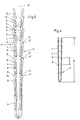
- Figure 3 shows the front end of a transverse lamella in view
- 4 shows a cross section along the line IV - IV in Fig. 3.
- 5 shows the end of a transverse lamella according to FIG. 3, but on an enlarged scale compared to this figure and in an oblique view
- Fig. 6 shows a longitudinal section through the groove at the front end of the transverse lamella and on a significantly enlarged scale compared to Fig. 3.
- FIG. 1 and 2 illustrate a simple grid for a single-lamp fluorescent lamp, with FIG. 1 showing a partial bottom view.
- This grid consists of two mutually parallel and spaced apart longitudinal slats 1. These two longitudinal slats 1 are now connected to one another by a plurality of mutually parallel and also spaced apart transverse slats 2.
- the fluorescent lamp 3 is located above these transverse lamellae 2 and in the center thereof.
- the longitudinal and transverse lamellae 1 and 2 are formed from thin metal sheets and have a refined, preferably mirrored surface.
- the cross-sectional shape of the longitudinal lamella 1 can be seen directly from FIG. 2; the cross-sectional shape of the transverse lamella is shown in Fig. 4, from which it can be seen that this transverse lamella is formed from a sheet metal strip bent essentially in a U-shape.
- this transverse lamella 2 has no smooth surface over height, rather its surface is divided by prismatic or wedge-shaped sections 4, these individual sections being able to form 4 parabolic surfaces.
- These individual sections 4 show different heights h over the height H of the transverse lamella 2, these heights h of these sections 4 decreasing from the bottom to the top.
- the edges 5 and 6 which delimit these sections 4 lie essentially parallel to the Plane of the grid, in FIG. 1 thus parallel to the plane of the drawing.
- the end configuration of the transverse lamella can be seen in FIG. 3.
- An incision 11 is provided on the front side and on the lower edge, from which a groove 7 extends upwards to the upper edge 12, which corresponds to the curvature of the longitudinal lamella 1 with regard to its longitudinal profile.
- a shoulder 13 forms a shoulder-shaped stop.
- the groove 7 now has no continuous, flat groove base, but rather several openings 8 over its length. These openings 8 each lie in the area of the joint of adjacent sections 4.
- the openings 8 are used to divide the groove base into webs 9, which is clearly shown by the longitudinal section according to FIG. 6 shows through the groove 7 on a greatly enlarged scale compared to the other figures.
- These webs 9 are spaced apart from one another by the openings 8. From FIG. 6 it can be seen that these webs 9 run essentially parallel to the surfaces of the sections 4 which are laterally adjacent to them. If the edges 6 of the successive sections 4 lying on the valley side are connected to one another, these imaginary connecting lines form a plane E which is at right angles in FIG. 6 on the drawing plane.
- the webs 9 or the openings 8 are now dimensioned and designed such that the outermost edge 10 of the portions of the webs 9 delimiting the openings 8, which are adjacent to the outer sides of the transverse lamellae, are arranged in or behind this plane 4, as seen from the outside of the slat 2 (direction of view arrow A). If the outermost edges 10 of the webs 9 are mentioned here, the object of the invention is those edges which delimit the opening 8 and which have the greatest distance from an imaginary central plane M of the transverse lamella 2.
- each web 9 has two outer edges, the distance of which from the imaginary center plane M of the transverse lamella 2 is different.
- the line labeled E also represents the boundary edge of the indentation or cutout provided in the longitudinal lamella for receiving the front end of the transverse lamella 2. 6 makes it clear that the gap formation mentioned at the outset is successfully avoided here, in spite of the prismatic or wedge-shaped surface of the lamella 2.
- the longitudinal slats 1 have a smooth surface. It is also within the scope of the invention to design the longitudinal lamella 1 or its surfaces in the manner as explained above in connection with the transverse lamellae.
Landscapes
- Engineering & Computer Science (AREA)
- General Engineering & Computer Science (AREA)
- Non-Portable Lighting Devices Or Systems Thereof (AREA)
- Vessels And Coating Films For Discharge Lamps (AREA)
Applications Claiming Priority (2)
| Application Number | Priority Date | Filing Date | Title |
|---|---|---|---|
| AT916/87 | 1987-04-13 | ||
| AT0091687A AT386471B (de) | 1987-04-13 | 1987-04-13 | Raster fuer leuchtstofflampenleuchten |
Publications (3)
| Publication Number | Publication Date |
|---|---|
| EP0286890A2 true EP0286890A2 (fr) | 1988-10-19 |
| EP0286890A3 EP0286890A3 (en) | 1989-11-29 |
| EP0286890B1 EP0286890B1 (fr) | 1992-09-02 |
Family
ID=3502778
Family Applications (1)
| Application Number | Title | Priority Date | Filing Date |
|---|---|---|---|
| EP88104820A Expired - Lifetime EP0286890B1 (fr) | 1987-04-13 | 1988-03-25 | Ecran pour armature à lampe fluorescente |
Country Status (3)
| Country | Link |
|---|---|
| EP (1) | EP0286890B1 (fr) |
| AT (1) | AT386471B (fr) |
| DE (1) | DE3874182D1 (fr) |
Cited By (1)
| Publication number | Priority date | Publication date | Assignee | Title |
|---|---|---|---|---|
| WO2004088203A1 (fr) | 2003-04-03 | 2004-10-14 | Zumtobel Staff Gmbh | Element influant sur la lumiere |
Families Citing this family (3)
| Publication number | Priority date | Publication date | Assignee | Title |
|---|---|---|---|---|
| FR2743406B1 (fr) * | 1996-01-10 | 1998-04-03 | Vial Henri Noel | Perfectionnement aux grilles de defilement pour eclairage de type fluorescent |
| NL1011025C2 (nl) * | 1999-01-14 | 2000-07-17 | Juliette Simone Catharina Van | Verlichtingsarmatuur. |
| WO2000066948A1 (fr) | 1999-04-28 | 2000-11-09 | Koninklijke Philips Electronics N.V. | Luminaire dote de lamelles a changement graduel de profil |
Family Cites Families (6)
| Publication number | Priority date | Publication date | Assignee | Title |
|---|---|---|---|---|
| DE2460115B2 (de) * | 1974-12-19 | 1977-12-22 | Trilux - Lenze Gmbh + Co Kg, 5760 Arnsberg | Rasterabdeckung mit im wesentlichen ebenen gekreuzten lamellen fuer langgestreckte leuchtstofflampen |
| FR2298057A1 (fr) * | 1975-01-17 | 1976-08-13 | Cegedur | Paralume presentant une bonne tenue au feu |
| DE2648961A1 (de) * | 1976-10-28 | 1977-11-03 | Trilux Lenze Gmbh & Co Kg | Rasterabdeckung mit im wesentlichen ebenen gekreuzten lamellen fuer langgestreckte leuchtstofflampen |
| FR2485691A1 (fr) * | 1980-06-24 | 1981-12-31 | Cetek Const Electrotechni Cent | Grille reflechissante pour luminaire |
| AT379228B (de) * | 1984-03-06 | 1985-12-10 | Zumtobel Ag | Raster fuer leuchtstofflampenleuchten |
| DE8508740U1 (de) * | 1985-03-23 | 1985-05-15 | Zumtobel Ag, Dornbirn | Raster für Leuchtstofflampenleuchten |
-
1987
- 1987-04-13 AT AT0091687A patent/AT386471B/de not_active IP Right Cessation
-
1988
- 1988-03-25 EP EP88104820A patent/EP0286890B1/fr not_active Expired - Lifetime
- 1988-03-25 DE DE8888104820T patent/DE3874182D1/de not_active Expired - Fee Related
Cited By (2)
| Publication number | Priority date | Publication date | Assignee | Title |
|---|---|---|---|---|
| WO2004088203A1 (fr) | 2003-04-03 | 2004-10-14 | Zumtobel Staff Gmbh | Element influant sur la lumiere |
| EP2295851A2 (fr) | 2003-04-03 | 2011-03-16 | Zumtobel Staff GmbH | Elément influant sur la lumière |
Also Published As
| Publication number | Publication date |
|---|---|
| EP0286890B1 (fr) | 1992-09-02 |
| ATA91687A (de) | 1988-01-15 |
| EP0286890A3 (en) | 1989-11-29 |
| DE3874182D1 (de) | 1992-10-08 |
| AT386471B (de) | 1988-08-25 |
Similar Documents
| Publication | Publication Date | Title |
|---|---|---|
| DE2930470C2 (fr) | ||
| DE3434999C2 (de) | Traggitter für eine abgehängte Decke | |
| DE19733470C1 (de) | Vorzugsweise U-förmiger Profilträger, insbesondere Rahmenlängsträger, für einen Tragrahmen eines Nutzfahrzeuges und Verfahren zu seiner Herstellung | |
| EP0309832B1 (fr) | Appareil d'éclairage | |
| DE2655702C3 (de) | Leuchtenraster für eine langgestreckte Lampe | |
| DE3005762C2 (de) | Leuchtenraster mit gekrümmten Außenreflektoren | |
| WO2010037777A1 (fr) | Connecteur à fiche | |
| DE3919600C2 (de) | Leuchtenraster für eine Leuchte mit Glüh- oder Entladungslampen | |
| DE2540118C3 (de) | Tragschiene für eine Unterdecke | |
| EP0286890B1 (fr) | Ecran pour armature à lampe fluorescente | |
| EP0493371B1 (fr) | Réceptacle, en particulier silo | |
| DE3215026A1 (de) | Leuchte | |
| DE2727575A1 (de) | Metallgitterrost sowie verfahren und vorrichtung zu seiner herstellung | |
| DE3034892C2 (de) | Leuchtenraster mit Außenreflektoren | |
| DE3740563C2 (fr) | ||
| DE3030080C2 (de) | Langgestreckte Arbeitsplatzleuchte | |
| DE2758261B2 (de) | Leuchtenraster | |
| DE4243659A1 (de) | Metallraster für eine Leuchte | |
| DE69802272T2 (de) | Leuchtenkasten mit querlamelle | |
| DE2460115B2 (de) | Rasterabdeckung mit im wesentlichen ebenen gekreuzten lamellen fuer langgestreckte leuchtstofflampen | |
| EP0528198B1 (fr) | Lamelle de fixation d'une tôle pliée à un écran à lamelles d'un dispositif d'éclairage | |
| DE3707477A1 (de) | Leuchtenraster | |
| DE2117101A1 (de) | Leuchtdecke | |
| DE2122404C2 (de) | Wabendecke | |
| DE19616017A1 (de) | Verbindung von wenigstens zwei Profilteilen |
Legal Events
| Date | Code | Title | Description |
|---|---|---|---|
| PUAI | Public reference made under article 153(3) epc to a published international application that has entered the european phase |
Free format text: ORIGINAL CODE: 0009012 |
|
| AK | Designated contracting states |
Kind code of ref document: A2 Designated state(s): BE DE FR GB IT LU NL |
|
| PUAL | Search report despatched |
Free format text: ORIGINAL CODE: 0009013 |
|
| AK | Designated contracting states |
Kind code of ref document: A3 Designated state(s): BE DE FR GB IT LU NL |
|
| 17P | Request for examination filed |
Effective date: 19900118 |
|
| 17Q | First examination report despatched |
Effective date: 19911127 |
|
| GRAA | (expected) grant |
Free format text: ORIGINAL CODE: 0009210 |
|
| AK | Designated contracting states |
Kind code of ref document: B1 Designated state(s): BE DE FR GB IT LU NL |
|
| REF | Corresponds to: |
Ref document number: 3874182 Country of ref document: DE Date of ref document: 19921008 |
|
| ET | Fr: translation filed | ||
| ITF | It: translation for a ep patent filed | ||
| GBT | Gb: translation of ep patent filed (gb section 77(6)(a)/1977) |
Effective date: 19921214 |
|
| PGFP | Annual fee paid to national office [announced via postgrant information from national office to epo] |
Ref country code: LU Payment date: 19930303 Year of fee payment: 6 |
|
| EPTA | Lu: last paid annual fee | ||
| PLBE | No opposition filed within time limit |
Free format text: ORIGINAL CODE: 0009261 |
|
| STAA | Information on the status of an ep patent application or granted ep patent |
Free format text: STATUS: NO OPPOSITION FILED WITHIN TIME LIMIT |
|
| 26N | No opposition filed | ||
| PG25 | Lapsed in a contracting state [announced via postgrant information from national office to epo] |
Ref country code: LU Free format text: LAPSE BECAUSE OF NON-PAYMENT OF DUE FEES Effective date: 19940325 |
|
| PGFP | Annual fee paid to national office [announced via postgrant information from national office to epo] |
Ref country code: GB Payment date: 19950315 Year of fee payment: 8 |
|
| PGFP | Annual fee paid to national office [announced via postgrant information from national office to epo] |
Ref country code: BE Payment date: 19950321 Year of fee payment: 8 |
|
| PGFP | Annual fee paid to national office [announced via postgrant information from national office to epo] |
Ref country code: FR Payment date: 19950329 Year of fee payment: 8 |
|
| PGFP | Annual fee paid to national office [announced via postgrant information from national office to epo] |
Ref country code: NL Payment date: 19950331 Year of fee payment: 8 |
|
| PGFP | Annual fee paid to national office [announced via postgrant information from national office to epo] |
Ref country code: DE Payment date: 19950518 Year of fee payment: 8 |
|
| PG25 | Lapsed in a contracting state [announced via postgrant information from national office to epo] |
Ref country code: GB Effective date: 19960325 |
|
| PG25 | Lapsed in a contracting state [announced via postgrant information from national office to epo] |
Ref country code: BE Effective date: 19960331 |
|
| BERE | Be: lapsed |
Owner name: ZUMTOBEL A.G. Effective date: 19960331 |
|
| PG25 | Lapsed in a contracting state [announced via postgrant information from national office to epo] |
Ref country code: NL Effective date: 19961001 |
|
| GBPC | Gb: european patent ceased through non-payment of renewal fee |
Effective date: 19960325 |
|
| PG25 | Lapsed in a contracting state [announced via postgrant information from national office to epo] |
Ref country code: FR Effective date: 19961129 |
|
| NLV4 | Nl: lapsed or anulled due to non-payment of the annual fee |
Effective date: 19961001 |
|
| PG25 | Lapsed in a contracting state [announced via postgrant information from national office to epo] |
Ref country code: DE Effective date: 19961203 |
|
| REG | Reference to a national code |
Ref country code: FR Ref legal event code: ST |
|
| PG25 | Lapsed in a contracting state [announced via postgrant information from national office to epo] |
Ref country code: IT Free format text: LAPSE BECAUSE OF NON-PAYMENT OF DUE FEES Effective date: 20050325 |