EP0287247B1 - Dispositif de dosage pour infusion à taille des gouttes sélectionnable - Google Patents
Dispositif de dosage pour infusion à taille des gouttes sélectionnable Download PDFInfo
- Publication number
- EP0287247B1 EP0287247B1 EP88302943A EP88302943A EP0287247B1 EP 0287247 B1 EP0287247 B1 EP 0287247B1 EP 88302943 A EP88302943 A EP 88302943A EP 88302943 A EP88302943 A EP 88302943A EP 0287247 B1 EP0287247 B1 EP 0287247B1
- Authority
- EP
- European Patent Office
- Prior art keywords
- drop
- fluid
- tubes
- metering device
- chamber
- Prior art date
- Legal status (The legal status is an assumption and is not a legal conclusion. Google has not performed a legal analysis and makes no representation as to the accuracy of the status listed.)
- Expired - Lifetime
Links
- 238000001802 infusion Methods 0.000 title claims abstract description 19
- 239000012530 fluid Substances 0.000 claims abstract description 67
- 238000001990 intravenous administration Methods 0.000 claims abstract description 4
- 239000003978 infusion fluid Substances 0.000 claims description 3
- 230000015572 biosynthetic process Effects 0.000 claims description 2
- 238000011109 contamination Methods 0.000 claims description 2
- 238000007789 sealing Methods 0.000 claims 2
- 210000004369 blood Anatomy 0.000 description 11
- 239000008280 blood Substances 0.000 description 11
- FAPWRFPIFSIZLT-UHFFFAOYSA-M Sodium chloride Chemical compound [Na+].[Cl-] FAPWRFPIFSIZLT-UHFFFAOYSA-M 0.000 description 8
- 238000010926 purge Methods 0.000 description 8
- 238000000034 method Methods 0.000 description 6
- 239000000243 solution Substances 0.000 description 6
- 238000001356 surgical procedure Methods 0.000 description 6
- 210000002381 plasma Anatomy 0.000 description 5
- WQZGKKKJIJFFOK-GASJEMHNSA-N Glucose Natural products OC[C@H]1OC(O)[C@H](O)[C@@H](O)[C@@H]1O WQZGKKKJIJFFOK-GASJEMHNSA-N 0.000 description 4
- 239000008103 glucose Substances 0.000 description 4
- 239000003814 drug Substances 0.000 description 3
- 239000007788 liquid Substances 0.000 description 3
- 238000012544 monitoring process Methods 0.000 description 3
- WQZGKKKJIJFFOK-VFUOTHLCSA-N beta-D-glucose Chemical compound OC[C@H]1O[C@@H](O)[C@H](O)[C@@H](O)[C@@H]1O WQZGKKKJIJFFOK-VFUOTHLCSA-N 0.000 description 2
- 229940079593 drug Drugs 0.000 description 2
- 208000014674 injury Diseases 0.000 description 2
- 238000003780 insertion Methods 0.000 description 2
- 230000037431 insertion Effects 0.000 description 2
- 230000001105 regulatory effect Effects 0.000 description 2
- 230000000153 supplemental effect Effects 0.000 description 2
- 230000008733 trauma Effects 0.000 description 2
- 210000004351 coronary vessel Anatomy 0.000 description 1
- 230000008878 coupling Effects 0.000 description 1
- 238000010168 coupling process Methods 0.000 description 1
- 238000005859 coupling reaction Methods 0.000 description 1
- 230000001934 delay Effects 0.000 description 1
- 239000013536 elastomeric material Substances 0.000 description 1
- 230000005484 gravity Effects 0.000 description 1
- 208000015181 infectious disease Diseases 0.000 description 1
- 238000004806 packaging method and process Methods 0.000 description 1
- 238000012552 review Methods 0.000 description 1
- 239000011780 sodium chloride Substances 0.000 description 1
- 230000036642 wellbeing Effects 0.000 description 1
Images

Classifications
-
- A—HUMAN NECESSITIES
- A61—MEDICAL OR VETERINARY SCIENCE; HYGIENE
- A61M—DEVICES FOR INTRODUCING MEDIA INTO, OR ONTO, THE BODY; DEVICES FOR TRANSDUCING BODY MEDIA OR FOR TAKING MEDIA FROM THE BODY; DEVICES FOR PRODUCING OR ENDING SLEEP OR STUPOR
- A61M5/00—Devices for bringing media into the body in a subcutaneous, intra-vascular or intramuscular way; Accessories therefor, e.g. filling or cleaning devices, arm-rests
- A61M5/14—Infusion devices, e.g. infusing by gravity; Blood infusion; Accessories therefor
- A61M5/168—Means for controlling media flow to the body or for metering media to the body, e.g. drip meters, counters ; Monitoring media flow to the body
- A61M5/16886—Means for controlling media flow to the body or for metering media to the body, e.g. drip meters, counters ; Monitoring media flow to the body for measuring fluid flow rate, i.e. flowmeters
- A61M5/1689—Drip counters
Definitions
- the present invention relates to intravenous fluid infusion apparatus and, in particular, to such infusion apparatus capable of administering variable volumes of the same or a different fluid to a patient.
- a flow control device regulates the rate of fluid flow through the tubing and a metering device, called a drop chamber, provides a means to measure the fluid flow rate.
- a conventional drop chamber comprises a drop tube having a single drop forming orifice that separates the fluid stream into a series of individual droplets that then fall by gravity through a hollow transparent body to allow the droplets to be monitored.
- aqueous base solutions have a low viscosity while whole blood and blood plasma have relatively high viscosities.
- a very small orifice is required to administer very small amounts of fluid because of the concentration of the medicine in the solution and the necessity of accurate infusion.
- a trauma patient is stabilized in an ambulance using an aqueous base solution. Once the trauma patient arrives at the treatment facility, and their blood type can be determined, whole blood or blood plasma may then be administered, if indicated.
- major surgery such as coronary artery by-pass, requires that whole blood or blood plasma be administered to the patient during the actual procedure and aqueous base solution administered after the patient is sutured. Should haemorrhaging develop and additional surgery be required,the patient must be taken off the glucose or saline solution and again be administered whole blood or blood plasma.
- GB-A-1 481 427 upon which is based the prior art portion of claim 1, discloses a measuring chamber arranged for use in an intravenous feeding set and incorporating a drop chamber.
- a measuring chamber arranged for use in an intravenous feeding set and incorporating a drop chamber.
- no means are provided by which the size of drip orifice may be varied internally of the apparatus without disassembly thereof.
- the present invention overcomes the above difficulties by providing an intravenous fluid infusion device which is capable of delivering multiple fluids, having greatly differing viscosities, or minute or large volumes of the same or different fluids to a patient in sequence, or seriatim, without requiring a change in apparatus, thus minimising life-threatening delays during an emergency as well as routine medical procedures.
- the metering device of the present invention provides such an infusion device which corresponds to the conventional droplet monitoring technique and will, therefore, be acceptable to medical practitioners.
- the orifice and metering chamber are combined in a unitary device and comprise upper and lower cylindrical members rotatable with respect to each other.
- the lower chamber has a plurality of drop tubes, each having a different preselected diameter drop orifice, circumferentially spaced around a mounting plate.
- the upper chamber has a lower disk abutting the orifice mounting plate and a discharge opening formed in the disk that is selectively alignable with one of the plurality of drop tubes. The diameter of the particular drop tube orifice that is aligned with the discharge opening determines the size of the droplet that will be formed.
- the lower chamber has a pliable transparent wall in order to allow the drop rate to be monitored.
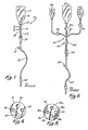
- a multi-fluid infusion system 10 has a fluid reservoir 12, preferably of the collapsible bag type, that is supported above a patient by a rack member (not shown).
- a metering device or drop chamber 14 is connected to reservoir 12 by a supply tube 18 that punctures and extends into reservoir 12.
- a flow control device 20, illustratively shown as a roller clamp, is connected to drop chamber 14 by tubing or conduit 26 and is connected to a feed tube 22 that is configured for insertion into the hub of a catheter or needle inserted into the patient.
- a supplemental administration port 24 in the tubing 26 that connects the flow control device 20 to feed tube 22, is utilized to administer small dosages of medication into the infusion system by the insertion of a hypodermic needle into port 24.
- all of the above components are made of elastomeric material. The components are packaged in a sterilized kit and are disposable after use.
- Drop chamber 14 is comprised of a first, upper member 30 and a second, lower member 32 that are both cylindrical in shape.
- Lower member 32 is partially telescopically received within upper member 30 and is rotatable with respect to upper member 30 forming a selection means generally shown at 40.
- the top portion of lower member 32 is sealed by a mounting plate 36 and the bottom portion thereof defines a fluid outlet 28.
- a plurality of drop tubes 38a, 38b and 38c penetrate through, and are circumferentially spaced around, mounting plate 36, as best seen in Fig. 5.
- Drip tubes 38a-c have lower edge means defining drop forming orifices 39a-c, respectively.
- Each orifice 39a-c has a different cross-sectional area.
- the orifice cross-sectional areas are preselected to produce droplets of various volumes appropriate for the viscosity of the fluids that will be administered with the apparatus, or to infuse greatly varying volumes of the same fluid.
- a fluid inlet 27 forms the top of upper member 30.
- a disk 35 forms the bottom of upper member 30 and is in general abutting relationship with mounting plate 36.
- a discharge opening 42 formed in disk 35 is offset from the central longitudinal axis of members 30, 32 a preselected distance so as to be selectively alignable with one of the drop tubes 38a, 38b or 38c.
- a flexible edge or wiper means 44 formed around opening 42 provides a seal between disk 35 and the selected drop tube to prevent any of the administered fluid from seeping in between disk 35 and mounting plate 36.
- a plurality of downwardly extending debosments 48 are radially spaced around disk 35 in the same general configuration that the drop tubes 38a-c are spaced around mounting plate 36.
- the upper portion of drop tubes 38a, 38b and 38c that protrude through mounting plate 36 are enlarged to approximately the same size as debosments 48.
- a metering chamber 17 below orifices 39a-c has a pliable cylindrical wall 34 that is transparent, to facilitate monitoring of liquid droplets dispensing from the selected orifice as will be described in more detail below.
- the above description apparatus operates as follows. When it is desired to infuse a particular liquid into a patient, a needle or catheter is inserted in the patient and the apparatus is connected in the manner previously described. As is conventional, air must be first evacuated from the apparatus before the apparatus is connected to the patient by flowing fluid through the apparatus until all of the air is expelled. This can advantageously be performed very rapidly with the present invention by setting control device 20 to maximum flow and selectively aligning the discharge opening 42 with drop tube 38a having the largest orifice 39a. This aligning is accomplished by operating selection means 40, i.e., by rotating first member 30 with respect to second member 32, until discharge opening 42 is in alignment with drop tube 38a.
- flow control device 20 is closed and selection means 40 is operated in order to align discharge opening 42 with the drop tube 38a-38c that is appropriate for the fluid to be administered. Once the appropriate selection is effected, flow control device 20 is regulated, while the rate of droplet flow from the selected drop tube orifice through metering chamber 17 is monitored, to establish the desired flow rate. If it is desirable to administer a fluid having a significantly different viscosity to the patient, flow control device 20 is closed off and the fluid reservoir 12 is exchanged for another one having the desired fluid therein.
- Selection means 40 is operated in order to align discharge opening 42 with the drop tube 38a-c having the drop orifice 39 that is appropriate for the viscosity of the fluid that is to be administered and flow control device 20 is regulated while the drop rate is monitored in metering chamber 17.
- orifices 39a-c would have diameters corresponding to 10 drops per cubic centimeter (cc), 15 drops per cc and 60 drops per cc, respectively. Any appropriate drop size orifices could be utilized and the number of drop tubes could be fewer than or more than that shown.
- the decrease in the time required to purge the apparatus of air can be significant. For example, if saline or like solution requiring the smallest orifice is to be administered, the air purging time for conventional infusion apparatus would be approximately 30 seconds.
- the lines can be purged in about 5 seconds and the selection means then operated in order to administer the low viscosity fluid.
- a momentary increase in the rate of flow of the infused fluid can also be of help in forcing medication applied in supplemental administration port 24 to the patient rapidly when desired.
- Fig. 6 shows an arrangement of components according to the present invention when it is contemplated ahead of time that multiple fluids will need to be administered to a patient. Such a situation would typically arise during major surgical treatment in which the patient is stabilized on glucose or saline solution before surgery, is administered whole blood or blood plasma during surgery and may be administered yet another fluid after surgery.
- a plurality of fluid reservoirs 112a-c are each connected to a common connection 54 through a shut off roller clamp or valve 52a-c. Connection 54, in turn, is connected to drop chamber 114.
- fluid reservoir 112a contains saline solution
- reservoir 112b contains whole blood
- reservoir 112c contains glucose.
- clamps 52a, 52b and 52c are initially closed. Clamp 52b will be momentarily opened to purge the short section of tubing from the blood reservoir 112b to common connection 54. Clamp 52b is then closed and clamp 52c momentarily opened in order to purge the tubing from reservoir 112c to the connection 54. Purging is completed by closing valve 52c and opening valve 52a to purge the remainder of the apparatus with the saline solution in reservoir 112a. Assuming that saline solution is the first fluid to be administered, valve 52a is momentarily closed while selection means 140 is adjusted to select the drop tube appropriate for saline solution. Valve 52a is then opened and flow control device 120 adjusted to the desired flow rate by monitoring the drop rate.
- clamp 52a When it then becomes desirable to administer whole blood, clamp 52a is closed and selection means 140 adjusted to select the drop tube appropriate for blood. Clamp 52b is then opened and flow control device 120 adjusted for the appropriate flow. To subsequently administer glucose solution, clamp 52b is closed and selection means 140 adjusted to select the appropriate drop tube. Clamp 52c is then opened and flow control device 120 adjusted.
- the present invention provides multi-liquid infusion capability that greatly reduces the time required to intravenously administer fluids by not only eliminating the requirement to change apparatus every time a different fluid is administered, but also by reducing the amount of time required to establish the apparatus.
- the largest orifice may be used to purge the line of air with subsequent selection of the proper drop setting for infusion.
- wasting precious time that may be lost by the selection of a drop tube that is inappropriate for the desired fluid can be completely eliminated.
- the present apparatus would reduce the cost of administering multiple fluids by requiring that only one apparatus be used on the patient no matter how many different fluids are administered. Inventory costs are also reduced because only one type of apparatus, rather than three or four, need to be maintained in inventory.
- the patient's well-being is enhanced by the reduced risk of infection and the stress associated with the procedure of fluid infusion apparatus changeover.
Landscapes
- Health & Medical Sciences (AREA)
- Biomedical Technology (AREA)
- Hematology (AREA)
- Vascular Medicine (AREA)
- Engineering & Computer Science (AREA)
- Anesthesiology (AREA)
- Physics & Mathematics (AREA)
- Heart & Thoracic Surgery (AREA)
- Fluid Mechanics (AREA)
- Life Sciences & Earth Sciences (AREA)
- Animal Behavior & Ethology (AREA)
- General Health & Medical Sciences (AREA)
- Public Health (AREA)
- Veterinary Medicine (AREA)
- Infusion, Injection, And Reservoir Apparatuses (AREA)
Claims (10)
- Un dispositif de dosage pour un système d'infusion intraveineuse de fluide (10), ledit dispositif de dosage comprenant une chambre de stillation (14) et un moyen de dosage (20) relié par un moyen de communication (29) à ladite chambre de stillation (14) pour doser le débit des gouttelettes qui s'écoulent de la chambre de stillation, la chambre de stillation ayant, à l'intérieur, un moyen de formation de gouttes (39a, 39b, 39c) afin de répartir l'écoulement d'un fluide sous la forme d'une succession de gouttelettes ; caractérisé en ce que ledit moyen de formation de gouttes est réglable grâce à un moyen de sélection (40) associé à ladite chambre de stillation (14) dans le but de produire d'une façon sélective des gouttelettes de taille et de volume différents pour un fluide donné, ledit moyen de sélection (40) pouvant être actionné, pour régler ledit moyen de formation de gouttes, sans déconnecter ladite chambre de stillation (14) dudit moyen de communication (29), la taille et le volume des gouttelettes appropriés à la viscosité du fluide donné qui est administré et à la vitesse de perfusion voulue, pouvant être choisis sans démonter le système et sans le débrancher du patient.
- Un dispositif de dosage selon la revendication 1, dans lequel ledit moyen de formation de gouttes comprend un ensemble de plusieurs tubes de stillation (38a, 38b, 38c), chacun desdits tubes de stillation ayant un orifice (39a-c) dont la surface de la section transversale est différente de celle desdits autres tubes de stillation et ledit moyen de sélection (40) comprenant un moyen d'orientation d'écoulement (42) permettant de diriger le fluide vers l'un desdits tubes de stillation.
- Un dispositif de dosage selon la revendication 2, dans lequel lesdits tubes de stillation (38a-c) sont répartis sur la circonférence d'un cercle ayant un diamètre déterminé et ledit moyen d'orientation d'écoulement comprenant un disque (35) pouvant tourner d'une façon sélective concentriquement audit cercle formé par les tubes (38a-c) est muni d'un orifice d'écoulement (42) qui le traverse et qui peut s'aligner, au choix, avec l'un ou l'autre desdits tubes (38a-c).
- Un dispositif de dosage selon la revendication 3, dans lequel lesdits tubes (38a-c) sont répartis à distances égales sur la circonférence d'un cercle et dans lequel la surface dudit disque (35) présente des bossages (48) répartis sur une même circonférence avec ledit orifice d'écoulement (42) et faisant saillie vers lesdits tubes (38a-c) pour maintenir ledit orifice d'écoulement (42) aligné avec l'un desdits tubes.
- Un dispositif de dosage selon les revendications 3 ou 4, dans lequel des moyens flexibles de recouvrement (44) sont prévus pour former un joint entre ledit orifice d'écoulement (42) et l'un desdits orifices (38a-c).
- Un dispositif de dosage selon l'une des revendications 2 à 5, comprenant un premier élément (30) ayant un orifice d'entrée de fluide (27) et un orifice de sortie (42) ; un second élément (32) ayant une embase (36), un ensemble de plusieurs desdits tubes de stillation (38a-c) étant montés sur ladite embase (36) et un orifice de sortie de fluide (28) ; ainsi que des moyens d'étanchéité (46) entre lesdits éléments (30, 32) pour empêcher l'entrée de toute contamination dans ladite chambre de dosage, le moyen de sélection (40) pouvant être manoeuvré pour aligner d'une façon sélective ledit orifice d'écoulement (42) avec l'un desdits tubes de stillation (38a-c).
- Un dispositif de dosage selon la revendication 6, dans lequel ledit second élément (32) comporte une paroi essentiellement transparente disposée autour desdits tubes de stillation (38a-38c).
- Un dispositif de dosage selon la revendication 6, dans lequel le premier et le second élément (30, 32) comportent des parois cylindriques (30, 32) généralement alignées verticalement le long d'un axe central longitudinal et mobiles en rotation l'un par rapport à l'autre autour dudit axe pour constituer le moyen de sélection (40) permettant l'orientation sélective desdits éléments ; la paroi cylindrique dudit premier élément (30) a une embase circulaire (38) fixée à ladite paroi cylindrique et comportant l'orifice d'écoulement (42), ledit second élément (32) ayant à son sommet une embase (36) fixée à sa paroi cylindrique et venant en contact avec ledit disque (35), l'ensemble desdits tubes de stillation (38a-c) étant monté sur ladite embase (36), et l'orifice de sortie de fluide (28) ainsi que lesdits tubes de stillation (38a-c) étant parallèles audit axe et répartis sur la circonférence d'un cercle centré sur ledit axe, ledit cercle ayant un rayon égal à la distance qui sépare ledit orifice d'écoulement (42) dudit axe.
- Un dispositif de dosage selon la revendication 8, dans lequel la paroi cylindrique dudit second élément (32) est transparente pour donner un moyen de déterminer la vitesse de formation des gouttelettes.
- Un système d'infusion intraveineuse pour administrer à un patient un fluide provenant d'un réservoir de fluide (12) comprenant un dispositif de dosage (14, 20) selon l'une quelconque des revendications qui précèdent, un premier moyen de raccordement (27, 18) permettant de relier le dispositif de dosage audit réservoir de fluide et un second moyen de raccordement (22, 29) permettant de relier le dispositif de dosage à un patient.
Priority Applications (1)
| Application Number | Priority Date | Filing Date | Title |
|---|---|---|---|
| AT88302943T ATE79552T1 (de) | 1987-04-09 | 1988-03-31 | Dosiervorrichtung fuer infusionen mit waehlbarer tropfengroesse. |
Applications Claiming Priority (2)
| Application Number | Priority Date | Filing Date | Title |
|---|---|---|---|
| US07/034,540 US4781698A (en) | 1987-04-09 | 1987-04-09 | Selectable drop size infusion metering device |
| US34540 | 1987-04-09 |
Publications (3)
| Publication Number | Publication Date |
|---|---|
| EP0287247A2 EP0287247A2 (fr) | 1988-10-19 |
| EP0287247A3 EP0287247A3 (en) | 1989-08-02 |
| EP0287247B1 true EP0287247B1 (fr) | 1992-08-19 |
Family
ID=21877061
Family Applications (1)
| Application Number | Title | Priority Date | Filing Date |
|---|---|---|---|
| EP88302943A Expired - Lifetime EP0287247B1 (fr) | 1987-04-09 | 1988-03-31 | Dispositif de dosage pour infusion à taille des gouttes sélectionnable |
Country Status (9)
| Country | Link |
|---|---|
| US (1) | US4781698A (fr) |
| EP (1) | EP0287247B1 (fr) |
| JP (1) | JP2688761B2 (fr) |
| AT (1) | ATE79552T1 (fr) |
| AU (1) | AU610575B2 (fr) |
| CA (1) | CA1289027C (fr) |
| DE (1) | DE3873805T2 (fr) |
| ES (1) | ES2030375T3 (fr) |
| MX (1) | MX167714B (fr) |
Cited By (2)
| Publication number | Priority date | Publication date | Assignee | Title |
|---|---|---|---|---|
| US8784360B2 (en) | 2009-01-21 | 2014-07-22 | Medtronic, Inc. | Catheter systems having flow restrictors |
| US9539382B2 (en) | 2013-03-12 | 2017-01-10 | Medtronic, Inc. | Stepped catheters with flow restrictors and infusion systems using the same |
Families Citing this family (21)
| Publication number | Priority date | Publication date | Assignee | Title |
|---|---|---|---|---|
| NL8702698A (nl) * | 1987-11-11 | 1989-06-01 | Leuven Res & Dev Vzw | Gas-insufflatiesysteem bij endoscopie en een chirurgische endoscoop daarvoor. |
| AU629228B2 (en) * | 1988-07-21 | 1992-10-01 | Macnaught Pty Limited | Improvements relating to infusion devices |
| US5045069A (en) * | 1989-01-17 | 1991-09-03 | Robert Imparato | Portable infusion monitor |
| ES2098349T3 (es) * | 1990-03-08 | 1997-05-01 | Macnaught Pty Ltd | Reguladores de flujo para aparatos de infusion de fluidos. |
| US5057090A (en) * | 1990-06-07 | 1991-10-15 | Bessman Edward S | Drip metering apparatus with selectable drop sizes and coupling arrangement therein |
| US5195987A (en) * | 1991-08-16 | 1993-03-23 | Karpiak Kenneth D | Emergency I.V. set-up apparatus |
| US5201725A (en) * | 1991-09-26 | 1993-04-13 | Ivac | Needle free i.v. adapter |
| US5382230A (en) * | 1991-12-16 | 1995-01-17 | Thomas Jefferson University | Vascular access sheath for interventional devices |
| US5295957A (en) * | 1991-12-23 | 1994-03-22 | Pigeon Co., Ltd. | Breast pump having a pressure adjusting mechanism |
| EP0569728A1 (fr) * | 1992-04-15 | 1993-11-18 | FISHER & PAYKEL LIMITED | Dispositif d'alimentation en liquide |
| US5980489A (en) * | 1992-04-17 | 1999-11-09 | Science Incorporated | Fluid dispenser with fill adapter |
| US6231545B1 (en) | 1996-12-18 | 2001-05-15 | Science Incorporated | Variable rate infusion apparatus with indicator and adjustable rate control |
| DE19709704C2 (de) * | 1997-03-10 | 1999-11-04 | Michael Georgieff | Verwendung einer flüssigen Präparation von Xenon zur intravenösen Verabreichung bei Einleitung und/oder Aufrechterhaltung der Anaesthesie |
| US5910135A (en) * | 1997-03-31 | 1999-06-08 | Innovative Design Associates | Intravenous infusion system |
| US6149631A (en) * | 1999-09-10 | 2000-11-21 | Haydel, Jr.; Leo Joseph | Drip impinging intravenous drip chamber |
| BE1014493A6 (fr) * | 2001-11-23 | 2003-11-04 | Beria Soci T Anonyme | Ligne de perfusion perfectionnee et debitmetre a flotteur pour une ligne de perfusion. |
| KR100578001B1 (ko) * | 2004-05-03 | 2007-11-30 | (주)이화바이오메딕스 | 약액 유량 조절기 |
| KR100592468B1 (ko) * | 2004-09-03 | 2006-06-28 | 김종욱 | 휴대용 수액 주입장치 |
| US20060251405A1 (en) * | 2005-05-09 | 2006-11-09 | Saleh George A | Method of tracking predetermined periods of time while encouraging brand loyalty |
| KR101134279B1 (ko) | 2009-02-09 | 2012-04-10 | (주)이화프레지니우스카비 | 필터장치 및 이를 구비한 주사액 주입장치 |
| CN110038182A (zh) * | 2019-04-04 | 2019-07-23 | 江苏吉春医用器材有限公司 | 一次性使用重力输液器 |
Family Cites Families (22)
| Publication number | Priority date | Publication date | Assignee | Title |
|---|---|---|---|---|
| US2247227A (en) * | 1939-09-23 | 1941-06-24 | Eaton Mfg Co | Valve for automotive vehicle heaters |
| US2576403A (en) * | 1945-07-09 | 1951-11-27 | Kirschenbaum Samuel | Drop device |
| US2812765A (en) * | 1955-12-19 | 1957-11-12 | Benjamin F Tofflemire | Combination aspirator and fluiddelivering surgical instrument |
| FR1347759A (fr) * | 1962-11-15 | 1964-01-04 | Dispositif de reprise, ou d'introduction, d'un liquide dans un récipient hermétique, à débit réglable | |
| US3323774A (en) * | 1963-11-26 | 1967-06-06 | Resiflex Lab | Composite closure-drip chamber-valve means unit for administration of liquids |
| US3298367A (en) * | 1964-01-10 | 1967-01-17 | Richard I Bergman | Apparatus for administering parenteral liquids |
| US3341168A (en) * | 1964-03-25 | 1967-09-12 | Thurston H Toeppen | Apparatus for the controlled distribution of liquids |
| US3517909A (en) * | 1968-04-26 | 1970-06-30 | Deseret Pharma | Valve unit for an intravenous liquid feeding apparatus |
| US3690318A (en) * | 1970-04-16 | 1972-09-12 | Bourns Inc | Apparatus for parenteral fluid infusion provided with variable flow control means |
| US3785378A (en) * | 1972-04-06 | 1974-01-15 | C Stewart | Flow control valve for intravenous fluids |
| JPS5225678B2 (fr) * | 1972-05-29 | 1977-07-08 | ||
| US3877428A (en) * | 1973-04-30 | 1975-04-15 | Sorenson Research Co | Variable infusion control device |
| GB1481427A (en) * | 1973-08-21 | 1977-07-27 | United States Surgical Corp | Measuring chamber arrangement for intravenous set |
| US3880401A (en) * | 1973-10-01 | 1975-04-29 | Harold L Wiltse | Flow metering and shut-off valve |
| US3949966A (en) * | 1975-04-30 | 1976-04-13 | Robertshaw Controls Company | Variable constant flow selector valve |
| CA1061569A (fr) * | 1975-08-25 | 1979-09-04 | Cominco Ltd. | Methode d'extraction des chlorures de cuivre en presence dans des solutions aqueuses |
| US4195631A (en) * | 1978-06-14 | 1980-04-01 | Baucom Keith K | Flow regulating device useable in plasma pheresis |
| CH636271A5 (fr) * | 1979-11-27 | 1983-05-31 | Sideco Etablissement Internati | Dispositif pour regler le debit d'un liquide dans un tuyau. |
| US4317473A (en) * | 1979-12-31 | 1982-03-02 | Becton, Dickinson And Company | Fluid flow control assembly |
| JPS59140737U (ja) * | 1983-03-14 | 1984-09-20 | 株式会社日本メディカル・サプライ | 定量輸液装置 |
| JPS6017751U (ja) * | 1983-07-14 | 1985-02-06 | 塩野義製薬株式会社 | 点滴セツト |
| IL73598A (en) * | 1984-11-23 | 1991-01-31 | Leibinsohn Saul | Fluid control device particularly useful in liquid transfusion apparatus |
-
1987
- 1987-04-09 US US07/034,540 patent/US4781698A/en not_active Expired - Lifetime
-
1988
- 1988-03-31 AT AT88302943T patent/ATE79552T1/de not_active IP Right Cessation
- 1988-03-31 DE DE8888302943T patent/DE3873805T2/de not_active Expired - Fee Related
- 1988-03-31 EP EP88302943A patent/EP0287247B1/fr not_active Expired - Lifetime
- 1988-03-31 ES ES198888302943T patent/ES2030375T3/es not_active Expired - Lifetime
- 1988-03-31 CA CA000563157A patent/CA1289027C/fr not_active Expired - Fee Related
- 1988-04-07 MX MX011028A patent/MX167714B/es unknown
- 1988-04-08 AU AU14454/88A patent/AU610575B2/en not_active Ceased
- 1988-04-08 JP JP63087072A patent/JP2688761B2/ja not_active Expired - Fee Related
Cited By (2)
| Publication number | Priority date | Publication date | Assignee | Title |
|---|---|---|---|---|
| US8784360B2 (en) | 2009-01-21 | 2014-07-22 | Medtronic, Inc. | Catheter systems having flow restrictors |
| US9539382B2 (en) | 2013-03-12 | 2017-01-10 | Medtronic, Inc. | Stepped catheters with flow restrictors and infusion systems using the same |
Also Published As
| Publication number | Publication date |
|---|---|
| JP2688761B2 (ja) | 1997-12-10 |
| EP0287247A2 (fr) | 1988-10-19 |
| DE3873805D1 (de) | 1992-09-24 |
| ATE79552T1 (de) | 1992-09-15 |
| ES2030375T1 (es) | 1992-11-01 |
| US4781698A (en) | 1988-11-01 |
| MX167714B (es) | 1993-04-07 |
| AU1445488A (en) | 1988-10-13 |
| DE3873805T2 (de) | 1993-01-07 |
| CA1289027C (fr) | 1991-09-17 |
| AU610575B2 (en) | 1991-05-23 |
| EP0287247A3 (en) | 1989-08-02 |
| JPH01124469A (ja) | 1989-05-17 |
| ES2030375T3 (es) | 1993-04-01 |
Similar Documents
| Publication | Publication Date | Title |
|---|---|---|
| US4781698A (en) | Selectable drop size infusion metering device | |
| US7789853B2 (en) | Infusion apparatus with constant force spring energy source | |
| EP0340297B1 (fr) | Cartouche d'administration de medicament a couvercle protecteur | |
| US20030212381A1 (en) | Enteral tube feeding device with in-operation cleaning capability | |
| US4573974A (en) | Medical administration set enabling sequential delivery of two liquids at different flow rate | |
| US4534764A (en) | Sequential medication delivery device | |
| US6245041B1 (en) | Fluid dispenser with fill adapter | |
| EP0089404A1 (fr) | Système d'écoulement par gravité pour administrer successivement plusieurs liquides médicaux | |
| JPH0316149B2 (fr) | ||
| AU2922689A (en) | Cartridge and adapter for introducing a beneficial agent into an intravenous delivery system | |
| JPH05506163A (ja) | 流体注入器用流量調整器 | |
| JPS6111055A (ja) | 点滴装置 | |
| US6391006B1 (en) | Fluid delivery apparatus with reservoir fill assembly | |
| US5409477A (en) | Solution administration apparatus with orifice flow control device | |
| US4479793A (en) | Parenteral administration using drug delivery device | |
| EP0435859B1 (fr) | Système d'administration auto-amorçante adapté pour l'addition d'un remède | |
| DK153593B (da) | Apparat til styring af vaeskemaengdestroem, isaer ved intravenoes adminstration af vaeske | |
| US4552556A (en) | Parenteral controlled therapy | |
| US4525162A (en) | Parenteral controlled delivery | |
| EP0462213B1 (fr) | Systeme d'administration intraveineuse d'un agent therapeutique | |
| IL134127A (en) | Manifold for catheterization |
Legal Events
| Date | Code | Title | Description |
|---|---|---|---|
| PUAI | Public reference made under article 153(3) epc to a published international application that has entered the european phase |
Free format text: ORIGINAL CODE: 0009012 |
|
| AK | Designated contracting states |
Kind code of ref document: A2 Designated state(s): AT CH DE ES FR GB IT LI NL SE |
|
| PUAL | Search report despatched |
Free format text: ORIGINAL CODE: 0009013 |
|
| AK | Designated contracting states |
Kind code of ref document: A3 Designated state(s): AT CH DE ES FR GB IT LI NL SE |
|
| 17P | Request for examination filed |
Effective date: 19900109 |
|
| 17Q | First examination report despatched |
Effective date: 19910404 |
|
| GRAA | (expected) grant |
Free format text: ORIGINAL CODE: 0009210 |
|
| AK | Designated contracting states |
Kind code of ref document: B1 Designated state(s): AT CH DE ES FR GB IT LI NL SE |
|
| REF | Corresponds to: |
Ref document number: 79552 Country of ref document: AT Date of ref document: 19920915 Kind code of ref document: T |
|
| ITF | It: translation for a ep patent filed | ||
| REF | Corresponds to: |
Ref document number: 3873805 Country of ref document: DE Date of ref document: 19920924 |
|
| ET | Fr: translation filed | ||
| REG | Reference to a national code |
Ref country code: ES Ref legal event code: FG2A Ref document number: 2030375 Country of ref document: ES Kind code of ref document: T3 |
|
| PLBE | No opposition filed within time limit |
Free format text: ORIGINAL CODE: 0009261 |
|
| STAA | Information on the status of an ep patent application or granted ep patent |
Free format text: STATUS: NO OPPOSITION FILED WITHIN TIME LIMIT |
|
| 26N | No opposition filed | ||
| EAL | Se: european patent in force in sweden |
Ref document number: 88302943.1 |
|
| REG | Reference to a national code |
Ref country code: GB Ref legal event code: IF02 |
|
| PGFP | Annual fee paid to national office [announced via postgrant information from national office to epo] |
Ref country code: GB Payment date: 20050207 Year of fee payment: 18 Ref country code: AT Payment date: 20050207 Year of fee payment: 18 |
|
| PGFP | Annual fee paid to national office [announced via postgrant information from national office to epo] |
Ref country code: NL Payment date: 20050209 Year of fee payment: 18 |
|
| PGFP | Annual fee paid to national office [announced via postgrant information from national office to epo] |
Ref country code: FR Payment date: 20050302 Year of fee payment: 18 |
|
| PGFP | Annual fee paid to national office [announced via postgrant information from national office to epo] |
Ref country code: SE Payment date: 20050303 Year of fee payment: 18 |
|
| PGFP | Annual fee paid to national office [announced via postgrant information from national office to epo] |
Ref country code: CH Payment date: 20050311 Year of fee payment: 18 |
|
| PGFP | Annual fee paid to national office [announced via postgrant information from national office to epo] |
Ref country code: ES Payment date: 20050314 Year of fee payment: 18 |
|
| PGFP | Annual fee paid to national office [announced via postgrant information from national office to epo] |
Ref country code: DE Payment date: 20050331 Year of fee payment: 18 |
|
| PG25 | Lapsed in a contracting state [announced via postgrant information from national office to epo] |
Ref country code: LI Free format text: LAPSE BECAUSE OF NON-PAYMENT OF DUE FEES Effective date: 20060331 Ref country code: GB Free format text: LAPSE BECAUSE OF NON-PAYMENT OF DUE FEES Effective date: 20060331 Ref country code: CH Free format text: LAPSE BECAUSE OF NON-PAYMENT OF DUE FEES Effective date: 20060331 Ref country code: AT Free format text: LAPSE BECAUSE OF NON-PAYMENT OF DUE FEES Effective date: 20060331 |
|
| PGFP | Annual fee paid to national office [announced via postgrant information from national office to epo] |
Ref country code: IT Payment date: 20060331 Year of fee payment: 19 |
|
| PG25 | Lapsed in a contracting state [announced via postgrant information from national office to epo] |
Ref country code: SE Free format text: LAPSE BECAUSE OF NON-PAYMENT OF DUE FEES Effective date: 20060401 Ref country code: ES Free format text: LAPSE BECAUSE OF NON-PAYMENT OF DUE FEES Effective date: 20060401 |
|
| PG25 | Lapsed in a contracting state [announced via postgrant information from national office to epo] |
Ref country code: NL Free format text: LAPSE BECAUSE OF NON-PAYMENT OF DUE FEES Effective date: 20061001 |
|
| PG25 | Lapsed in a contracting state [announced via postgrant information from national office to epo] |
Ref country code: DE Free format text: LAPSE BECAUSE OF NON-PAYMENT OF DUE FEES Effective date: 20061003 |
|
| REG | Reference to a national code |
Ref country code: CH Ref legal event code: PL |
|
| GBPC | Gb: european patent ceased through non-payment of renewal fee |
Effective date: 20060331 |
|
| NLV4 | Nl: lapsed or anulled due to non-payment of the annual fee |
Effective date: 20061001 |
|
| EUG | Se: european patent has lapsed | ||
| REG | Reference to a national code |
Ref country code: FR Ref legal event code: ST Effective date: 20061130 |
|
| REG | Reference to a national code |
Ref country code: ES Ref legal event code: FD2A Effective date: 20060401 |
|
| PG25 | Lapsed in a contracting state [announced via postgrant information from national office to epo] |
Ref country code: FR Free format text: LAPSE BECAUSE OF NON-PAYMENT OF DUE FEES Effective date: 20060331 |
|
| PG25 | Lapsed in a contracting state [announced via postgrant information from national office to epo] |
Ref country code: IT Free format text: LAPSE BECAUSE OF NON-PAYMENT OF DUE FEES Effective date: 20070331 |