EP0287319B1 - Chemisches Energie-Speicher-System - Google Patents
Chemisches Energie-Speicher-System Download PDFInfo
- Publication number
- EP0287319B1 EP0287319B1 EP88303262A EP88303262A EP0287319B1 EP 0287319 B1 EP0287319 B1 EP 0287319B1 EP 88303262 A EP88303262 A EP 88303262A EP 88303262 A EP88303262 A EP 88303262A EP 0287319 B1 EP0287319 B1 EP 0287319B1
- Authority
- EP
- European Patent Office
- Prior art keywords
- liquid
- space
- solution
- vessel
- pumping
- Prior art date
- Legal status (The legal status is an assumption and is not a legal conclusion. Google has not performed a legal analysis and makes no representation as to the accuracy of the status listed.)
- Expired - Lifetime
Links
- 238000004146 energy storage Methods 0.000 title claims description 13
- 239000000126 substance Substances 0.000 title description 2
- 239000007788 liquid Substances 0.000 claims description 54
- XLYOFNOQVPJJNP-UHFFFAOYSA-N water Substances O XLYOFNOQVPJJNP-UHFFFAOYSA-N 0.000 claims description 37
- 238000001816 cooling Methods 0.000 claims description 26
- 238000000034 method Methods 0.000 claims description 17
- 238000005086 pumping Methods 0.000 claims description 16
- 238000010438 heat treatment Methods 0.000 claims description 13
- 239000000203 mixture Substances 0.000 claims description 12
- 239000006193 liquid solution Substances 0.000 claims description 11
- KWGKDLIKAYFUFQ-UHFFFAOYSA-M lithium chloride Chemical compound [Li+].[Cl-] KWGKDLIKAYFUFQ-UHFFFAOYSA-M 0.000 claims description 11
- 150000001875 compounds Chemical class 0.000 claims description 10
- AMXOYNBUYSYVKV-UHFFFAOYSA-M lithium bromide Chemical compound [Li+].[Br-] AMXOYNBUYSYVKV-UHFFFAOYSA-M 0.000 claims description 10
- PEDCQBHIVMGVHV-UHFFFAOYSA-N Glycerine Chemical compound OCC(O)CO PEDCQBHIVMGVHV-UHFFFAOYSA-N 0.000 claims description 9
- 239000003507 refrigerant Substances 0.000 claims description 8
- 238000004378 air conditioning Methods 0.000 claims description 7
- 238000004891 communication Methods 0.000 claims description 7
- UXVMQQNJUSDDNG-UHFFFAOYSA-L Calcium chloride Chemical compound [Cl-].[Cl-].[Ca+2] UXVMQQNJUSDDNG-UHFFFAOYSA-L 0.000 claims description 6
- 239000003513 alkali Substances 0.000 claims description 6
- 229910001854 alkali hydroxide Inorganic materials 0.000 claims description 6
- 229910001860 alkaline earth metal hydroxide Inorganic materials 0.000 claims description 6
- 229910001628 calcium chloride Inorganic materials 0.000 claims description 6
- 239000001110 calcium chloride Substances 0.000 claims description 6
- LYCAIKOWRPUZTN-UHFFFAOYSA-N ethylene glycol Natural products OCCO LYCAIKOWRPUZTN-UHFFFAOYSA-N 0.000 claims description 6
- WGCNASOHLSPBMP-UHFFFAOYSA-N hydroxyacetaldehyde Natural products OCC=O WGCNASOHLSPBMP-UHFFFAOYSA-N 0.000 claims description 5
- LFQSCWFLJHTTHZ-UHFFFAOYSA-N Ethanol Chemical compound CCO LFQSCWFLJHTTHZ-UHFFFAOYSA-N 0.000 claims description 4
- 229910001622 calcium bromide Inorganic materials 0.000 claims description 4
- WGEFECGEFUFIQW-UHFFFAOYSA-L calcium dibromide Chemical compound [Ca+2].[Br-].[Br-] WGEFECGEFUFIQW-UHFFFAOYSA-L 0.000 claims description 4
- 125000004432 carbon atom Chemical group C* 0.000 claims description 4
- -1 glycol ethers Chemical class 0.000 claims description 4
- 230000008901 benefit Effects 0.000 claims description 3
- 238000007599 discharging Methods 0.000 claims description 3
- 238000005507 spraying Methods 0.000 claims 4
- 230000000153 supplemental effect Effects 0.000 claims 2
- 239000000243 solution Substances 0.000 description 22
- 239000012071 phase Substances 0.000 description 12
- 239000007864 aqueous solution Substances 0.000 description 9
- 239000007921 spray Substances 0.000 description 9
- OKKJLVBELUTLKV-UHFFFAOYSA-N Methanol Chemical compound OC OKKJLVBELUTLKV-UHFFFAOYSA-N 0.000 description 6
- HEMHJVSKTPXQMS-UHFFFAOYSA-M Sodium hydroxide Chemical compound [OH-].[Na+] HEMHJVSKTPXQMS-UHFFFAOYSA-M 0.000 description 6
- 150000001298 alcohols Chemical class 0.000 description 3
- 238000005260 corrosion Methods 0.000 description 3
- 230000007797 corrosion Effects 0.000 description 3
- 239000000463 material Substances 0.000 description 3
- QGZKDVFQNNGYKY-UHFFFAOYSA-N Ammonia Chemical compound N QGZKDVFQNNGYKY-UHFFFAOYSA-N 0.000 description 2
- XTHFKEDIFFGKHM-UHFFFAOYSA-N Dimethoxyethane Chemical compound COCCOC XTHFKEDIFFGKHM-UHFFFAOYSA-N 0.000 description 2
- WHXSMMKQMYFTQS-UHFFFAOYSA-N Lithium Chemical compound [Li] WHXSMMKQMYFTQS-UHFFFAOYSA-N 0.000 description 2
- 230000005494 condensation Effects 0.000 description 2
- 238000009833 condensation Methods 0.000 description 2
- 239000002826 coolant Substances 0.000 description 2
- XLYOFNOQVPJJNP-UHFFFAOYSA-M hydroxide Chemical compound [OH-] XLYOFNOQVPJJNP-UHFFFAOYSA-M 0.000 description 2
- 239000012266 salt solution Substances 0.000 description 2
- RRQYJINTUHWNHW-UHFFFAOYSA-N 1-ethoxy-2-(2-ethoxyethoxy)ethane Chemical compound CCOCCOCCOCC RRQYJINTUHWNHW-UHFFFAOYSA-N 0.000 description 1
- CPELXLSAUQHCOX-UHFFFAOYSA-M Bromide Chemical compound [Br-] CPELXLSAUQHCOX-UHFFFAOYSA-M 0.000 description 1
- OYPRJOBELJOOCE-UHFFFAOYSA-N Calcium Chemical compound [Ca] OYPRJOBELJOOCE-UHFFFAOYSA-N 0.000 description 1
- DGAQECJNVWCQMB-PUAWFVPOSA-M Ilexoside XXIX Chemical compound C[C@@H]1CC[C@@]2(CC[C@@]3(C(=CC[C@H]4[C@]3(CC[C@@H]5[C@@]4(CC[C@@H](C5(C)C)OS(=O)(=O)[O-])C)C)[C@@H]2[C@]1(C)O)C)C(=O)O[C@H]6[C@@H]([C@H]([C@@H]([C@H](O6)CO)O)O)O.[Na+] DGAQECJNVWCQMB-PUAWFVPOSA-M 0.000 description 1
- FYYHWMGAXLPEAU-UHFFFAOYSA-N Magnesium Chemical compound [Mg] FYYHWMGAXLPEAU-UHFFFAOYSA-N 0.000 description 1
- ZLMJMSJWJFRBEC-UHFFFAOYSA-N Potassium Chemical compound [K] ZLMJMSJWJFRBEC-UHFFFAOYSA-N 0.000 description 1
- 239000000654 additive Substances 0.000 description 1
- 125000002947 alkylene group Chemical group 0.000 description 1
- 229910021529 ammonia Inorganic materials 0.000 description 1
- 229910052792 caesium Inorganic materials 0.000 description 1
- TVFDJXOCXUVLDH-UHFFFAOYSA-N caesium atom Chemical compound [Cs] TVFDJXOCXUVLDH-UHFFFAOYSA-N 0.000 description 1
- 229910052791 calcium Inorganic materials 0.000 description 1
- 239000011575 calcium Substances 0.000 description 1
- 239000012141 concentrate Substances 0.000 description 1
- 239000000110 cooling liquid Substances 0.000 description 1
- 239000000498 cooling water Substances 0.000 description 1
- 229940019778 diethylene glycol diethyl ether Drugs 0.000 description 1
- 238000010790 dilution Methods 0.000 description 1
- 239000012895 dilution Substances 0.000 description 1
- 230000009977 dual effect Effects 0.000 description 1
- 230000007613 environmental effect Effects 0.000 description 1
- 238000001704 evaporation Methods 0.000 description 1
- 230000008020 evaporation Effects 0.000 description 1
- 239000012530 fluid Substances 0.000 description 1
- 239000013529 heat transfer fluid Substances 0.000 description 1
- 150000004679 hydroxides Chemical class 0.000 description 1
- 229910017053 inorganic salt Inorganic materials 0.000 description 1
- 239000007791 liquid phase Substances 0.000 description 1
- 229910052744 lithium Inorganic materials 0.000 description 1
- 229910052749 magnesium Inorganic materials 0.000 description 1
- 239000011777 magnesium Substances 0.000 description 1
- 229910052751 metal Inorganic materials 0.000 description 1
- 239000002184 metal Substances 0.000 description 1
- 150000002739 metals Chemical class 0.000 description 1
- 239000003595 mist Substances 0.000 description 1
- 150000002823 nitrates Chemical class 0.000 description 1
- 239000006259 organic additive Substances 0.000 description 1
- 229910052700 potassium Inorganic materials 0.000 description 1
- 239000011591 potassium Substances 0.000 description 1
- 150000003839 salts Chemical class 0.000 description 1
- 229910052708 sodium Inorganic materials 0.000 description 1
- 239000011734 sodium Substances 0.000 description 1
- 239000007787 solid Substances 0.000 description 1
- 239000002904 solvent Substances 0.000 description 1
- 238000001179 sorption measurement Methods 0.000 description 1
- 239000011232 storage material Substances 0.000 description 1
- 229910052712 strontium Inorganic materials 0.000 description 1
- CIOAGBVUUVVLOB-UHFFFAOYSA-N strontium atom Chemical compound [Sr] CIOAGBVUUVVLOB-UHFFFAOYSA-N 0.000 description 1
- 238000009423 ventilation Methods 0.000 description 1
- 239000002918 waste heat Substances 0.000 description 1
Images
Classifications
-
- F—MECHANICAL ENGINEERING; LIGHTING; HEATING; WEAPONS; BLASTING
- F28—HEAT EXCHANGE IN GENERAL
- F28D—HEAT-EXCHANGE APPARATUS, NOT PROVIDED FOR IN ANOTHER SUBCLASS, IN WHICH THE HEAT-EXCHANGE MEDIA DO NOT COME INTO DIRECT CONTACT
- F28D5/00—Heat-exchange apparatus having stationary conduit assemblies for one heat-exchange medium only, the media being in contact with different sides of the conduit wall, using the cooling effect of natural or forced evaporation
- F28D5/02—Heat-exchange apparatus having stationary conduit assemblies for one heat-exchange medium only, the media being in contact with different sides of the conduit wall, using the cooling effect of natural or forced evaporation in which the evaporating medium flows in a continuous film or trickles freely over the conduits
-
- F—MECHANICAL ENGINEERING; LIGHTING; HEATING; WEAPONS; BLASTING
- F25—REFRIGERATION OR COOLING; COMBINED HEATING AND REFRIGERATION SYSTEMS; HEAT PUMP SYSTEMS; MANUFACTURE OR STORAGE OF ICE; LIQUEFACTION SOLIDIFICATION OF GASES
- F25B—REFRIGERATION MACHINES, PLANTS OR SYSTEMS; COMBINED HEATING AND REFRIGERATION SYSTEMS; HEAT PUMP SYSTEMS
- F25B17/00—Sorption machines, plants or systems, operating intermittently, e.g. absorption or adsorption type
- F25B17/02—Sorption machines, plants or systems, operating intermittently, e.g. absorption or adsorption type the absorbent or adsorbent being a liquid, e.g. brine
-
- F—MECHANICAL ENGINEERING; LIGHTING; HEATING; WEAPONS; BLASTING
- F28—HEAT EXCHANGE IN GENERAL
- F28D—HEAT-EXCHANGE APPARATUS, NOT PROVIDED FOR IN ANOTHER SUBCLASS, IN WHICH THE HEAT-EXCHANGE MEDIA DO NOT COME INTO DIRECT CONTACT
- F28D20/00—Heat storage plants or apparatus in general; Regenerative heat-exchange apparatus not covered by groups F28D17/00 or F28D19/00
- F28D20/003—Heat storage plants or apparatus in general; Regenerative heat-exchange apparatus not covered by groups F28D17/00 or F28D19/00 using thermochemical reactions
-
- Y—GENERAL TAGGING OF NEW TECHNOLOGICAL DEVELOPMENTS; GENERAL TAGGING OF CROSS-SECTIONAL TECHNOLOGIES SPANNING OVER SEVERAL SECTIONS OF THE IPC; TECHNICAL SUBJECTS COVERED BY FORMER USPC CROSS-REFERENCE ART COLLECTIONS [XRACs] AND DIGESTS
- Y02—TECHNOLOGIES OR APPLICATIONS FOR MITIGATION OR ADAPTATION AGAINST CLIMATE CHANGE
- Y02E—REDUCTION OF GREENHOUSE GAS [GHG] EMISSIONS, RELATED TO ENERGY GENERATION, TRANSMISSION OR DISTRIBUTION
- Y02E60/00—Enabling technologies; Technologies with a potential or indirect contribution to GHG emissions mitigation
- Y02E60/14—Thermal energy storage
Definitions
- the present invention is directed to a method of operating a thermal energy storage system.
- thermal energy storage systems With the high cost of electrical energy required to operate air conditioners or heat pumps for cooling buildings, and particularly with the heavy demands for commercial building cooling systems at peak use hours, attention has been directed to various types of thermal energy storage systems. Such energy storage is advantageous since the building cooling and/or heating and process cooling may be generated and stored during off-peak hours at night when most businesses are normally closed, with the ambient outside temperatures being cooler and municipal power requirements reduced.
- thermal energy storage systems are based on a solid to liquid Phase change using energy storage in a narrow temperature range.
- Water based systems using ice storage are especially desirable because of low fluid costs and availability.
- the disadvantages of such systems include low evaporator temperature requirements because thermal gradient forces evaporator temperatures to a level far below 0°C, also reducing the chiller efficiency, incomplete or low phase change, often in the order of about 50% to 55%, and low overall energy density of 186 KJ/kg.
- water is preferred above more corrosive, volatile, expensive and less readily available energy storage materials.
- JP-A-57-117745 discloses a thermal energy storage system having a first vessel containing an aqueous solution of an inorganic salt, and a second vessel containing water. The vessels are connected by a pipe having a closure valve therein.
- heat from a solar collector is used to concentrate the salt solution, steam produced from the first vessel being condensed in the second vessel.
- water in the second vessel is heated and steam therefrom condensed in the first vessel thereby producing heat through dilution of the concentrated solution.
- water in the second vessel is cooled.
- the method utilizes a system with relatively low cost and simple apparatus for taking advantage of the energy storage combined with state of the art heat exchange equipment normally found in modern residential and commercial buildings.
- a method of operating a thermal energy storage system comprising a first vessel containing a liquid solution of a compound selected from the group consisting of alkali and alkaline earth metal hydroxides, lithium chloride, lithium bromide, calcium chloride, calcium bromide and mixtures thereof, and a first space above the level of said liquid solution; a second vessel containing said liquid without said compound therein, and a second space above the level of said liquid; both said first and second vessels being closed to atmosphere and capable of holding a vacuum, conduit means communicating between said first space and said second space for allowing liquid vapour and pressure changes to pass therebetween, and valve means co-operating with said conduit means for controlling communication between said spaces the method comprising charging the system by the steps of
- the invention also provides apparatus used in the method and including a first vessel or chamber containing a liquid solution of a compound selected from the group consisting of alkali and alkaline earth metal hydroxide, lithium chloride, lithium bromide, calcium chloride and calcium bromide, and mixtures thereof said solution having an initial concentration of between about 30% and about 70%, by weight of said compound, said liquid selected from the group consisting of water, an alcohol having between 1 and 8 carbon atoms and, glycerol and glycol ethers, and a first space above the level of said liquid solution; a second vessel or chamber containing said liquid without said compound therein, and a second space above the level of said liquid; both said first and second vessels being closed to atmosphere and capable of holding a vacuum, conduit means communicating between said first space and second space allowing liquid vapour and pressure changes to pass therebetween, and valve means cooperating with said conduit means and controlling communication between said spaces, said apparatus further comprising first heat exchange means cooperating with said first vessel and through which said solution passes, second heat exchange means cooperating with said second
- the energy storage system is charged by heating an aqueous salt solution and cooling water in separate vessels to a liquid temperature differential of at least 16.6°C and preferably 27.7°C or more up to about 100°C differential.
- the vessels are separated although the space above each liquid in the respective vessels are in communication until the desired vapor mass transfer is completed. Thereafter the spatial communication is terminated until it is desired to discharge the energy stored in the system as will be described hereinafter.
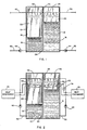
- FIG. 1 there is shown an illustration of a first embodiment of the chemical thermal storage system.
- the apparatus illustrated schematically comprises a container 10 having two cavities or vessels 12 and 14 separated by a baffle or wall 24.
- the container must be air-tight so that the two cells or cavities can selectively maintain different vapor pressures.
- a single container 10 is shown having the two vessels, different containers may be used, the important consideration being that two vessels or cavities are required for holding two different liquids of the system with means for transferring water vapor and communicating vapor pressure differentials between the vessels.
- a valve 26 communicates between the spaces of the two vessels above the liquid levels.
- the valve conveniently located in wall 24, is preferably a butterfly valve with an orifice of several inches and associated with convenient means for opening and closing the valve.
- a first liquid composition 16 is located in first vessel 12 and fills the cavity only partially leaving a space 20 above the liquid level.
- liquid 18 only partially fills the cavity leaving a second space 22 above the liquid level. It is the spaces 20 and 22 which are in communication via valve 26 which can be selectively opened or closed to allow for water vapor to pass between the two spaces thereby maintaining vapor pressure differential between the two vessels when the valve is closed.
- first vessel 12 is a liquid solution of an alkali or alkaline earth metal hydroxide or lithium or calcium chloride or bromide or mixtures thereof having initial concentrations of between about 30 and about 70%, and preferably between about 40% and 60%, by weight.
- second vessel 14 is liquid 18.
- the preferred solvent in vessel 12 and liquid in vessel 14 is water although lower alcohols, glycerol, alkylene, glycol ethers and aqueous solutions or mixtures thereof may also be used. Lower alcohols are those having between 1 and 8 carbon atoms with methanol and ethanol being preferred.
- Suitable glycol ethers include ethylene glycol dimethyl ether, diethylene glycol diethyl ether, etc.
- Most preferred salts are the alkali or alkaline earth metal hydroxides especially those of sodium, potassium, cesium, magnesium, lithium, strontium and calcium. Mixtures of these hydroxides may also be used together with lithium chloride or lithium bromide or calcium chloride as well as nitrate salts of those metals as corrosion suppressing additives, in systems where corrosion may be a problem.
- Organic additives such as long chain alcohols having 7-12 carbon atoms or glycol and its derivatives may be used to increase the sorption rates, increase the differential pressure and serve as freeze point suppressants in vessels 12 and 14.
- plastic vessels or containers which are resistant to the aqueous hydroxide solutions are to be used as are plastic tubing or conduits. Other materials that are lined or coated with compositions which are not susceptible to corrosion when exposed to the strong hydroxide compositions may be used.
- the apparatus also includes suitable conduits, pumps and spray nozzle systems for handling the liquids in the respective cavities.
- conduits 30 and 32, and pump 34 direct aqueous solution 16 from vessel 12 to a heat exchanger, for example, a condenser of a heat pump or chiller or a waste heat source (not shown) for heating the solution to a desired temperature of at least 16.6°C and preferably at least 27.7°C higher than the temperature of water in second vessel 14.
- Preferred solution temperatures are between about 29.4°C and about 54.4°C although higher temperatures may be used.
- the heated solution is then directed to first space 20.
- a preferred method of returning the heated aqueous solution to the first vessel incorporates a nozzle or spray nozzle system 36 which simply sprays the heated aqueous composition in the form of droplets or a fine mist into first space 20 above the surface of liquid 16 in vessel 12. Any suitable spray nozzle means may be used for this purpose.
- water 18 is pumped to a heat exchanger by pump 44 via line 42 where it is cooled, for example, by an air conditioning or heat pump evaporator, cooling tower or other evaporative cooling means or an air to air means after which the cooled water is directed via pipe 40 to second space 22 above the water level using a spray nozzle means 46.
- aqueous solution 16 is heated with condenser heat from a building heat pump system, or otherwise heated conveniently to a temperature of above about 29.4°C up to about 54.4°C
- water 18 is cooled to a temperature of below about 12.7°C and preferably below 16°C using an evaporator from a building heat pump or air conditioning system.
- the solution will desorb water in the form of water vapor via open valve 26 into second space 22 which condenses into the liquid water 18. This process continues until a solution concentration of approximately 52% of NaOH, by weight, is achieved. At that point, the system is charged, and valve 26 is closed to separate the first and second spaces in the two vessels and maintain vapor pressure differential which thereby allows the charged system to remain stored for an indefinite period of time.
- the cold water is circulated to a heat exchanger for the building, for example, passed through a cooling coil in an air handler for cooling the building.
- a cooling coil in an air handler for cooling the building.
- the water is pumped via pipe 42 using pump 44 to the building air handler or other heat exchange cooling means, and returned via pipe 40 to second vessel 14 using the spray nozzle device 46.
- the water thus becomes heated as it absorbs or picks up building heat through the heat transfer system during this discharge phase.
- hot aqueous solution 16 is pumped via pipe 32 and pump 34 to outside air heat exchangers or coolers such as evaporative coolers, cooling towers and the like thereby cooling the aqueous solution which is then returned via pipe 30 and discharged into first space 20 using a spray apparatus 36.
- outside air heat exchangers or coolers such as evaporative coolers, cooling towers and the like thereby cooling the aqueous solution which is then returned via pipe 30 and discharged into first space 20 using a spray apparatus 36.
- valve 26 must be opened and because of the difference in vapor pressure between the first and second spaces, 20 and 22 respectively, water is evaporated in second space 22 to provide substantial cooling of the liquid in second vessel 14.
- the evaporated water is passed into first space 20 where it is absorbed into solution 16, which causes a heat of condensation and solutions in first vessel 12, which heat is again exchanged by the outside cooling means (not shown) previously discussed.
- the heat of condensation and solutions in first vessel 12 may be used for heating purposes, for example in a dual temperature storage capability for building heating and cooling.
- Fig. 2 there is illustrated another variation or embodiment of a system in which a coolant, such as a refrigerant may be directly cooled or condensed at low temperature during discharge of the energy storage system of the invention.
- a container 10 having two vessels or cavities as illustrated in Fig. 1 may be used with a divider 24 separating the two cavities.
- the liquid solution 16 and water 18 in the respective containers are substantially like that previously described as is the change of vapor pressure and exchange of water vapor between the cavities 20 and 22, respectively, through valve 26, in both the charging and discharging phases of the operation of the system.
- the water is cooled during the charging phase by direct exposure to evaporator coils of an air conditioning system evaporator.
- the air conditioning system of the building may utilize a cooling conduit 66 which is exposed directly in second cavity 22 through which cold refrigerant is directed during the charging phase.
- water 18 will be pumped via pump 60 and conduit 58 and sprayed through spray nozzle apparatus 46 over the cold pipe or coil 66 to be cooled.
- aqueous solution 16 is heated by pumping the solution via pump 54 and conduit 52 through spray nozzle apparatus 36 over heated pipe or coils 56 from a condenser 75 or other heating means including a heat exchanger of the HVAC (heating ventilation air conditioning) equipment condensing the refrigerant.
- hot refrigerant may be directed into pipe or coil 56 via pump 74 from the heat exchanger 75.
- valve 26 During discharge, valve 26 is opened, and the respective liquids are pumped through their respective nozzle sprayers over the heat exchange conduits present in the spaces in the respective vessel.
- Refrigerant directed via conduit or coil 66 is cooled by evaporation of water as water is sprayed over the coil in space 22, the water gradually becoming heated at it picks up heat as it cools the refrigerant from heat exchanger 72.
- heat from solution 16 is removed by heat exchanger 75 which similarly pumps a coolant via coil 56 present in space 20.
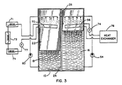
- FIG. 3 A third apparatus configuration utilizing an indirect heat transfer system is illustrated in Fig. 3.
- a heat exchanger 76 is used for directly heating and cooling liquid 16 in the charge and discharge phases, respectively of the operation of the system by pumping a heat transfer fluid with pump 74.
- the heat exchanger illustrated utilizing water with the system is somewhat different in that pump 77 will direct a heat transfer material such as water, ammonia, methanol, glycol-water mixtures, and the like through remote heat exchanger 71, 73 and 79 at various locations throughout a building in which the system is to operate.
- Pump 77 simply pumps the secondary cooling material via pipe 70 to the respective heat exchangers, with the pipe 70 being exposed in space 22 over which water is sprayed as previously discussed regarding the apparatus shown in Fig. 2.
Landscapes
- Engineering & Computer Science (AREA)
- Physics & Mathematics (AREA)
- Thermal Sciences (AREA)
- Mechanical Engineering (AREA)
- General Engineering & Computer Science (AREA)
- Chemical & Material Sciences (AREA)
- Chemical Kinetics & Catalysis (AREA)
- General Chemical & Material Sciences (AREA)
- Sorption Type Refrigeration Machines (AREA)
- Hybrid Cells (AREA)
Claims (6)
- Verfahren zum Betreiben eines chemischen Energiespeichersystems mit
einem ersten Behälter (12) mit einer flüssigen Lösung (16) einer Verbindung aus der Gruppe bestehend aus Hydroxiden von Alkali- und Erdalkalimetallen, Lithiumchlorid, Lithiumbromid, Kalziumchlorid, Kalziumbromid und Gemischen daraus, und einem sich über dem Pegel der flüssigen Lösung befindlichen ersten Raum (20);
einem zweiten Behälter (14), der die Flüssigkeit (18) ohne die Verbindung enthält, und einem sich über dem Pegel der Flüssigkeit befindlichen zweiten Raum (22);
wobei der erste und der zweite Behälter (12, 14) umgebungsdicht verschlossen sind und ein Vakuum halten können, wobei Verbindungsleitungen vorgesehen sind, die den ersten Raum (20) mit dem zweiten Raum (22) verbinden, um Flüssigkeitsdampf und Druckänderungen darin weiterzuleiten und wobei eine Ventileinrichtung (26) vorgesehen ist, die mit den Verbindungsleitungen zusammenwirkt um eine Kommunikation zwischen den Räumen (20, 22) zu regeln, und
wobei das Verfahren das Beladen des Systems mit folgenden Verfahrensschritten umfaßt:a) Öffnen der Ventileinrichtung (26);b1) Erwärmen der Lösung (16) von Umgebungstemperatur auf eine Temperatur über in etwa 29.4°C, wobei von dieser Lösung stammender Dampf aus dem ersten Raum (20) durch die Verbindungsleitung in den zweiten Raum (22) strömt und die Flüssigkeit (18) gleichzeitig von Umgebungstemperatur auf eine Temperatur unter in etwa 12.7°C abgekühlt wird,c) Beenden des Erwärmungs- und des Abkühlvorganges, sobald die Konzentration der Lösung (16) um etwa 6% bis 25% höher ist als die Anfangskonzentration der Lösung; und Beenden des Pumpvorganges; undd) Schließen der Ventileinrichtung,wobei das Verfahren desweiteren das Entladen des Systems mit folgenden Verfahrensschritten umfaßte) Öffnen der Ventileinrichtung (26) zur WeiterLeitung des Dampfes aus dem zweiten Raum (22) in den ersten Raum (20) ,f1) Zuführen der Lösung (16) zu einem ersten Wärmetauscher zur Gewinnung von Wärme, während die Flüssigkeit (18) gleichzeitig einem zweiten Wärmetauscher zugeleitet wird, um die aus der gekühlten Flüssigkeit gewonne thermische Energie dazu zu nutzen, eine Klimaanlage, eine Wärmepumpe oder ein Kühlaggregat zu kühlen;g) Schließen der Ventileinrichtung (26) und Beenden des Pumpvorganges, sobald Lösung und Flüssigkeit sich der Umgebungstemperatur nähern. - Verfahren nach Patentanspruch 1 mit folgenden Zwischenschritten:b2) Weiterleiten der Lösung (16) und der Flüssigkeit (18) an eine erste bzw. zweite Verteilereinrichtung (36, 46), die im ersten Raum (20) bzw. im zweiten Raum (22) vorgesehen ist, und Versprühen der Lösung und der Flüssigkeit von den Verteilereinrichtungen (36, 46) aus; undb2) Weiterleiten der Lösung (16) und der Flüssigkeit (18) an eine erste bzw. zweite Verteilereinrichtung (36, 46), die im ersten Raum (20) bzw. im zweiten Raum (22) vorgesehen ist, und Versprühen der Lösung und der Flüssigkeit von den Verteilereinrichtungen (36, 46) aus.
- Verfahren nach Patentanspruch 2 mit folgenden weiteren Zwischenschritten:b3) Versprühen der Lösung und der Flüssigkeit über den jeweiligen Wärmetauscher (56, 66, 70); undf3) Versprühen der Lösung und der Flüssigkeit über den jeweiligen Wärmetauscher (56, 66, 70).
- Vorrichtung zur Verwendung nach dem Verfahren aus einem der Ansprüche 1 bis 3, mit
einem ersten Behälter oder einer Kammer (12) mit einer flüssigen Lösung (16) einer Verbindung aus der Gruppe bestehend aus den Hydroxiden von Alkali- und Erdalkalimetallen, Lithiumchlorid, Lithiumbromid, Kalziumchlorid und Kalziumbromid und Gemischen daraus, wobei die Losung eine Anfangskonzentration zwischen etwa 30 Gew.-% und etwa 70 Gew.-% aufweist und wobei die aus der Gruppe ausgewählte Flüssigkeit aus Wasser, einem Alkohol, der zwischen 1 und 8 Kohlenstoffatome besitzt, Glycerin und Glykolether besteht, und einem sich über dem Pegel der flüssigen Lösung (16) ausgebildeten ersten Raum (20);
einem zweiten Behälter oder einer zweiten Kammer (14) mit der Flüssigkeit (18) ohne die Verbindung, und einem sich über dem Pegel der Flüssigkeit (18) befindlichen zweiten Raum (22);
wobei sowohl der erste als auch der zweite Behälter (12, 14) umgebungsdicht verschlossen ist und ein Vakuum halten kann, wobei Leitungen vorgesehen sind, die eine Verbindung zwischen dem ersten Raum (20) und dem zweiten Raum (22) herstellen, so daß Dampf und Druckänderungen darin weitergeleiten werden können, und wobei eine Ventileinrichtung (26) vorgesehen ist, die mit den Leitungen zusammenwirken und die Kommunikation zwischen den beiden Räumen (20, 22) regelt;
wobei die Vorrichtung des weiteren folgendes umfaßt:
einen ersten Wärmeaustauscher, der mit dem ersten Behälter 12 wirkverbunden ist und den die Lösung durchfließt;
einen zweiten Wärmeaustauscher, der mit dem zweiten Behälter (14) wirkverbunden ist und den die Flüssigkeit durchfließt;
eine erste Pumpeinrichtung (34), die die Lösung (16) zur Verteilereinrichtung (36) fördert und die Lösung in den ersten Raum (20) leitet; und
eine zweite Pumpeinrichtung (44), die die Flüssigkeit (18) zur Verteilereinrichtung (46) fördert und die Flüssigkeit in den zweiten Raum (22) leitet. - Vorrichtung nach Anspruch 4, wobei der der erste Wärmetauscher eine Verdampfungskühlung oder eine Luft-Luft-Kühlung (75, 76), eine erste zusätzliche Wärmeübertragungseinrichtung mit einer ersten Leitungsschleife mit einer darin befindlichen wärmeübertragenden Flüssigkeit und eine damit kooperierende Pumpe (74) aufweist, die die wärmeübertragende Flüssigkeit durch die Leitungsschleife pumpt, wobei sich die Leitungsschleife zwischen dem ersten Raum (20) und der Verdampfungs- oder Luft-Luft-Kühlung (75, 76) erstreckt.
- Vorrichtung nach Anspruch 4 oder 5, wobei der zweite Wärmetauscher einen Wärmepumpenverdampfer (71, 73, 79; 72) und eine zweite zusätzliche Wärmeübertragungseinrichtung mit einer zweiten Leitungsschleife mit einer darin befindlichen wärmeübertragenden Flüssigkeit und eine damit kooperierenden Pumpe (77) aufweist, die die wärmeübertragende Flüssigkeit durch die Leitungsschleife pumpt, wobei sich die zweite Leitungsschleife zwischen dem zweiten Raum (22) und dem Verdampfer (71, 73, 79, 72) erstreckt.
Applications Claiming Priority (2)
| Application Number | Priority Date | Filing Date | Title |
|---|---|---|---|
| US3832387A | 1987-04-14 | 1987-04-14 | |
| US38323 | 1987-04-14 |
Publications (2)
| Publication Number | Publication Date |
|---|---|
| EP0287319A1 EP0287319A1 (de) | 1988-10-19 |
| EP0287319B1 true EP0287319B1 (de) | 1992-11-11 |
Family
ID=21899294
Family Applications (1)
| Application Number | Title | Priority Date | Filing Date |
|---|---|---|---|
| EP88303262A Expired - Lifetime EP0287319B1 (de) | 1987-04-14 | 1988-04-12 | Chemisches Energie-Speicher-System |
Country Status (5)
| Country | Link |
|---|---|
| US (2) | US4823864A (de) |
| EP (1) | EP0287319B1 (de) |
| AU (1) | AU604871B2 (de) |
| DE (1) | DE3875779T2 (de) |
| ES (1) | ES2036677T3 (de) |
Families Citing this family (31)
| Publication number | Priority date | Publication date | Assignee | Title |
|---|---|---|---|---|
| US5186009A (en) * | 1987-04-14 | 1993-02-16 | Gas Research Institute | Aqueous absorption fluids |
| JPH02122169A (ja) * | 1988-11-01 | 1990-05-09 | Hitachi Ltd | ケミカルヒートポンプ |
| US5598721A (en) * | 1989-03-08 | 1997-02-04 | Rocky Research | Heating and air conditioning systems incorporating solid-vapor sorption reactors capable of high reaction rates |
| US5038574A (en) * | 1989-05-12 | 1991-08-13 | Baltimore Aircoil Company, Inc. | Combined mechanical refrigeration and absorption refrigeration method and apparatus |
| US4966007A (en) * | 1989-05-12 | 1990-10-30 | Baltimore Aircoil Company, Inc. | Absorption refrigeration method and apparatus |
| US5079928A (en) * | 1989-07-07 | 1992-01-14 | Rocky Research | Discrete constant pressure staging of solid-vapor compound reactors |
| US5263330A (en) * | 1989-07-07 | 1993-11-23 | Rocky Research | Discrete constant pressure system for staging solid-vapor compounds |
| JP2879076B2 (ja) * | 1989-07-07 | 1999-04-05 | ロッキー・リサーチ | 固体―蒸気化合物反応炉のディスクリート定圧段 |
| US5360057A (en) * | 1991-09-09 | 1994-11-01 | Rocky Research | Dual-temperature heat pump apparatus and system |
| US5249436A (en) * | 1992-04-09 | 1993-10-05 | Indugas, Inc. | Simplified, low cost absorption heat pump |
| US5347828A (en) * | 1993-03-23 | 1994-09-20 | United Technologies Corporation | Organic hydride/metal hydride heat pump |
| US5829259A (en) * | 1994-01-13 | 1998-11-03 | Rocky Research | Aqueous absorption fluids |
| US5419145A (en) * | 1994-01-13 | 1995-05-30 | Rocky Research | Chemical energy storage system |
| US5577388A (en) * | 1994-01-13 | 1996-11-26 | Rocky Research | Aqueous absorption fluids |
| AU728307B2 (en) * | 1996-10-30 | 2001-01-04 | Rinnai Kabushiki Kaisha | Liquid refrigerant dropping apparatus for absorption type refrigerators |
| JP3340948B2 (ja) * | 1997-08-29 | 2002-11-05 | 本田技研工業株式会社 | 吸収式冷凍機 |
| US6187220B1 (en) | 1999-03-26 | 2001-02-13 | Gas Research Institute | Ether heat and mass transfer additives for aqueous absorption fluids |
| GB2385120B (en) * | 2002-02-09 | 2004-05-19 | Thermetica Ltd | Thermal storage apparatus |
| DE102007006512B4 (de) * | 2006-02-13 | 2016-07-07 | Falk-Thilo Ferse | Verfahren und Vorrichtung zur Energiespeicherung sowie zur gesteuerten, verlustarmen Wärmeenergieumwandlung |
| US8181474B2 (en) * | 2008-06-06 | 2012-05-22 | Chengjun Julian Chen | Solar-powered air conditioner using a mixture of glycerin, alcohol and water to store energy |
| SE535370C2 (sv) * | 2009-08-03 | 2012-07-10 | Skanska Sverige Ab | Anordning och metod för lagring av termisk energi |
| US8490419B2 (en) * | 2009-08-20 | 2013-07-23 | United States Thermoelectric Consortium | Interlocked jets cooling method and apparatus |
| DE102010023416A1 (de) * | 2010-02-15 | 2011-09-08 | Beba Energie Gmbh | Verfahren, Wärmespeicher und Wärmespeichersystem zur Erwärmung und Abkühlung eines Arbeitsfluides |
| DE102011105742A1 (de) * | 2011-06-24 | 2012-12-27 | Viessmann Werke Gmbh & Co Kg | Periodisch arbeitende Sorptionsvorrichtung |
| DE102012106910A1 (de) * | 2012-04-19 | 2013-10-24 | Martin Schulte-Wissermann | Langzeitwärmespeicher |
| US10961874B2 (en) | 2016-03-06 | 2021-03-30 | Husham Al-Ghizzy | Enhanced thermoutilizer |
| EP3293243A1 (de) * | 2016-09-12 | 2018-03-14 | Nederlandse Organisatie voor toegepast- natuurwetenschappelijk onderzoek TNO | In-situ-reaktive dämpfung zur gleichgewichtsverschiebung von nichtkondensierbaren gasen |
| DE202016006835U1 (de) * | 2016-11-07 | 2018-02-09 | Roland Kuffer | Vorrichtung zum Speichern von thermischer Energie |
| US10935332B2 (en) | 2018-08-09 | 2021-03-02 | Rheem Manufacturing Company | Fluid flow guide insert for heat exchanger tubes |
| CN109764735B (zh) * | 2018-12-18 | 2020-12-11 | 王爽 | 一种真空冷热双源发生器 |
| WO2026083267A1 (en) * | 2024-10-14 | 2026-04-23 | Energetico, Inc. | Cooling system and method thereof |
Family Cites Families (27)
| Publication number | Priority date | Publication date | Assignee | Title |
|---|---|---|---|---|
| GB417909A (en) * | 1933-06-09 | 1934-10-15 | Maiuri Refrigeration Patents L | Improvements in absorption refrigerating machines |
| US3561227A (en) * | 1968-08-05 | 1971-02-09 | Judson S Swearingen | Absorption refrigeration system, method and apparatus for external circulation of absorbent |
| US3973552A (en) * | 1975-06-23 | 1976-08-10 | Rockwell International Corporation | Method of storing and releasing thermal energy |
| US4010620A (en) * | 1975-10-08 | 1977-03-08 | The University Of Delaware | Cooling system |
| US4044819A (en) * | 1976-02-12 | 1977-08-30 | The United States Of America As Represented By The United States Energy Research And Development Administration | Hydride heat pump |
| US4171624A (en) * | 1976-04-16 | 1979-10-23 | Gershon Meckler Associates, P.C. | Air conditioning apparatus |
| US4100092A (en) * | 1976-07-16 | 1978-07-11 | General Electric Company | Dual temperature thermal energy storage composition for heat pumps |
| SE403401B (sv) * | 1976-12-29 | 1978-08-14 | Brunberg Ernst Ake | Sett och anleggning for lagring och uttag av lagtempererad vermeenergi |
| US4119556A (en) * | 1977-06-01 | 1978-10-10 | Chubb Talbot A | Thermal energy storage material comprising mixtures of sodium, potassium and magnesium chlorides |
| US4303121A (en) * | 1978-04-24 | 1981-12-01 | Institute Of Gas Technology | Energy storage by salt hydration |
| US4178987A (en) * | 1978-07-12 | 1979-12-18 | Standard Oil Company, A Corporation Of Indiana | Moving bed hydride/dehydride systems |
| US4291755A (en) * | 1978-10-10 | 1981-09-29 | Sun Power Systems Inc. | Method and apparatus for accumulating, storing and releasing thermal energy |
| JPS5585864A (en) * | 1978-12-25 | 1980-06-28 | Hitachi Ltd | Closed circulating absorption refrigerating amchine |
| DE2923480A1 (de) * | 1979-06-09 | 1980-12-18 | Erno Raumfahrttechnik Gmbh | Verfahren zur speicherung von insbesondere niedertemperatur-waerme |
| US4532778A (en) * | 1979-11-16 | 1985-08-06 | Rocket Research Company | Chemical heat pump and chemical energy storage system |
| DE3022284A1 (de) * | 1980-06-13 | 1982-01-14 | Alefeld, Georg, Prof.Dr., 8000 München | Verfahren und einrichtung zum speichern und hochtransformieren der temperatur von waerme |
| US4467785A (en) * | 1980-12-01 | 1984-08-28 | Langford Cooper A | Chemical heat storage |
| JPS57117745A (en) * | 1981-01-13 | 1982-07-22 | Osaka Gas Co Ltd | Solar-heat utilizing hot-water supply system |
| US4415465A (en) * | 1981-03-13 | 1983-11-15 | Hitachi, Ltd. | Heat-storing composition |
| US4491172A (en) * | 1981-04-22 | 1985-01-01 | Thermal Energy Storage, Inc. | Energy storage apparatus |
| US4512388A (en) * | 1981-06-19 | 1985-04-23 | Institute Of Gas Technology | High-temperature direct-contact thermal energy storage using phase-change media |
| DE3268296D1 (en) * | 1981-09-11 | 1986-02-13 | Hitachi Ltd | Heat-storing apparatus |
| US4458500A (en) * | 1982-06-16 | 1984-07-10 | The United States Of America As Represented By The United States Department Of Energy | Absorption heat pump system |
| FR2548340B1 (fr) * | 1983-07-01 | 1986-03-21 | Elf Aquitaine | Pompe a chaleur triphasique |
| US4540501A (en) * | 1984-09-12 | 1985-09-10 | The United States Of America As Represented By The United States Department Of Energy | Gas hydrate cool storage system |
| NL8403280A (nl) * | 1984-10-30 | 1986-05-16 | Philips Nv | Absorptiewarmtepomp. |
| JPS61180891A (ja) * | 1985-02-04 | 1986-08-13 | Hitachi Ltd | 熱エネルギーの蓄熱方法と蓄熱装置 |
-
1988
- 1988-04-12 EP EP88303262A patent/EP0287319B1/de not_active Expired - Lifetime
- 1988-04-12 DE DE8888303262T patent/DE3875779T2/de not_active Expired - Fee Related
- 1988-04-12 ES ES198888303262T patent/ES2036677T3/es not_active Expired - Lifetime
- 1988-04-13 AU AU14586/88A patent/AU604871B2/en not_active Ceased
- 1988-07-05 US US07/215,204 patent/US4823864A/en not_active Ceased
-
1991
- 1991-04-25 US US07/691,360 patent/USRE34542E/en not_active Expired - Lifetime
Also Published As
| Publication number | Publication date |
|---|---|
| DE3875779T2 (de) | 1993-05-27 |
| AU604871B2 (en) | 1991-01-03 |
| US4823864A (en) | 1989-04-25 |
| USRE34542E (en) | 1994-02-15 |
| EP0287319A1 (de) | 1988-10-19 |
| AU1458688A (en) | 1988-10-20 |
| DE3875779D1 (de) | 1992-12-17 |
| ES2036677T3 (es) | 1993-06-01 |
Similar Documents
| Publication | Publication Date | Title |
|---|---|---|
| US4823864A (en) | Chemical energy storage system | |
| EP1149263B1 (de) | Chemische wärmepumpe | |
| US6560971B2 (en) | Air conditioning and thermal storage systems using clathrate hydrate slurry | |
| US4129014A (en) | Refrigeration storage and cooling tank | |
| EP0034164B1 (de) | Verfahren und apparat zum speichern von wärme | |
| RU193062U1 (ru) | Теплообменник для получения энергии фазового перехода вода-лед | |
| RU194308U1 (ru) | Теплообменник для получения энергии фазового перехода вода-лед | |
| EP4107452B1 (de) | Wärmepumpe mit hoher heizzahl mit thermochemischem speichersystem | |
| CA1278566C (en) | Chemical energy storage system | |
| JP3094781B2 (ja) | 真空製氷装置 | |
| JPH0792295B2 (ja) | 蓄冷熱装置 | |
| EP0041976B1 (de) | Methode und system zum speichern von energie | |
| JP3407659B2 (ja) | 空調設備 | |
| US1954949A (en) | Air cooling and air conditioning device | |
| JPS601542B2 (ja) | 吸収式蓄熱冷暖房装置 | |
| JPH06331231A (ja) | 吸収式製氷蓄冷装置 | |
| EP4621317A1 (de) | Absorptions-wärmetausch- und wärmespeicheranlage | |
| CN207247608U (zh) | 一种组合式冷凝制冷系统及空调 | |
| JPH0155395B2 (de) | ||
| JP2876893B2 (ja) | 吸収式製氷蓄冷装置 | |
| JPH07104073B2 (ja) | 蓄冷熱装置およびその運転方法 | |
| JPS60104174A (ja) | 吸収式冷凍機用冷凍組成物 | |
| JPS6249539B2 (de) | ||
| JPH0126461B2 (de) | ||
| JPS63163735A (ja) | 液体包接水和物を利用する蓄冷熱方法 |
Legal Events
| Date | Code | Title | Description |
|---|---|---|---|
| PUAI | Public reference made under article 153(3) epc to a published international application that has entered the european phase |
Free format text: ORIGINAL CODE: 0009012 |
|
| AK | Designated contracting states |
Kind code of ref document: A1 Designated state(s): BE DE ES FR GB IT SE |
|
| 17P | Request for examination filed |
Effective date: 19890119 |
|
| 17Q | First examination report despatched |
Effective date: 19900115 |
|
| RAP1 | Party data changed (applicant data changed or rights of an application transferred) |
Owner name: ROCKENFELLER, UWE |
|
| GRAA | (expected) grant |
Free format text: ORIGINAL CODE: 0009210 |
|
| ITF | It: translation for a ep patent filed | ||
| AK | Designated contracting states |
Kind code of ref document: B1 Designated state(s): BE DE ES FR GB IT SE |
|
| ET | Fr: translation filed | ||
| REF | Corresponds to: |
Ref document number: 3875779 Country of ref document: DE Date of ref document: 19921217 |
|
| REG | Reference to a national code |
Ref country code: ES Ref legal event code: FG2A Ref document number: 2036677 Country of ref document: ES Kind code of ref document: T3 |
|
| PLBE | No opposition filed within time limit |
Free format text: ORIGINAL CODE: 0009261 |
|
| STAA | Information on the status of an ep patent application or granted ep patent |
Free format text: STATUS: NO OPPOSITION FILED WITHIN TIME LIMIT |
|
| 26N | No opposition filed | ||
| EAL | Se: european patent in force in sweden |
Ref document number: 88303262.5 |
|
| PGFP | Annual fee paid to national office [announced via postgrant information from national office to epo] |
Ref country code: SE Payment date: 19990318 Year of fee payment: 12 |
|
| PG25 | Lapsed in a contracting state [announced via postgrant information from national office to epo] |
Ref country code: SE Free format text: LAPSE BECAUSE OF NON-PAYMENT OF DUE FEES Effective date: 20000413 |
|
| EUG | Se: european patent has lapsed |
Ref document number: 88303262.5 |
|
| REG | Reference to a national code |
Ref country code: GB Ref legal event code: IF02 |
|
| PGFP | Annual fee paid to national office [announced via postgrant information from national office to epo] |
Ref country code: FR Payment date: 20030408 Year of fee payment: 16 |
|
| PGFP | Annual fee paid to national office [announced via postgrant information from national office to epo] |
Ref country code: GB Payment date: 20030409 Year of fee payment: 16 |
|
| PGFP | Annual fee paid to national office [announced via postgrant information from national office to epo] |
Ref country code: DE Payment date: 20030424 Year of fee payment: 16 |
|
| PGFP | Annual fee paid to national office [announced via postgrant information from national office to epo] |
Ref country code: ES Payment date: 20030429 Year of fee payment: 16 |
|
| PGFP | Annual fee paid to national office [announced via postgrant information from national office to epo] |
Ref country code: BE Payment date: 20030617 Year of fee payment: 16 |
|
| PG25 | Lapsed in a contracting state [announced via postgrant information from national office to epo] |
Ref country code: GB Free format text: LAPSE BECAUSE OF NON-PAYMENT OF DUE FEES Effective date: 20040412 |
|
| PG25 | Lapsed in a contracting state [announced via postgrant information from national office to epo] |
Ref country code: ES Free format text: LAPSE BECAUSE OF NON-PAYMENT OF DUE FEES Effective date: 20040413 |
|
| PG25 | Lapsed in a contracting state [announced via postgrant information from national office to epo] |
Ref country code: BE Free format text: LAPSE BECAUSE OF NON-PAYMENT OF DUE FEES Effective date: 20040430 |
|
| BERE | Be: lapsed |
Owner name: *ROCKENFELLER UWE Effective date: 20040430 |
|
| PG25 | Lapsed in a contracting state [announced via postgrant information from national office to epo] |
Ref country code: DE Free format text: LAPSE BECAUSE OF NON-PAYMENT OF DUE FEES Effective date: 20041103 |
|
| GBPC | Gb: european patent ceased through non-payment of renewal fee |
Effective date: 20040412 |
|
| PG25 | Lapsed in a contracting state [announced via postgrant information from national office to epo] |
Ref country code: FR Free format text: LAPSE BECAUSE OF NON-PAYMENT OF DUE FEES Effective date: 20041231 |
|
| REG | Reference to a national code |
Ref country code: FR Ref legal event code: ST |
|
| PG25 | Lapsed in a contracting state [announced via postgrant information from national office to epo] |
Ref country code: IT Free format text: LAPSE BECAUSE OF NON-PAYMENT OF DUE FEES;WARNING: LAPSES OF ITALIAN PATENTS WITH EFFECTIVE DATE BEFORE 2007 MAY HAVE OCCURRED AT ANY TIME BEFORE 2007. THE CORRECT EFFECTIVE DATE MAY BE DIFFERENT FROM THE ONE RECORDED. Effective date: 20050412 |
|
| REG | Reference to a national code |
Ref country code: ES Ref legal event code: FD2A Effective date: 20040413 |