EP0287409A1 - Verfahren zum Berechnen und zur Wiedergabe von Sichtbildern eines Objektes - Google Patents
Verfahren zum Berechnen und zur Wiedergabe von Sichtbildern eines Objektes Download PDFInfo
- Publication number
- EP0287409A1 EP0287409A1 EP88400600A EP88400600A EP0287409A1 EP 0287409 A1 EP0287409 A1 EP 0287409A1 EP 88400600 A EP88400600 A EP 88400600A EP 88400600 A EP88400600 A EP 88400600A EP 0287409 A1 EP0287409 A1 EP 0287409A1
- Authority
- EP
- European Patent Office
- Prior art keywords
- volume
- elements
- segmented
- segmentation
- digital
- Prior art date
- Legal status (The legal status is an assumption and is not a legal conclusion. Google has not performed a legal analysis and makes no representation as to the accuracy of the status listed.)
- Granted
Links
Images


Classifications
-
- G—PHYSICS
- G06—COMPUTING OR CALCULATING; COUNTING
- G06T—IMAGE DATA PROCESSING OR GENERATION, IN GENERAL
- G06T17/00—Three-dimensional [3D] modelling for computer graphics
Definitions
- the present invention is due to the collaboration of the IMAGE LABORATORY OF THE SUPERIOR NATIONAL SCHOOL OF TELECOMMUNICATIONS. It relates to a method of calculating and representing images of views of an object. It finds its application in various fields where visualization is necessary. It finds in particular an application in the medical field where, for diagnostic reasons, practitioners are interested in the knowledge of the internal tissue structures of the bodies of patients under examination. The invention will be described in such a context, without however being able to see any restriction therein.
- an X-ray CT scanner has an X-ray generator which emits a flat (thin) beam of X-rays towards a multidetector, held opposite this generator. A body to be studied is placed, its longitudinal dimension being transverse to the plane of the radiation, between this generator and this multidetector.
- the generator-multidetector assembly is then made to rotate around the body by subjecting, for a plurality of angles of incidence, a section of the body to successive irradiations. At each irradiation, the signal detected by the multidetector is measured. And with the series of measures corresponding to the plurality of incidences, an image of the slice can be reconstructed according to known image reconstruction methods.
- the body is displaced longitudinally relative to the generator-multidetector assembly, and the operation is repeated for a section close to the previous one.
- the acquisition mode described makes it possible to immediately represent transverse sections (roughly perpendicular to the spine of the patient).
- a digital volume refers to the spatial distribution of regions or volume elements in the body under examination (these volume elements have three-dimensional coordinates xyz); the digital word is representative of physical information itself: in computed tomography for example it is representative of the signal measured by the multidetector.
- the representation of views has already been studied. It has two main operations: firstly a segmentation, secondly a visualization proper. Knowing a given digital volume, the segmentation starts from the principle that an object (an internal structure in this digital volume), is determined by the set of places of the volume elements of this volume where the measured physical information has given characteristics . To simplify, in computed tomography, we can schematically admit that the bones are differentiated for example from the rest of the tissues by a higher radiological density. It is then possible to discriminate in the digital volume all of the volume elements for which the measured radiological density is greater than a threshold. More particularly, an object can be defined by a value of its physical information belonging to a range of values located on either side of a nominal value.
- the images of the sections are generally produced by computers, and the content of these images can be stored in the memories of this computer. These memories can be organized into memory plans representative of each of the images, logically associated with each other to constitute a memory volume corresponding to the digital volume studied. It is easy by a test to determine which are the addresses of memory cells, representative of the elements of the digital volume (and therefore of a specific object in the volume studied in the body), in which the magnitude of the stored physical information belongs at the beach in question. The segmentation, that is to say the determination of the virtual image of the object to be represented is completed at this stage.
- the visualization is then carried out according to techniques involving the science of lighting. It is applied to the segmented object whose volume is known and whose geometric shape, that is to say the surface, can be known.
- the surface of this object is apprehended, for example, by a plurality of facets connecting together the volume elements located at the limit, at the edge, of the segmented object. Then these facets are affected by a luminosity. This luminosity is representative of an illumination that they would be likely to receive and restore given their orientation.
- surface elements of the image are devoted to the visible volume elements (depending on a given point of view), and these surface elements are assigned a brightness corresponding to the brightness of the facets of the visible volume elements.
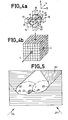
- Figure 1 gives a schematic image of such a segmented volume.
- facets such as 1 of the cubic volume elements of the segmented volume as illuminated and reflective surfaces of a light of illumination.
- This solution which intuitively exhibits great simplicity in processing the illumination signal due to the small number of possible illuminated surfaces, has however a drawback: it is only capable of giving views of an artificial contour, different from the contour real, because the facet normals are estimated with respect to the three Cartesian axes of description of this object (x, y, z).
- Other more effective visualization techniques are possible: they are all based on the same principle.
- the definition of the facets is only more precise, the possibilities of orientation of the facets are not limited, the images of the views presented are less coarse, but they are also longer to calculate.
- the object of the present invention is to remedy these drawbacks by assigning, during the segmentation, to each of the discriminated volume elements a parameter.
- This parameter depends on the exploration mode of the digital volume, and this parameter and this exploration mode are such that a different parameter is assigned to each of the different volume elements of the surface of the segmented object.
- the segmentation operates as follows: the memory cells of the memory are addressed, one after the other, to a comparator which sorts them according to a segmentation criterion.
- the addressing mode of the computer memory is then a mode dependent on the architecture technology of this computer. For example, the addressing of the memory is done cell by cell in a memory line, line by line in a memory plane, and plane after plane in the memory.
- the mode of addressing the memory or, which amounts to the same mode of exploring the corresponding digital volume is not imposed by computer technology. On the contrary, it depends on a specific process. This specific process is particularly linked to the place from the point of view from which one is supposed to visualize the object. Under these conditions, each volume element discriminated against is provided with a parameter, depending on a phase of the exploration mode at the end of which the volume element thus discriminated has been retained. This parameter can then be used to locally modify the segmentation or representation criteria.
- the invention therefore relates to a method of calculating and representing images of views of an object, said object being determined, within a digital volume, by a set volume elements each loaded with at least one piece of physical information, the value of which is representative of this object, process in which - the digital volume is segmented by digital processing on the values of the physical information of the volume elements to discriminate all the volume elements of this object, and in which we visualize an image of a view of this segmented object from '' a given point of view, characterized in that - the segmentation is carried out by assigning to each element of the segmented volume a parameter representative of a mode of exploration of the digital volume.
- FIG. 1 therefore shows in perspective the virtual appearance of a segmented object according to a process in accordance with those known in the state of the art.
- Figure 2 shows a digital volume 2 containing a set volume elements such as 3.
- Some of these volume elements, underlined by an imprecise outline 4, are loaded with physical information whose value is representative of their belonging to a particular object, for example such as bone in FIG. 1.
- the value of the radiological densities of the volume elements circumscribed by the contour 4 is likely to belong to a range of values retained as a criterion for discriminating the volume 4 (FIG. 3a).
- a particular feature of the invention lies in the mode of exploration of the digital volume. Indeed rather than considering the volume elements, or even the corresponding memory cells, in a sequential manner organized according to the three reference axes of this volume, or of this memory, we can on the contrary decide to explore this volume, this memory, by studying the succession of volume elements, memory cells, which are located along a straight line D i . We know how to calculate the equation of such a line D i with respect to a reference x, y, z, linked to the digital volume. It is therefore possible to successively access the volume elements which, for example in the drawing from right to left, are intersected by this right.
- each line D i for exploring the digital volume is parallel to each other. This means that their directing angles M and N are the same for all.
- Each line can then be configured simply by the coordinates x i y i of its point A of meeting with a reference xy plane.
- each point of the image to be displayed can then only be affected by a two-dimensional parameter (x i , y i ) while the image viewed, she, can be assigned two other dimensions of the parameter (M, N,) depending on the mode of observation of the displayed image.
- this type of exploration of the digital volume leads to the representation of axonometric images, that is to say in false perspective.
- FIGS. 3a and 3b show a preferred way of carrying out the segmentation of the object 4.
- the information contained in the volume elements can be sequentially presented to a comparator which determines for which addresses the value of this information is contained within a range of values 5-6.
- the result of this determination may lead to consider that before the address a i we are not in the segmented object, but that afterwards we enter it.
- the exact determination of the address a i can be made difficult by the noisy nature of the physical information signal in the vicinity of the transition between the object 4 and what is external to it as well as by the more or less sharp appearance of this transition itself.
- the volume element of the series of volume elements belonging on the right D i for which this sum is the highest be the volume element selected, i.e. can be considered as belonging to the surface of the object 4 at the point of intersection of the line D i with this object 4.
- the calculation of these gradients is carried out according to a method of the type of those invented by SW ZUCKER ( "A THREE-DIMENSIONAL EDGE OPERATOR” IEEE PAMI, Vol. PAMI-3, No. 3, May 1981, pp 324-331) or DG MORGENTHALER ( "EDGE DETECTION bY MULTIDIMENSIONAL hypersurface FITTING, IEEE PAMI, Vol. PAMI- 3, No. 4, July 1981, pp 482-486).
- This automatic change of segmentation criterion has a drawback, however.
- it is transparent to the observer of the image viewed. This one does not know ultimately that it is the exact criterion which prevailed for each of the regions of the displayed image.
- the image may be clear everywhere, but it may not necessarily correspond in every place to the same definition. Under these conditions, it may be preferable to limit the protocol to the first automatic passage: measurement of the threshold being exceeded first, and calculation of the gradient as soon as an address of a volume element likely to belong to the object 4 has been discriminated against. On the other hand, the possibility of associating with certain parts of the image a modification of the discrimination criterion is reserved.
- this dimension relates to the characteristics of the criterion of discrimination of the segmented object.
- This dimension is also by its nature representative of the mode of exploration of digital volume.
- the whole segmented object was defined according to a fixed cell-line-plane exploration mode and according to a common segmentation criterion. It was impossible to locally modify the discrimination conditions since we did not know in the image viewed at what position in space x, y, z, or at what exact address in the machine belong the volume elements, that one represented and which presented defects.
- the method of the invention could have a drawback due to the particular mode of access to the addresses of the various volume elements to be evaluated, and which belong to the lines D i .
- this addressing mode is not as simple as a natural sequential addressing mode, as can be obtained with a reading of the cell-line-plane memory.
- This drawback is minimal and, on the other hand, the method of the invention saves time as soon as it is envisaged to "rotate" the object viewed in front of an observer who looks at the display screen 21.
- only the useful parts of the digital volume are manipulated during segmentation, since we stop browsing this volume as soon as a satisfactory point of intersection is found. This saves computing time.
- the visualization point of view interferes with the invention as a parameter for determining the segmented object. It is thus possible to limit the segmentation of the digital volume to the part which projects into a particular region of the screen (that is to say, limit it to a generalized cylinder). But we can also limit the segmentation to a totally defined subset with respect to object space. For example, if we know a priori the approximate position of the object, we can limit our to a sphere or a parallelepiped encompassing this object. In the cited state of the art, the object was segmented once and for all, and the point of view of visualization depended only on the operations of representing the segmented object.
- the parts common to the displays oriented at 26 and 27 simply have, from one display to another, their parameters x i y i modified according to an algorithm.
- This algorithm is easy to calculate since we know the locations of the segmented volume elements considered and the equations of the lines D i and D ⁇ i which allow them to be reached from one point of view to the other.
- the visualization of the image itself is advantageously simplified with the method of the invention.
- the theory of the illuminations comprises laws, in particular in a modelization known as of LAMBERT. This theory is described in particular in "FUNDAMENTALS OF INTERACTIVE COMPUTER GRAPHICS" published by FOLEY JD and VAN DAM A. at ADDISON-WESLEY in 1982.
- light coming from a region of space can have three reflected components : so-called ambient light, scattered light, and specularly reflected light.
- the ambient light emitted by a facet does not depend on the orientation of this facet. In an image this component intervenes a little like a continuous component of brightness of the whole image.
- the light scattered by a facet is light emitted equally in all directions by this facet. Its intensity, in all these directions, depends on the angle of incidence of the light which illuminated the facet. Specularly reflected light roughly obeys a mirror-like law of reflection. Simply a light ray of illumination is not reflected in a single ray but rather in a cone whose opening angle depends on the specular nature of the material of the facet. For the last two components, we must therefore know the orientation of the facets of the segmented object to perform the representations of the images of the views.
- each surface element 31 of this image is assigned the calculated luminosity of the facet corresponding to the segmented volume element which has been discriminated on the line D i configured. by x i and y i , x i and y i being correlated to X i and Y i .
- Another advantage of the invention is also to give direct access to the volume elements of the surface of the segmented volume.
- an element of volume belongs to object 4 as soon as the value of its physical information is greater than a threshold 5 (neglecting the value 6), we obtain all of the elements of volume belonging to the object 4: the surface of this object 4 is not obtained. It is therefore necessary to carry out the subsequent calculation of this surface by elimination of the elements of volume contained in the object.
- the exploration mode is a directed mode
- the parameter characterizing the exploratory mode of the digital volume can still correspond to something else. Indeed, it is necessary to eliminate the small particles of noise which obstruct the passage of the rays of exploration. We can try to base our on the perimeter of these particles. That is to say, one can try to see which neighboring volume elements have the same characteristics as a discriminated volume element. Step by step, we can either return quickly to the starting point, we revolve around the noise particle, or move away from the discriminated volume element. In the first case, we are in the presence of a noise, we must continue the exploration on the other side of the particle; in the second case we ended up on the surface of the segmented object. In this way, we simply give a spatial coherence to the surface of this object.
Landscapes
- Physics & Mathematics (AREA)
- Engineering & Computer Science (AREA)
- Computer Graphics (AREA)
- Geometry (AREA)
- Software Systems (AREA)
- General Physics & Mathematics (AREA)
- Theoretical Computer Science (AREA)
- Image Analysis (AREA)
- Image Processing (AREA)
- Analysing Materials By The Use Of Radiation (AREA)
- Apparatus For Radiation Diagnosis (AREA)
- Magnetic Resonance Imaging Apparatus (AREA)
Applications Claiming Priority (2)
| Application Number | Priority Date | Filing Date | Title |
|---|---|---|---|
| FR8704728A FR2613509B1 (fr) | 1987-04-03 | 1987-04-03 | Procede de calcul et de representation d'images de vues d'un objet |
| FR8704728 | 1987-04-03 |
Publications (2)
| Publication Number | Publication Date |
|---|---|
| EP0287409A1 true EP0287409A1 (de) | 1988-10-19 |
| EP0287409B1 EP0287409B1 (de) | 1992-06-17 |
Family
ID=9349778
Family Applications (1)
| Application Number | Title | Priority Date | Filing Date |
|---|---|---|---|
| EP88400600A Expired - Lifetime EP0287409B1 (de) | 1987-04-03 | 1988-03-15 | Verfahren zum Berechnen und zur Wiedergabe von Sichtbildern eines Objektes |
Country Status (5)
| Country | Link |
|---|---|
| US (1) | US5095521A (de) |
| EP (1) | EP0287409B1 (de) |
| JP (1) | JPS63266583A (de) |
| DE (1) | DE3872031T2 (de) |
| FR (1) | FR2613509B1 (de) |
Cited By (1)
| Publication number | Priority date | Publication date | Assignee | Title |
|---|---|---|---|---|
| EP0366387A3 (de) * | 1988-10-24 | 1992-03-25 | General Electric Company | Dreidimensionale Bildergewinnung von tomographischen Daten |
Families Citing this family (30)
| Publication number | Priority date | Publication date | Assignee | Title |
|---|---|---|---|---|
| FR2614163B1 (fr) * | 1987-04-17 | 1989-06-09 | Thomson Cgr | Procede de representation d'images de vues d'un objet |
| IL102289A (en) * | 1992-06-24 | 1997-08-14 | R Technologies Ltd B V | Method and system for processing moving images |
| US5490239A (en) * | 1992-10-01 | 1996-02-06 | University Corporation For Atmospheric Research | Virtual reality imaging system |
| US5751289A (en) * | 1992-10-01 | 1998-05-12 | University Corporation For Atmospheric Research | Virtual reality imaging system with image replay |
| US5432895A (en) * | 1992-10-01 | 1995-07-11 | University Corporation For Atmospheric Research | Virtual reality imaging system |
| FR2700909B1 (fr) * | 1993-01-27 | 1995-03-17 | Gen Electric Cgr | Dispositif et procédé automatique de calibration géométrique d'un système d'imagerie par rayons X. |
| DE69426541T2 (de) * | 1993-03-12 | 2001-06-13 | Kabushiki Kaisha Toshiba, Kawasaki | Dokumentdetektionssystem mit Darstellung des Detektionsresultats zur Erleichterung des Verständnis des Benutzers |
| JPH07271594A (ja) * | 1994-03-31 | 1995-10-20 | Mitsubishi Electric Corp | ファジー開発支援装置 |
| WO1998000811A1 (en) * | 1996-06-28 | 1998-01-08 | Resolution Technologies, Inc. | Fly-through computer aided design method and apparatus |
| US6331116B1 (en) | 1996-09-16 | 2001-12-18 | The Research Foundation Of State University Of New York | System and method for performing a three-dimensional virtual segmentation and examination |
| US7194117B2 (en) * | 1999-06-29 | 2007-03-20 | The Research Foundation Of State University Of New York | System and method for performing a three-dimensional virtual examination of objects, such as internal organs |
| US6343936B1 (en) | 1996-09-16 | 2002-02-05 | The Research Foundation Of State University Of New York | System and method for performing a three-dimensional virtual examination, navigation and visualization |
| US7486811B2 (en) * | 1996-09-16 | 2009-02-03 | The Research Foundation Of State University Of New York | System and method for performing a three-dimensional virtual examination of objects, such as internal organs |
| AU2001268217A1 (en) * | 2000-06-06 | 2001-12-17 | The Research Foundation Of State University Of New York | Computer aided visualization, fusion and treatment planning |
| AU2001296506A1 (en) | 2000-10-02 | 2002-04-15 | The Research Foundation Of State University Of New York | Centerline and tree branch skeleton determination for virtual objects |
| US7630750B2 (en) * | 2001-02-05 | 2009-12-08 | The Research Foundation For The State University Of New York | Computer aided treatment planning |
| US7596256B1 (en) | 2001-09-14 | 2009-09-29 | The Research Foundation For The State University Of New York | Computer assisted detection of lesions in volumetric medical images |
| US7324104B1 (en) | 2001-09-14 | 2008-01-29 | The Research Foundation Of State University Of New York | Method of centerline generation in virtual objects |
| US7260250B2 (en) * | 2002-09-30 | 2007-08-21 | The United States Of America As Represented By The Secretary Of The Department Of Health And Human Services | Computer-aided classification of anomalies in anatomical structures |
| US7733298B2 (en) * | 2004-10-19 | 2010-06-08 | Hewlett-Packard Development Company, L.P. | Display device |
| US8452061B2 (en) * | 2005-11-30 | 2013-05-28 | The Research Foundation Of State University Of New York | Electronic colon cleansing method for virtual colonoscopy |
| US20100260390A1 (en) * | 2005-11-30 | 2010-10-14 | The Research Foundation Of State University Of New York | System and method for reduction of false positives during computer aided polyp detection |
| JP4614001B2 (ja) * | 2006-04-13 | 2011-01-19 | 株式会社島津製作所 | 透過x線を用いた三次元定量方法 |
| US7940970B2 (en) * | 2006-10-25 | 2011-05-10 | Rcadia Medical Imaging, Ltd | Method and system for automatic quality control used in computerized analysis of CT angiography |
| US7940977B2 (en) | 2006-10-25 | 2011-05-10 | Rcadia Medical Imaging Ltd. | Method and system for automatic analysis of blood vessel structures to identify calcium or soft plaque pathologies |
| US7983459B2 (en) | 2006-10-25 | 2011-07-19 | Rcadia Medical Imaging Ltd. | Creating a blood vessel tree from imaging data |
| US7873194B2 (en) * | 2006-10-25 | 2011-01-18 | Rcadia Medical Imaging Ltd. | Method and system for automatic analysis of blood vessel structures and pathologies in support of a triple rule-out procedure |
| US7860283B2 (en) | 2006-10-25 | 2010-12-28 | Rcadia Medical Imaging Ltd. | Method and system for the presentation of blood vessel structures and identified pathologies |
| US7853061B2 (en) * | 2007-04-26 | 2010-12-14 | General Electric Company | System and method to improve visibility of an object in an imaged subject |
| JP6026357B2 (ja) | 2013-06-13 | 2016-11-16 | 富士フイルム株式会社 | 仮想内視鏡画像生成装置および方法並びにプログラム |
Family Cites Families (11)
| Publication number | Priority date | Publication date | Assignee | Title |
|---|---|---|---|---|
| US3621214A (en) * | 1968-11-13 | 1971-11-16 | Gordon W Romney | Electronically generated perspective images |
| US3602702A (en) * | 1969-05-19 | 1971-08-31 | Univ Utah | Electronically generated perspective images |
| US4710876A (en) * | 1985-06-05 | 1987-12-01 | General Electric Company | System and method for the display of surface structures contained within the interior region of a solid body |
| US4729098A (en) * | 1985-06-05 | 1988-03-01 | General Electric Company | System and method employing nonlinear interpolation for the display of surface structures contained within the interior region of a solid body |
| US4952922A (en) * | 1985-07-18 | 1990-08-28 | Hughes Aircraft Company | Predictive look ahead memory management for computer image generation in simulators |
| US4719585A (en) * | 1985-08-28 | 1988-01-12 | General Electric Company | Dividing cubes system and method for the display of surface structures contained within the interior region of a solid body |
| US4835712A (en) * | 1986-04-14 | 1989-05-30 | Pixar | Methods and apparatus for imaging volume data with shading |
| US4751643A (en) * | 1986-08-04 | 1988-06-14 | General Electric Company | Method and apparatus for determining connected substructures within a body |
| US4791567A (en) * | 1986-09-15 | 1988-12-13 | General Electric Company | Three dimensional connectivity system employing an equivalence schema for determining connected substructures within a body |
| US4821213A (en) * | 1986-12-19 | 1989-04-11 | General Electric Co. | System for the simultaneous display of two or more internal surfaces within a solid object |
| US4821210A (en) * | 1987-04-02 | 1989-04-11 | General Electric Co. | Fast display of three-dimensional images |
-
1987
- 1987-04-03 FR FR8704728A patent/FR2613509B1/fr not_active Expired
-
1988
- 1988-03-15 EP EP88400600A patent/EP0287409B1/de not_active Expired - Lifetime
- 1988-03-15 DE DE8888400600T patent/DE3872031T2/de not_active Expired - Lifetime
- 1988-04-04 JP JP63082845A patent/JPS63266583A/ja active Pending
-
1990
- 1990-02-27 US US07/488,458 patent/US5095521A/en not_active Expired - Lifetime
Non-Patent Citations (2)
| Title |
|---|
| ANGEWANDTE INFORMATIK/APPLIED INFORMATICS, vol. 28, no. 4, avril 1986, pages 151-156, Friedr. Vieweg & Sohn Verlagsgesellschaft mbH, Braunschweig, DE; H. MÜLLER: "Erzeugung realistisch wirkender Computergrafik aus komplexen Szenen durch Strahlverfolgung" * |
| IEEE TRANSACTIONS ON MEDICAL IMAGING, vol. MI-5, no. 1, mars 1986, pages 45-47, IEEE, New York, US; K.H. HÖHNE et al.: "Shading 3D-images from CT using gray-level gradients" * |
Cited By (1)
| Publication number | Priority date | Publication date | Assignee | Title |
|---|---|---|---|---|
| EP0366387A3 (de) * | 1988-10-24 | 1992-03-25 | General Electric Company | Dreidimensionale Bildergewinnung von tomographischen Daten |
Also Published As
| Publication number | Publication date |
|---|---|
| DE3872031D1 (de) | 1992-07-23 |
| FR2613509A1 (fr) | 1988-10-07 |
| DE3872031T2 (de) | 1992-12-03 |
| EP0287409B1 (de) | 1992-06-17 |
| FR2613509B1 (fr) | 1989-06-09 |
| JPS63266583A (ja) | 1988-11-02 |
| US5095521A (en) | 1992-03-10 |
Similar Documents
| Publication | Publication Date | Title |
|---|---|---|
| EP0287409B1 (de) | Verfahren zum Berechnen und zur Wiedergabe von Sichtbildern eines Objektes | |
| EP0379399B1 (de) | Verfahren zum Rechnen und zur Auswertung der kegelförmigen Bildprojektion, z.B. eines Röntgenbildes, eines dreidimensionalen, abgetasteten Objektes und Verfahren zur dreidimensionalen Rekonstruktion eines diesem Rechenverfahren unterliegenden Objektes | |
| Lensch et al. | Image-based reconstruction of spatial appearance and geometric detail | |
| JP4335588B2 (ja) | 3dオブジェクトをモデル化する方法 | |
| EP0927405B1 (de) | Elektronisches bildverarbeitungsgerät zur detektion von dimensionnellen änderungen | |
| Müller et al. | Rapid Synchronous Acquisition of Geometry and Appearance of Cultural Heritage Artefacts. | |
| Haber et al. | Relighting objects from image collections | |
| US6831641B2 (en) | Modeling and rendering of surface reflectance fields of 3D objects | |
| EP3401878B1 (de) | Lichtpfadfusion zum rendering von oberflächen- und volumendaten in der medizinischen bildgebung | |
| FR2902218A1 (fr) | Procede de traitement d'images de tomosynthese pour une detection de signes radiologiques | |
| EP1844438A1 (de) | Verfahren und system zur simulation oder digitalen synthese echographischer bilder | |
| JP2000126173A (ja) | 円錐ビ―ムデ―タのための画像再構築 | |
| Gu et al. | Fast non-line-of-sight imaging with non-planar relay surfaces | |
| JP4335589B2 (ja) | 3dオブジェクトをモデル化する方法 | |
| FR2909207A1 (fr) | Procede de visualisation tridimensionnelle d'images de tomosynthese en mammographie. | |
| EP0368718B1 (de) | Verfahren zur Auswahl eines Objektes in einem n-dimensionalen Referenzsystem und Anzeige des ausgewählten Objektes | |
| Jaffey et al. | Digital reconstruction methods for three-dimensional image visualization | |
| EP0445173B1 (de) | Verfahren zum anzeigen eines in octree eingeteilten objektes | |
| Blasco et al. | Non-Uniform Spherical Light Fields | |
| Jönsson | Enhancing salient features in volumetric data using illumination and transfer functions | |
| Li et al. | Volumetric reconstruction and visualization in three dimensional echocardiography: in vitro investigation | |
| Dachille | Architectures for Realistic Volume Imaging | |
| Dillon et al. | Imaging with Rays: Microscopy, Medical Imaging, and Computer Vision | |
| Zámečník | Interactive preview renderer for complex camera models | |
| Sharifi | Enhancing visual perception in interactive direct volume rendering of medical images |
Legal Events
| Date | Code | Title | Description |
|---|---|---|---|
| PUAI | Public reference made under article 153(3) epc to a published international application that has entered the european phase |
Free format text: ORIGINAL CODE: 0009012 |
|
| AK | Designated contracting states |
Kind code of ref document: A1 Designated state(s): DE GB NL |
|
| 17P | Request for examination filed |
Effective date: 19881121 |
|
| 17Q | First examination report despatched |
Effective date: 19900731 |
|
| RAP1 | Party data changed (applicant data changed or rights of an application transferred) |
Owner name: GENERAL ELECTRIC CGR S.A. |
|
| GRAA | (expected) grant |
Free format text: ORIGINAL CODE: 0009210 |
|
| AK | Designated contracting states |
Kind code of ref document: B1 Designated state(s): DE GB NL |
|
| GBT | Gb: translation of ep patent filed (gb section 77(6)(a)/1977) | ||
| REF | Corresponds to: |
Ref document number: 3872031 Country of ref document: DE Date of ref document: 19920723 |
|
| PGFP | Annual fee paid to national office [announced via postgrant information from national office to epo] |
Ref country code: GB Payment date: 19930215 Year of fee payment: 6 |
|
| PGFP | Annual fee paid to national office [announced via postgrant information from national office to epo] |
Ref country code: NL Payment date: 19930331 Year of fee payment: 6 |
|
| PLBE | No opposition filed within time limit |
Free format text: ORIGINAL CODE: 0009261 |
|
| STAA | Information on the status of an ep patent application or granted ep patent |
Free format text: STATUS: NO OPPOSITION FILED WITHIN TIME LIMIT |
|
| 26N | No opposition filed | ||
| PG25 | Lapsed in a contracting state [announced via postgrant information from national office to epo] |
Ref country code: NL Effective date: 19931001 |
|
| NLV4 | Nl: lapsed or anulled due to non-payment of the annual fee | ||
| PG25 | Lapsed in a contracting state [announced via postgrant information from national office to epo] |
Ref country code: GB Effective date: 19940315 |
|
| GBPC | Gb: european patent ceased through non-payment of renewal fee |
Effective date: 19940315 |
|
| PGFP | Annual fee paid to national office [announced via postgrant information from national office to epo] |
Ref country code: DE Payment date: 20050502 Year of fee payment: 18 |
|
| PG25 | Lapsed in a contracting state [announced via postgrant information from national office to epo] |
Ref country code: DE Free format text: LAPSE BECAUSE OF NON-PAYMENT OF DUE FEES Effective date: 20061003 |