EP0287697A1 - Appareil et méthode pour réaliser l'orientation d'un câble coaxial ayant une barre terminale de masse - Google Patents
Appareil et méthode pour réaliser l'orientation d'un câble coaxial ayant une barre terminale de masse Download PDFInfo
- Publication number
- EP0287697A1 EP0287697A1 EP87105994A EP87105994A EP0287697A1 EP 0287697 A1 EP0287697 A1 EP 0287697A1 EP 87105994 A EP87105994 A EP 87105994A EP 87105994 A EP87105994 A EP 87105994A EP 0287697 A1 EP0287697 A1 EP 0287697A1
- Authority
- EP
- European Patent Office
- Prior art keywords
- orientation bar
- connector
- insulation displacement
- coax
- bar means
- Prior art date
- Legal status (The legal status is an assumption and is not a legal conclusion. Google has not performed a legal analysis and makes no representation as to the accuracy of the status listed.)
- Withdrawn
Links
Images


Classifications
-
- H—ELECTRICITY
- H01—ELECTRIC ELEMENTS
- H01R—ELECTRICALLY-CONDUCTIVE CONNECTIONS; STRUCTURAL ASSOCIATIONS OF A PLURALITY OF MUTUALLY-INSULATED ELECTRICAL CONNECTING ELEMENTS; COUPLING DEVICES; CURRENT COLLECTORS
- H01R9/00—Structural associations of a plurality of mutually-insulated electrical connecting elements, e.g. terminal strips or terminal blocks; Terminals or binding posts mounted upon a base or in a case; Bases therefor
- H01R9/03—Connectors arranged to contact a plurality of the conductors of a multiconductor cable, e.g. tapping connections
- H01R9/05—Connectors arranged to contact a plurality of the conductors of a multiconductor cable, e.g. tapping connections for coaxial cables
- H01R9/053—Connectors arranged to contact a plurality of the conductors of a multiconductor cable, e.g. tapping connections for coaxial cables using contact members penetrating insulation
-
- H—ELECTRICITY
- H01—ELECTRIC ELEMENTS
- H01R—ELECTRICALLY-CONDUCTIVE CONNECTIONS; STRUCTURAL ASSOCIATIONS OF A PLURALITY OF MUTUALLY-INSULATED ELECTRICAL CONNECTING ELEMENTS; COUPLING DEVICES; CURRENT COLLECTORS
- H01R9/00—Structural associations of a plurality of mutually-insulated electrical connecting elements, e.g. terminal strips or terminal blocks; Terminals or binding posts mounted upon a base or in a case; Bases therefor
- H01R9/03—Connectors arranged to contact a plurality of the conductors of a multiconductor cable, e.g. tapping connections
- H01R9/05—Connectors arranged to contact a plurality of the conductors of a multiconductor cable, e.g. tapping connections for coaxial cables
Definitions
- This invention relates to an electrical connector, and more particularly, to an electrical connector of the insulation displacement connector-type and a method for connecting a plurality of coax cables to a predetermined contact of the electrical connector and provided a common ground termination in conjunction therewith.
- insulation displacement connectors which are used to produce a cable harness whereby a wire having some dielectric covering (insulation) is forcibly inserted into a contact, the contact being structured to pierce or cut through the insulation and to make contact with the metal conductor (i.e., wire) thereby eliminating the step of stripping the insulation from the wire before making the electrical connection of the wire to the contact.
- the insulation displacement connector (IDC) contact has been developed such that a highly reliable electrical connection is made and has proved to be a highly efficient technique for connecting ribbon cables. No other connections are required when wires of the type mentioned above are used in conjunction with the insulation displacement connector.
- an additional connection must be made; namely, the drain wire (i.e., ground shield and/or the ground wire) must also be connected to a common electrical terminal.
- coaxial ribbon cable consisting of individual coaxial cables encased in a PVC jacket making up a standard flat ribbon cable configuration.
- Each coaxial lead has a solid center conductor (wire) and a foil shield with a drain wire. This construction allows the cable to be cut in any length maintaining the exact positioning of the center conductor (wire) and drain wire.
- the ground termination block allows all of the contacts of the connector to be utilized for the signal conductors of the coax cable, and also provides for using individual coax cables, rather then ribbon cable, for the cable harness.
- Existing ribbon cable drain wires are in between signal conductors and dieletric materials limiting the size of the diameter of the dielectric, thereby limiting higher range of characteristic impedances of the coax.
- An orientation bar of the present invention aligns the drain wires to allow for maximum dielectric diameters, thereby maximizing the higher characteristic impedance range of the coax cable.
- the diameter of the drain wire must be the same or nearly the same as the wire since the contacts on the IDC are the same physical size. In the present invention, since the contacts of the connector are not utilized to terminate the drain wires, no such requirement exists.
- the present invention permits the use of coax cables with the readily available and relatively inexpensive IDC connectors by providing a ground termination bar for making the common ground termination, while still maintaining a relatively simple method of making the connection of the wire and the drain wire.
- the use of the ground termination bar also allows all the contacts of the connector to be available for signal conductors (wires).
- a connector for providing electrical connections for a coax cable harness including a plurality of coax cables, each coax cable having a wire encased in a dielectric and having a drain wire.
- the connector comprises an insulation displacement connector having a plurality of insulation displacement contacts set in a top surface of the insulation displacement connector. Each insulation displacement contact engages a corresponding wire encased in the dielectric, the insulation displacement contact piercing the dielectric thereby providing the electrical connection for the wire of the coax cable.
- An orientation bar positions the coax cables to be in line with the corresponding insulation displacement contact, the coax cables resting on a top surface of the orientation bar.
- the orientation bar is positioned next to the insulation displacement connector such that a side surface of the insulation displacement connector is in contact or nearly in contact with the orientation bar.
- the orientation bar further has a plurality of holes from the top surface which extend to a bottom surface of the orientation bar, each hole being positioned under the corresponding coax cable in order to permit the corresponding drain wire of the coax cable to be inserted through the hole with the end portion of drain wire bent across the bottom surface of the orientation bar.
- a ground termination block having a top surface placed opposite the bottom surface of the orientation bar and fixed against the drain wires bent across the bottom surface of the orientation bar, causes the drain wires to be in pressure contact between the ground termination block and the orientation bar, wherein at least one of the ground termination block or the orientation bar is made of an electrically conducting material.
- the present invention also includes a method of connecting a coax cable harness to a connector, the coax cable harness including a plurality of coax cables, each coax cable having a wire encased in a dielectric and having a drain wire, and each coax cable having been stripped of an outer jacket and accompanying shield.
- the connector includes an insulation displacement connector having insulation displacement contacts, and an orientation bar positioned next to the insulation displacement connector.
- the orientation bar has holes along the length of the orientation bar for each coax cable position opposite each insulation displacement contact.
- each drain wire of the coax cable is bent at about right angles to the length of the coax cable at the point where the outer jacket has been stripped.
- the method comprises the steps of inserting the drain wire in a first hole of the orientation bar such that the coax cable is resting essentially on a top surface of the orientation bar, bending the end portion of the drain wire, which extends from outside the hole at the bottom surface of the orientation bar, parallel to the coax cable, and forcibly inserting the wire encased in the dielectric in the corresponding insulation displacement contact. These steps are repeated for the next adjacent coax cable until all the coax cables have been connected to the corresponding insulation displacement contact.
- a ground termination block is placed along the bottom surface of the orientation bar such that the drain wires are between the orientation bar and the ground termination block. The ground termination block is then fastened to the orientation bar such that the drain wires are held in pressure contact with the ground termination block.
- Figure 1A shows a cut-away isometric view of a coax cable as utilized in conjunction with an electrical connector (or more simply referred to herein as a connector) of the present invention
- Figure 1B shows a cross-sectional view of the coax cable.
- the coax cable 10 consists of a wire 18 (also referred to herein as a metal conductor, and a signal conductor), having a dielectric covering 19 (also referred to herein as insulation).
- a metallic foil 14 Surrounding the insulation 19 is a metallic foil 14 (which can also be a braided wire or other type of metallic substance) for providing a shield for the wire 18.
- a drain wire 16 which makes electrical contact with the metallic foil 14.
- the metallic foil 14 is then encased in an outer jacket 12 of some insulation material.
- the connector 20 of the preferred embodiment of the present invention includes an insulation displacement connector (IDC) 22 which is readily available from connector manufacturers, such as AMP.
- IDC 22 as shown, has two rows of contacts 23 ⁇ and 23 ⁇ , also referred to herein as a front row (or first row) 23 ⁇ , and a back row (or second row) 23 ⁇ .
- the contacts 23 are set in the IDC 22 such that the contacts 23 have an extension embedded into the body of the IDC 22 and protrude from another surface for making contact with a backplane or printed circuit board (not shown since it has no bearing on the present invention).
- the part of the contacts 23 shown extending above a top surface 21 of the IDC 22 include that portion for connecting the coax cable 10 to the contact 23. It is this part of the contact 23 which will be discussed.
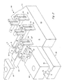
- Included as part of the connector 20 is an orientation bar 26 and a ground termination block 24.
- Coax cables 10 have been stripped of some of the outer jacket 12 and metallic foil 14 such that a predetermined length of the insulation 19 containing wire 18, and drain wire 16 are exposed.
- the stripping can be accomplished through the use of stripping and terminating equipment well known to those skilled in the art; the stripping process will not be discussed further herein since it forms no part of the present invention.
- the insulation 19 and the wire 18 have been stripped the predetermined length such that the length extends beyond the front surface 29 of the IDC 22, the length extension not shown for clarity, but will be discussed further hereinunder.
- the drain wire 16 of each coax cable 10 is bent at approximately 90° to the length of the coax cable such that the drain wire 16 can be inserted into a corresponding hole 25 in the orientation bar 26.
- the orientation bar 26 contains a plurality of slots 27 such that each coax cable 10 fits within the slot 27.
- the drain wire 16 is then wrapped around the bottom of the orientation bar such that the drain wire 16 goes across a W-shaped indentation 30 which is cut into the bottom surface of the orientation bar 26 and extends the entire length of the orientation bar 26.
- the slot 27 of the orientation bar serves to position and orient each coax cable 10 such that the drain wire 16 is facing downward, and positions and holds the coax cable 10 in line with the corresponding contact 23.
- the insulation 19 and wire 18 extends across or slightly above the top surface of the IDC 22 and is inserted into the corresponding contact 23 such that alternate coax cables 10 are connected to contacts 23 within the same row.
- the insulation 19 and wire 18 of coax cable 10-1, 10-3, 10-5 (not shown) ... are connected to corresponding contacts 23 ⁇ in the back row.
- coax cable 10-2, 10-4 (not shown) ... are connected to the corresponding front row contacts 23 ⁇ .
- a top bar 28 is set across the coax cables 10 and the ground termination block 24 is set across the bottom of the orientation bar 26 and fastened together thereby holding the coax cables 10 in position.
- the orientation bar 26 is made of a molded plastic and the ground termination block 24 is made of a metallic substance.
- the ground termination block 24 has a W-shaped protrusion 31 which corresponds to the indentation 30 and lines up with the indentation 30 of the orientation bar 26.
- a step 32 is provided at the two ends of the orientation bar 26 on the surface which mates with the ground termination bar 24 such that a space is provided for the drain wires. It is desirable that the drain wires only be pierced by the protrusion 31 of the ground termination bar 24, thereby avoiding a shearing of the drain wire 16. Such a shearing action could cut the drain wire 16 and thus make an unreliable contact of the drain wire 16 to the ground termination block 24.
- Figure 3A shows a top view of the orientation bar 26 in position with IDC connector 22 at the start of the assembly process.
- Figure 3B shows section A-A of Figure 3A with the connector 20 partially assembled.
- Figure 3C shows section A-A of the completed connector 20.
- a plurality of coax cables 10 are stripped such that a predetermined amount of the outer jacket 12 and metallic foil 14 are removed leaving a predetermined length of the drain wire 16 and a predetermined length of the insulation 19 containing wire 18.
- the length of the drain wire 16 is sufficiently long to fit through hole 25 and bend across the indentation 30 of the orientation bar 26.
- the insulation 19 containing wire 18 is sufficiently long to be inserted into a corresponding contact 23 and extend beyond the IDC connector allowing an assembler to make the proper insertion of the insulation 19 into the corresponding connector 23.
- the orientation bar 26 and IDC connector 22 are mounted into a fixture 50.
- a second fixture 50 also contains a second IDC connector 22 (not shown) and a second orientation bar 26 ⁇ (not shown) for the opposite end of the cable harness.
- a first coax cable 10 having been previously stripped the predetermined lengths at both ends has the drain wire 16 inserted into the first hole 25 of the orientation bar 26 and the remainder of the coax cable 10 inserted into the corresponding slot 27, the insulation 19 containing the wire 18 being inserted into the corresponding contact 23.
- the other end of the first coax cable 10 is likewise inserted into the corresponding first position of the second orientation bar 26 ⁇ (not shown) in a like manner as described above.
- the individual coax cable 10 has been inserted into the first position of the two connectors 20 at both ends of the cable.
- a second coax cable is then inserted into the second position of the first connector 20.
- the assembler continues the process until all the available positions have a coax cable 10 (or all the positions as previously determined, in the preferred embodiment 30 positions exist and hence there are 30 coax cables 10 making up the coax cable harness). After the assembler has inserted the 30th coax cable 10 there should be no available positions in the connectors 20 at both ends of the cable harness.
- the top bar 28 is placed on the top surface of the orientation bar 26 and across the coax cables 10.
- the ground termination block 24 is placed under the orientation bar 26, and the top bar 28, the orientation bar 26, and the ground termination block 24 are fastened together.
- the connector 20 can then be removed from the fixture 50 and the insulation 19 containing the wires 18 and the drain wires 16 are then trimmed flush with the surface of the IDC connector 22 and the orientation bar 26, respectively.
- a simple visual inspection of the connectors at both ends would verify that all the positions are occupied thereby eliminating the electrical check, commonly known as "ringing-out" the cable can be eliminated.
- a dielectric covering 51 can be placed over the contacts 23 to further install the drain wires 16 into the contacts 23 and also to avoid any physical damage to the contacts 23.
- a cable harness can be made embodying the present invention which includes a second plane of coax cables 10-101.
- a second orientation bar 26 ⁇ having notches 27 ⁇ are positioned such that the drain wire 16 of the coax cable 10-101 is inserted into hole 25 ⁇ of the second orientation bar 26 ⁇ and made to be oriented opposite a corresponding hole 29 in the orientation bar 26.
- the drain wire 16 of coax cable 10-101 passes between coax cables 10-1 and 10-2. Additional coax cables 10-102, 10-103, (not shown) ...
- the contact 23′′′ which is utilized to make the connection of the wire 18 corresponding to coax cable 10-101, can be on a pedestal 36 of the IDC connector 22, or the contact 23′′′ may be sufficiently high to engage the insulation 19 and corresponding wire 18 of coax cable 10-101 without interfering with the connections made by the contacts of the first and second row, 23 ⁇ , 23 ⁇ .
- the spacing between contacts 23 in the first row and the second row is sufficiently far apart, or the diameter of the coax cables 10 is sufficiently small, such that there is sufficient space for the drain wires 16 of coax cable 10-101 to fit between adjacent coax cables 10 (i.e., coax cables 10-1 and 10-2).
- FIG. 5 there is shown still another alternative embodiment of the present invention.
- the orientation bar 26 is shown made of an electrically conducting material (i.e., a metallic substance) which is positioned next to the IDC connector 22 such that the insulation 19 containing the wire 18 of the coax cable 10 is positioned to a corresponding IDC contact 23.
- the drain wire 16 is positioned along a side surface of IDC connector 22 and a side surface of the orientation bar 26 with the coax cable 10 resting along the top surface of the orientation bar 26.
- holes are provided for fastening IDC connector 22 to orientation bar 26 such that pressure is exerted against the drain wire 16.
- the fastening can be accomplished by a fastener 52.
- all the drain wires 16 are making physical contact with orientation bar 26.
- This arrangement holds drain wires 16 in place as a result of the pressure between the orientation bar 26 and the IDC connector 22, and also serves to hold the coax cables 10 in position.
- Such an arrangement may be suitable when little or no stress is placed upon the coax cables 10.
- a top bar 28 (not shown) may be placed across the top surfaces of the coax cable 10 and fastened to orientation bar 26 as done in the preferred embodiment described above.
- a dielectric covering (not shown) can be placed over the contacts 23 as discussed above in connection with the preferred embodiment.
Landscapes
- Multi-Conductor Connections (AREA)
Priority Applications (2)
| Application Number | Priority Date | Filing Date | Title |
|---|---|---|---|
| US06/849,085 US4662067A (en) | 1986-04-07 | 1986-04-07 | Apparatus and method for providing orientation of a coax cable having a ground termination bar |
| EP87105994A EP0287697A1 (fr) | 1987-04-24 | 1987-04-24 | Appareil et méthode pour réaliser l'orientation d'un câble coaxial ayant une barre terminale de masse |
Applications Claiming Priority (1)
| Application Number | Priority Date | Filing Date | Title |
|---|---|---|---|
| EP87105994A EP0287697A1 (fr) | 1987-04-24 | 1987-04-24 | Appareil et méthode pour réaliser l'orientation d'un câble coaxial ayant une barre terminale de masse |
Publications (1)
| Publication Number | Publication Date |
|---|---|
| EP0287697A1 true EP0287697A1 (fr) | 1988-10-26 |
Family
ID=8196941
Family Applications (1)
| Application Number | Title | Priority Date | Filing Date |
|---|---|---|---|
| EP87105994A Withdrawn EP0287697A1 (fr) | 1986-04-07 | 1987-04-24 | Appareil et méthode pour réaliser l'orientation d'un câble coaxial ayant une barre terminale de masse |
Country Status (1)
| Country | Link |
|---|---|
| EP (1) | EP0287697A1 (fr) |
Cited By (2)
| Publication number | Priority date | Publication date | Assignee | Title |
|---|---|---|---|---|
| EP0392422A1 (fr) * | 1989-04-14 | 1990-10-17 | Entrelec Sa | Procédé de connexion dérivative et de piquage d'un cable électrique multifilaire blindé et connecteur pour la mise en oeuvre du procédé |
| CN117117457A (zh) * | 2023-09-29 | 2023-11-24 | 长飞光纤光缆股份有限公司 | 引入随机量的同轴电缆生产方法、同轴电缆及装置 |
Citations (3)
| Publication number | Priority date | Publication date | Assignee | Title |
|---|---|---|---|---|
| EP0009337A1 (fr) * | 1978-09-05 | 1980-04-02 | AMP INCORPORATED (a New Jersey corporation) | Méthode pour terminer un câble plat électrique multiconducteur et connecteur approprié |
| US4345811A (en) * | 1980-03-27 | 1982-08-24 | Burroughs Corporation | Flat ribbon cable shield |
| US4365856A (en) * | 1980-07-09 | 1982-12-28 | Hirose Electric Co., Ltd. | Electric connector for coaxial ribbon cable |
-
1987
- 1987-04-24 EP EP87105994A patent/EP0287697A1/fr not_active Withdrawn
Patent Citations (3)
| Publication number | Priority date | Publication date | Assignee | Title |
|---|---|---|---|---|
| EP0009337A1 (fr) * | 1978-09-05 | 1980-04-02 | AMP INCORPORATED (a New Jersey corporation) | Méthode pour terminer un câble plat électrique multiconducteur et connecteur approprié |
| US4345811A (en) * | 1980-03-27 | 1982-08-24 | Burroughs Corporation | Flat ribbon cable shield |
| US4365856A (en) * | 1980-07-09 | 1982-12-28 | Hirose Electric Co., Ltd. | Electric connector for coaxial ribbon cable |
Cited By (4)
| Publication number | Priority date | Publication date | Assignee | Title |
|---|---|---|---|---|
| EP0392422A1 (fr) * | 1989-04-14 | 1990-10-17 | Entrelec Sa | Procédé de connexion dérivative et de piquage d'un cable électrique multifilaire blindé et connecteur pour la mise en oeuvre du procédé |
| FR2646024A1 (fr) * | 1989-04-14 | 1990-10-19 | Entrelec Sa | Connecteur de piquage pour cable electrique blinde |
| CN117117457A (zh) * | 2023-09-29 | 2023-11-24 | 长飞光纤光缆股份有限公司 | 引入随机量的同轴电缆生产方法、同轴电缆及装置 |
| CN117117457B (zh) * | 2023-09-29 | 2024-03-08 | 长飞光纤光缆股份有限公司 | 引入随机量的同轴电缆生产方法、同轴电缆及装置 |
Similar Documents
| Publication | Publication Date | Title |
|---|---|---|
| EP0228750B1 (fr) | Connecteur pour un câble coaxial | |
| US4770645A (en) | Cable conductor to printed wiring board conductor clamp | |
| US4639054A (en) | Cable terminal connector | |
| US4533199A (en) | IDC termination for coaxial cable | |
| US4310208A (en) | Molded electrical connector | |
| EP0080365B1 (fr) | Raccordement d'un câble blindé | |
| US4181384A (en) | Flat cable connector having wire deployment means | |
| US4484791A (en) | Connector for multiconductor flat insulated cable | |
| EP0743707B1 (fr) | Modules connecteur | |
| US5618202A (en) | Connector having strip line structure | |
| JPS63193472A (ja) | 電気コネクタ及びその製造方法 | |
| US4797112A (en) | Wire holders and harnesses incorporating wire holders | |
| JPH0744046B2 (ja) | 絶縁穿孔導電端子 | |
| EP0615306B1 (fr) | Connecteur électrique collectif | |
| US4662067A (en) | Apparatus and method for providing orientation of a coax cable having a ground termination bar | |
| US5281170A (en) | Round-to-flat shielded connector assembly | |
| US20140060929A1 (en) | Surface mount connector for electrically isolating two insulated conductors | |
| US4187606A (en) | Flexible electrical jumper and method of making same | |
| US4342152A (en) | Methods of terminating and connectorizing cables | |
| US20110250797A1 (en) | Cable assembly with improved terminating means | |
| WO1992020121A1 (fr) | Connecteur protege a contact autodenudant et a impedance controlee | |
| EP0282194B1 (fr) | Connecteur pour câble électrique | |
| EP0287697A1 (fr) | Appareil et méthode pour réaliser l'orientation d'un câble coaxial ayant une barre terminale de masse | |
| US5238428A (en) | Round-to-flat shielded connector assembly | |
| US5476388A (en) | Connector block |
Legal Events
| Date | Code | Title | Description |
|---|---|---|---|
| PUAI | Public reference made under article 153(3) epc to a published international application that has entered the european phase |
Free format text: ORIGINAL CODE: 0009012 |
|
| AK | Designated contracting states |
Kind code of ref document: A1 Designated state(s): DE FR GB IT |
|
| 17P | Request for examination filed |
Effective date: 19890419 |
|
| 17Q | First examination report despatched |
Effective date: 19911009 |
|
| STAA | Information on the status of an ep patent application or granted ep patent |
Free format text: STATUS: THE APPLICATION HAS BEEN WITHDRAWN |
|
| 18W | Application withdrawn |
Withdrawal date: 19930113 |
|
| R18W | Application withdrawn (corrected) |
Effective date: 19930113 |
|
| RIN1 | Information on inventor provided before grant (corrected) |
Inventor name: ABRAHAM, RONALD FRANK |