EP0287738A1 - Einrichtung zum Entfetten, Trocknen oder Abgraten von mechanischen Einzelteilen - Google Patents
Einrichtung zum Entfetten, Trocknen oder Abgraten von mechanischen Einzelteilen Download PDFInfo
- Publication number
- EP0287738A1 EP0287738A1 EP87402881A EP87402881A EP0287738A1 EP 0287738 A1 EP0287738 A1 EP 0287738A1 EP 87402881 A EP87402881 A EP 87402881A EP 87402881 A EP87402881 A EP 87402881A EP 0287738 A1 EP0287738 A1 EP 0287738A1
- Authority
- EP
- European Patent Office
- Prior art keywords
- boxes
- box
- machine according
- treatment
- parts
- Prior art date
- Legal status (The legal status is an assumption and is not a legal conclusion. Google has not performed a legal analysis and makes no representation as to the accuracy of the status listed.)
- Withdrawn
Links
- 238000005238 degreasing Methods 0.000 title claims description 7
- 238000001035 drying Methods 0.000 title claims description 6
- 238000007789 sealing Methods 0.000 claims description 4
- 230000000903 blocking effect Effects 0.000 claims description 2
- 238000013519 translation Methods 0.000 abstract description 7
- 238000004140 cleaning Methods 0.000 description 4
- 238000007664 blowing Methods 0.000 description 3
- 238000003971 tillage Methods 0.000 description 3
- 239000007788 liquid Substances 0.000 description 2
- 238000003754 machining Methods 0.000 description 2
- 239000002184 metal Substances 0.000 description 2
- 238000005507 spraying Methods 0.000 description 2
- 238000012546 transfer Methods 0.000 description 2
- 239000011248 coating agent Substances 0.000 description 1
- 238000000576 coating method Methods 0.000 description 1
- 238000013461 design Methods 0.000 description 1
- 238000010438 heat treatment Methods 0.000 description 1
- 238000009434 installation Methods 0.000 description 1
- 238000002955 isolation Methods 0.000 description 1
- 238000012423 maintenance Methods 0.000 description 1
- 238000004519 manufacturing process Methods 0.000 description 1
- 238000000034 method Methods 0.000 description 1
- 238000000465 moulding Methods 0.000 description 1
- 238000012545 processing Methods 0.000 description 1
- 239000007921 spray Substances 0.000 description 1
- 238000005406 washing Methods 0.000 description 1
Images


Classifications
-
- C—CHEMISTRY; METALLURGY
- C23—COATING METALLIC MATERIAL; COATING MATERIAL WITH METALLIC MATERIAL; CHEMICAL SURFACE TREATMENT; DIFFUSION TREATMENT OF METALLIC MATERIAL; COATING BY VACUUM EVAPORATION, BY SPUTTERING, BY ION IMPLANTATION OR BY CHEMICAL VAPOUR DEPOSITION, IN GENERAL; INHIBITING CORROSION OF METALLIC MATERIAL OR INCRUSTATION IN GENERAL
- C23G—CLEANING OR DE-GREASING OF METALLIC MATERIAL BY CHEMICAL METHODS OTHER THAN ELECTROLYSIS
- C23G3/00—Apparatus for cleaning or pickling metallic material
Definitions
- the present invention relates to a machine for degreasing, blowing, drying or deburring various mechanical parts comprising a tool release device and positioning this tool around the part to be treated.
- the treatment boxes are fixed and monobloc. It is therefore necessary to allow effective treatment to move the part to be treated so as to properly position it in the treatment boxes.
- the devices according to the prior art require the installation of a mechanical clamping and movement means of the part, a means which is generally bulky and difficult to introduce into the supply boxes, which reduces the effectiveness of the treatment. .
- GB-A-455810 relates to a method and an apparatus for the internal coating of metal containers.
- Metal boxes are fed on a conveyor and are brought under the nozzles of a projection device.
- the projection device is fixed and not removable.
- FR-A-2120775 describes and illustrates a cleaning device in which there are provided means for spraying cleaning liquid over a tank.
- EP-A-0201746 describes a cleaning device in which a tool support allows tilting of a workpiece by a spray nozzle located below said support.
- the present invention provides a machine for degreasing, drying or deburring various parts in which the tools with their supply boxes move to allow the treatment of the part by enclosing it in the boxes or to facilitate the disassembly of tools by clearing all the boxes from the treatment area.
- the machine according to the present invention consists of several elements that can be modulated with respect to each other and more particularly of a tool release module, a tool translation module and a tool rotation module. .
- Each module can be driven either manually or automatically by an electric, pneumatic or hydraulic drive system.
- the machine according to the present invention provides very significant advantages. These advantages are indicated below:
- the machine can be used as well in the case of spraying a liquid, washing-degreasing, blowing, high pressure deburring.
- the machine avoids moving the part to ensure treatment.
- the machine makes it possible to effectively treat all the faces of the parts thanks to the translation of the tools.
- the machine makes it possible to precisely position the tools relative to the part to be treated.
- the machine translates the part to be treated perpendicular to the axis of translation of the tools.
- the machine allows the release of the tools outside the treatment area.
- the machine seals the treatment area in the working position.
- the machine ensures great accessibility to mechanical elements in the treatment area.
- the machine also allows quick access to tools (injectors or nozzles).
- the present invention therefore provides a machine for degreasing, drying, deburring various mechanical parts comprising a tunnel constituting a treatment zone traversed transversely by a mechanism for conveying the parts to be treated, said mechanism being capable of being moved at will according to all predetermined sequences for bringing the parts to be treated into a plurality of boxes internally provided with tools for the treatment of parts and mounted in series along the conveying mechanism which is characterized in that each box consists of two adaptable boxes arranged in look at each other on either side of the conveying mechanism, said boxes being subject to drive and guide means capable of subjecting them to a translational movement in a direction perpendicular to the routing of the parts in order to nest them around the part to be treated during the working stage and the retract at the desired time after the work step to allow their accessibility outside the treatment tunnel.
- the present invention also relates to the characteristics below considered in isolation or in all their technically possible combinations: - At least one box of a box is further subject to means imparting a rotation capable of rotating it laterally in the retracted position; - the means of driving the boxes consist of at least one cylinder; - The drive means of the boxes are constituted by at least one gear motor; - The guide means are columns passing through ball bushings; - The guide means are constituted by a pinion-rack assembly; - The means imparting rotation to a box in the retracted position outside the treatment tunnel is an orientation ring mounted at the top of a box and cooperating with a rotation blocking cam; - the boxes have an identical shape to form a parallelepiped box; - a plate with seal is provided at the rear of the boxes for sealing the treatment area in the working position; - Each box internally contains a plurality of tools such as projection nozzles.
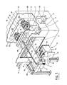
- the machine for degreasing, drying and deburring various mechanical parts 1 comprises a tunnel 2 constituting a treatment area 3.
- a routing mechanism 4 for the parts to be treated 1 moves transversely in the tunnel 2.
- Each box 5 consists of two adaptable boxes 6, 7, 8, 9 arranged opposite each other on either side of the routing mechanism 4. These boxes 6, 7, 8, 9 are subject to drive and guide means capable of subjecting them to a translational movement in a direction perpendicular to the conveying mechanism 4 of the parts to be treated 1 in order to fit them around it during the work step and retract them, at the desired time, after the work step to allow their accessibility outside the treatment tunnel 2.
- the boxes 6, 7, 8, 9 with their tools translate on columns 12 by means of ball bushings 13.
- Each box 6, 7, 8, 9 is driven in translation either by a jack 10 pneumatic or hydraulic either by an electric motor.
- This assembly translates on columns 12 by means of ball bushings 13 and is driven in translation by a geared motor 11 by means of a pinion mechanism 14 rack 15.
- the boxes on each side of the conveying means 4 are provided with a plate with seal 18 ensuring the sealing of the treatment zone 3 in the working position.
- the box 7 with its or fillings (nozzles or injectors 19) is installed under an orientation ring 16 so as to allow its rotation to facilitate access to the tools, the box 7 being locked in rotation by a cam 17.
- the position of the assembly is controlled electrically by a management cabinet not shown.
- This assembly translates on the columns 12 by means of ball bushings 13 and is driven in translation either by a pneumatic or hydraulic jack 10 or by an electric geared motor 11.
- a chassis 20 ensures the establishment and maintenance of the various modules used in the present invention.
- the machine according to the present invention operates in the following manner:
- boxes 6 and 7, 8 and 9 etc ... are brought into position around the part 1 to carry out the treatment. After a certain processing time determined by the management cabinet, the boxes 6 and 7 translate to release the part 1 and allow its transfer. When a tool in any box 6, 7, 8, 9 etc ... is damaged, the operator can either in manual or automatic completely disengage said box 6, 7, 8, 9 etc ... from the area of treatment 3 by means of the geared motor 11, the sealing plate 18 is no longer applied against the treatment zone 3, which allows easy access to the internal mechanism. On another side, when any of the boxes 6, 7, 8, 9 etc ...
- Each box can include, like the box 7, a means of pivoting on itself constituted by an orientation ring 16 to gain access to the tools and an operator can carry out such an operation manually.
- two boxes arranged opposite one another like boxes 6 and 7 fit perfectly one inside the other and in a sealed manner around the part 1 to be treated when one wishes to perform an operation and that in this position it constitutes a box 5.
- each box dissociates into a box and in each box it is possible to carry out outside the treatment zone the desired operation.
- the number of boxes arranged in series can vary at will depending on the number of operations to be performed. Thanks to the possibility offered by the present invention to be able to individually move one of the boxes and no longer have a monobloc box as was the case in the past, a much higher yield is obtained than was previously possible because the machine can operate from uninterrupted way.
Landscapes
- Chemical & Material Sciences (AREA)
- Chemical Kinetics & Catalysis (AREA)
- General Chemical & Material Sciences (AREA)
- Engineering & Computer Science (AREA)
- Materials Engineering (AREA)
- Mechanical Engineering (AREA)
- Metallurgy (AREA)
- Organic Chemistry (AREA)
- Cleaning By Liquid Or Steam (AREA)
- Drying Of Solid Materials (AREA)
- Finish Polishing, Edge Sharpening, And Grinding By Specific Grinding Devices (AREA)
Applications Claiming Priority (2)
| Application Number | Priority Date | Filing Date | Title |
|---|---|---|---|
| FR8617692 | 1986-12-17 | ||
| FR8617692A FR2608471B1 (fr) | 1986-12-17 | 1986-12-17 | Machine pour degraisser, secher, ebavurer des pieces mecaniques diverses |
Publications (1)
| Publication Number | Publication Date |
|---|---|
| EP0287738A1 true EP0287738A1 (de) | 1988-10-26 |
Family
ID=9342013
Family Applications (1)
| Application Number | Title | Priority Date | Filing Date |
|---|---|---|---|
| EP87402881A Withdrawn EP0287738A1 (de) | 1986-12-17 | 1987-12-16 | Einrichtung zum Entfetten, Trocknen oder Abgraten von mechanischen Einzelteilen |
Country Status (4)
| Country | Link |
|---|---|
| EP (1) | EP0287738A1 (de) |
| DE (1) | DE287738T1 (de) |
| ES (1) | ES2004842A4 (de) |
| FR (1) | FR2608471B1 (de) |
Citations (3)
| Publication number | Priority date | Publication date | Assignee | Title |
|---|---|---|---|---|
| GB455810A (en) * | 1935-07-06 | 1936-10-28 | Crosse & Blackwell Ltd | Process and apparatus for the internal coating of metal containers |
| FR2120775A5 (de) * | 1970-12-10 | 1972-08-18 | Nordnero Ab | |
| EP0201746A1 (de) * | 1985-05-02 | 1986-11-20 | Siemens Aktiengesellschaft | Reinigungsvorrichtung für auf Förderbahnen fortbewegte Teile |
-
1986
- 1986-12-17 FR FR8617692A patent/FR2608471B1/fr not_active Expired
-
1987
- 1987-12-16 ES ES87402881T patent/ES2004842A4/es active Pending
- 1987-12-16 EP EP87402881A patent/EP0287738A1/de not_active Withdrawn
- 1987-12-16 DE DE1987402881 patent/DE287738T1/de active Pending
Patent Citations (3)
| Publication number | Priority date | Publication date | Assignee | Title |
|---|---|---|---|---|
| GB455810A (en) * | 1935-07-06 | 1936-10-28 | Crosse & Blackwell Ltd | Process and apparatus for the internal coating of metal containers |
| FR2120775A5 (de) * | 1970-12-10 | 1972-08-18 | Nordnero Ab | |
| EP0201746A1 (de) * | 1985-05-02 | 1986-11-20 | Siemens Aktiengesellschaft | Reinigungsvorrichtung für auf Förderbahnen fortbewegte Teile |
Also Published As
| Publication number | Publication date |
|---|---|
| ES2004842A4 (es) | 1989-02-16 |
| FR2608471B1 (fr) | 1989-05-05 |
| DE287738T1 (de) | 1989-03-30 |
| FR2608471A1 (fr) | 1988-06-24 |
Similar Documents
| Publication | Publication Date | Title |
|---|---|---|
| EP0201395B1 (de) | Einrichtung zum Zusammenbau, insbesondere für Karosseriebearbeitungsstrassen | |
| WO2017050839A1 (fr) | Système de maintenance pour tunnelier et tunnelier associé | |
| EP0274925B1 (de) | Vorrichtung zur Exploration und/oder Behandlung einer ebenen runden Fläche | |
| CH658216A5 (fr) | Procede de finissage de pieces moulees ou usinees et centre de finissage pour la mise en oeuvre de ce procede. | |
| EP0388296B1 (de) | Interventionsvorrichtung, insbesondere zur Prüfung, Inspektion und Wartung von Wärmeaustauschern | |
| WO2018087488A1 (fr) | Dispositif porte-outil pour appareil de fabrication additive selective | |
| EP0500404A1 (de) | Verfahren und Vorrichtung zur Zerlegung interner Komponent eines wassergekühlten Kernreaktors | |
| WO2001056705A1 (fr) | Dispositif de pulverisation destine notamment a une cabine de peinture de carrosserie automobile | |
| EP0465283A1 (de) | Verfahren und Vorrichtung zur Zerlegung eines bestrahlten Komponents eines Kernreaktors durch Bearbeitung seiner Wandung | |
| FR2960227A1 (fr) | Dispositif de support et d'entrainement en rotation de pieces devant subir un traitement de surface et installation mettant en œuvre un tel dispositif | |
| EP0620061B1 (de) | Vorrichtung zum schnellen Wechseln und Halten einer Seitenwand einer Doppelrollenstranggiessvorrichtung beim Giessen eines Metallproduktes | |
| FR2695853A1 (fr) | Machine à fraiser, à surfacer et à polir à changement automatique d'outils et dispositif correspondant. | |
| EP0287738A1 (de) | Einrichtung zum Entfetten, Trocknen oder Abgraten von mechanischen Einzelteilen | |
| FR2701696A1 (fr) | Mécanisme de manutention pour palettes support de pièces. | |
| EP2130614B1 (de) | Behandlungsvorrichtung für Werkteile | |
| EP0452312A1 (de) | Werkzeugmaschine, aus bauteilen zusammengesetzt und mit mindestens einer bearbeitungseinheit | |
| FR2671295A1 (fr) | Robot notamment de lavage. | |
| FR2754483A1 (fr) | Appareil destine a accroitre la resistance mecanique d'une surface d'un element metallique | |
| EP0778103B1 (de) | Verfahren und Vorrichtung zum serienweise elektrochemischen Ätzen von Werstücken | |
| JPH08216100A (ja) | 高圧バリ取り洗浄装置 | |
| EP0696806B1 (de) | Einrichtung zum Positionieren von Kernbrennstabbündeln | |
| EP0494808A1 (de) | Roboter | |
| EP0407537B1 (de) | Maschine und verfahren zum bearbeiten und/oder fertigbearbeiten von gegossenen oder bearbeiteten werkstücken | |
| EP0340104A1 (de) | Vorrichtung zur Eintauchbehandlung eines rohrförmigen Gegenstandes, der eine äussere zerkratzbare Oberfläche aufweisst in einem Becken | |
| FR2744469A1 (fr) | Machine pour la renovation d'ouvrages d'art tubulaires tels que des egouts |
Legal Events
| Date | Code | Title | Description |
|---|---|---|---|
| PUAI | Public reference made under article 153(3) epc to a published international application that has entered the european phase |
Free format text: ORIGINAL CODE: 0009012 |
|
| AK | Designated contracting states |
Kind code of ref document: A1 Designated state(s): AT BE CH DE ES FR GB IT LI LU NL SE |
|
| 17P | Request for examination filed |
Effective date: 19880824 |
|
| TCNL | Nl: translation of patent claims filed | ||
| GBC | Gb: translation of claims filed (gb section 78(7)/1977) | ||
| TCAT | At: translation of patent claims filed | ||
| DET | De: translation of patent claims | ||
| 17Q | First examination report despatched |
Effective date: 19891213 |
|
| STAA | Information on the status of an ep patent application or granted ep patent |
Free format text: STATUS: THE APPLICATION IS DEEMED TO BE WITHDRAWN |
|
| 18D | Application deemed to be withdrawn |
Effective date: 19910817 |