EP0287755A1 - Raccord bout à bout entre deux tubes de tôle mince - Google Patents
Raccord bout à bout entre deux tubes de tôle mince Download PDFInfo
- Publication number
- EP0287755A1 EP0287755A1 EP88101285A EP88101285A EP0287755A1 EP 0287755 A1 EP0287755 A1 EP 0287755A1 EP 88101285 A EP88101285 A EP 88101285A EP 88101285 A EP88101285 A EP 88101285A EP 0287755 A1 EP0287755 A1 EP 0287755A1
- Authority
- EP
- European Patent Office
- Prior art keywords
- ring
- flange
- wall
- butt joint
- rim
- Prior art date
- Legal status (The legal status is an assumption and is not a legal conclusion. Google has not performed a legal analysis and makes no representation as to the accuracy of the status listed.)
- Granted
Links
- 239000002184 metal Substances 0.000 title claims abstract description 5
- 210000001503 joint Anatomy 0.000 claims abstract description 16
- 238000007789 sealing Methods 0.000 claims description 6
- 150000001875 compounds Chemical class 0.000 claims description 4
- 238000005192 partition Methods 0.000 claims 1
- KGNDCEVUMONOKF-UGPLYTSKSA-N benzyl n-[(2r)-1-[(2s,4r)-2-[[(2s)-6-amino-1-(1,3-benzoxazol-2-yl)-1,1-dihydroxyhexan-2-yl]carbamoyl]-4-[(4-methylphenyl)methoxy]pyrrolidin-1-yl]-1-oxo-4-phenylbutan-2-yl]carbamate Chemical compound C1=CC(C)=CC=C1CO[C@H]1CN(C(=O)[C@@H](CCC=2C=CC=CC=2)NC(=O)OCC=2C=CC=CC=2)[C@H](C(=O)N[C@@H](CCCCN)C(O)(O)C=2OC3=CC=CC=C3N=2)C1 KGNDCEVUMONOKF-UGPLYTSKSA-N 0.000 description 2
- 229940125833 compound 23 Drugs 0.000 description 2
- 230000000284 resting effect Effects 0.000 description 2
- 208000036590 Maladministrations Diseases 0.000 description 1
- 239000011324 bead Substances 0.000 description 1
- 238000010276 construction Methods 0.000 description 1
- 230000006355 external stress Effects 0.000 description 1
- 230000001771 impaired effect Effects 0.000 description 1
- 230000037431 insertion Effects 0.000 description 1
- 238000003780 insertion Methods 0.000 description 1
- 230000007306 turnover Effects 0.000 description 1
Images

Classifications
-
- F—MECHANICAL ENGINEERING; LIGHTING; HEATING; WEAPONS; BLASTING
- F16—ENGINEERING ELEMENTS AND UNITS; GENERAL MEASURES FOR PRODUCING AND MAINTAINING EFFECTIVE FUNCTIONING OF MACHINES OR INSTALLATIONS; THERMAL INSULATION IN GENERAL
- F16L—PIPES; JOINTS OR FITTINGS FOR PIPES; SUPPORTS FOR PIPES, CABLES OR PROTECTIVE TUBING; MEANS FOR THERMAL INSULATION IN GENERAL
- F16L23/00—Flanged joints
- F16L23/04—Flanged joints the flanges being connected by members tensioned in the radial plane
Definitions
- the invention relates to a butt joint according to the preamble of claim 1.
- the invention aims to improve the abovementioned butt joint in such a way that it is no longer possible for a ring rim to get caught in the opposite pipe end and, at the same time, the flange rings placed on the pipe ends are held on the ring rims even before the clamping ring is tightened.
- the two free longitudinal edges of the flange ring meet at a right angle to form the slot into which the associated ring rim is inserted.
- This embodiment is particularly preferable in the case of a relatively thick-walled version of the flange profile.
- the wall parallel to the ring rim can be double-walled, in particular in the case of a thinner-walled version of the flange profile, the ring rim being pressed in between the two partial walls. This results in a very tight fit.
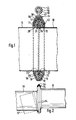
- FIGS. 1-3 connects two pipe ends 10 made of thin-walled round sheet metal pipe.
- Each tube 10 is flanged at its end to form an annular radial ring rim 12.
- a flange ring 14 with a triangular hollow profile rests on each ring rim 12.
- Each flange ring 14 has a radial wall 16 resting against the ring rim 12, a wall 18 returning obliquely to the tube from the outer end of the wall 16 and a wall 20 resting against the tube 10.
- a clamping ring 34 is placed, which is interrupted in the axial direction in a manner not shown, so that it can be expanded and placed on the flange rings.
- the two ends 36 and 38 of the clamping ring 34 overlap when tightening the same in the manner shown in FIG. 1.
- an apron 42 is welded to which a guide sleeve 44 extending in the circumferential direction of the clamping ring 34 is connected.
- the screw part 46 of a screw bracket 48 fixedly connected to the inner clamping ring end 38 is slidably guided.
- the radial wall 16 of the flange ring 14 parallel to the ring rim 12 has a radially inner free edge 22 which, together with the free edge 24 of the wall 20 running parallel to the pipe end 10, forms a slot 26 into which the ring rim 12 is inserted.
- the hollow profile of the flange ring 14 is filled with a sealing compound 23, in which the ring rim 12 is largely embedded.
- the radial wall 16 of the flange ring 14 is designed as a double wall and has two partial walls 16 ⁇ and 17 ⁇ which run approximately parallel to one another or are slightly inclined to one another due to the pressing in of the ring rim 12 and lie on both sides of the ring rim 12. From the outer end of the partial wall 16 ', the wall 18 leading back obliquely to the pipe end 10 extends, and the wall 20 adjoining the pipe end 10 adjoins it. At the end of the wall 20 to be located towards the partial wall 16 ⁇ , the radially outwardly facing partial wall 17 ⁇ adjoins, at the radially outer end of which the second free edge of the flange ring 14 is located.
- the annular rim 12 is inserted into the slot 26 ⁇ between the partial walls 16 ⁇ and 17 ⁇ of the flange ring 14. This insertion can be done with a press fit, so that in any case the flange ring 14 is firmly fixed on the pipe end 10.
- a sealing compound 23 ⁇ is introduced, in which the ring rim 23 is largely embedded.
- the sealing compound 23 ⁇ is, like the sealing compound 23 in the exemplary embodiment in FIG. 3, largely protected against mechanical damage and external stress. This ensures a tight and permanent connection of the flange rings to the pipe ends.
- the clamping ring 34 which is already a closed ring with overlapping ends but is opened as far as possible, is hung over the flange ring 14 of the already firmly mounted pipe section 10 in the manner shown in FIG. 2. Then the not yet firmly installed pipe section 10 in the oblique position 10 ⁇ shown in dashed lines in FIG. 2 is hung from below with its flange ring 14 into the tension ring 34 hanging loosely on the opposite pipe end and then tilted upwards into the position shown in solid lines. The clamping ring 34 can then be tightened in a manner not shown, as a result of which the two connecting flanges 14 are pressed against one another, preferably with the interposition of a seal (not shown).
Landscapes
- Engineering & Computer Science (AREA)
- General Engineering & Computer Science (AREA)
- Mechanical Engineering (AREA)
- Flanged Joints, Insulating Joints, And Other Joints (AREA)
- Transition And Organic Metals Composition Catalysts For Addition Polymerization (AREA)
- Butt Welding And Welding Of Specific Article (AREA)
- Non-Disconnectible Joints And Screw-Threaded Joints (AREA)
- Infusion, Injection, And Reservoir Apparatuses (AREA)
- Storage Of Web-Like Or Filamentary Materials (AREA)
- Joining Of Corner Units Of Frames Or Wings (AREA)
Priority Applications (1)
| Application Number | Priority Date | Filing Date | Title |
|---|---|---|---|
| AT88101285T ATE52317T1 (de) | 1987-04-22 | 1988-01-29 | Stossverbindung zwischen zwei duennwandigen runden blechrohrabschnitten. |
Applications Claiming Priority (2)
| Application Number | Priority Date | Filing Date | Title |
|---|---|---|---|
| DE19873713461 DE3713461A1 (de) | 1987-04-22 | 1987-04-22 | Stossverbindung zwischen zwei duennwandigen runden blechrohrabschnitten |
| DE3713461 | 1987-04-22 |
Publications (2)
| Publication Number | Publication Date |
|---|---|
| EP0287755A1 true EP0287755A1 (fr) | 1988-10-26 |
| EP0287755B1 EP0287755B1 (fr) | 1990-04-25 |
Family
ID=6326059
Family Applications (1)
| Application Number | Title | Priority Date | Filing Date |
|---|---|---|---|
| EP88101285A Expired - Lifetime EP0287755B1 (fr) | 1987-04-22 | 1988-01-29 | Raccord bout à bout entre deux tubes de tôle mince |
Country Status (9)
| Country | Link |
|---|---|
| US (1) | US4822083A (fr) |
| EP (1) | EP0287755B1 (fr) |
| JP (1) | JPH0772596B2 (fr) |
| AT (1) | ATE52317T1 (fr) |
| AU (1) | AU609801B2 (fr) |
| CA (1) | CA1300663C (fr) |
| DE (2) | DE3713461A1 (fr) |
| DK (1) | DK171833B1 (fr) |
| ES (1) | ES2015603B3 (fr) |
Cited By (4)
| Publication number | Priority date | Publication date | Assignee | Title |
|---|---|---|---|---|
| WO1997023743A3 (fr) * | 1995-12-21 | 1997-08-07 | Meinig Metu System | Joint droit pour sections de conduits d'air |
| EP0849518A1 (fr) * | 1996-12-20 | 1998-06-24 | Lindab AB | Procédé et dispositif de raccordement de canalisations |
| US6062610A (en) * | 1995-12-18 | 2000-05-16 | Lindab Ab | Device for the coupling together of pipes |
| US6073977A (en) * | 1994-09-08 | 2000-06-13 | Lindab Ab | Device for coupling pipe sections |
Families Citing this family (11)
| Publication number | Priority date | Publication date | Assignee | Title |
|---|---|---|---|---|
| CH681318A5 (fr) * | 1990-03-20 | 1993-02-26 | Straub Federnfabrik | |
| DE59203992D1 (de) * | 1992-01-16 | 1995-11-16 | Straub Federnfabrik | Rohrkupplung. |
| EP1298374B2 (fr) † | 2001-09-28 | 2011-08-24 | LBF Lufttechnik GmbH | Système de tuyaux et collier de serrage pour système de tuyaux |
| DE10215112C1 (de) * | 2002-04-05 | 2003-09-25 | Meinig Metu System | Stossverbindung zwischen zwei Rohrabschnitten aus Blech und Verfahren zu deren Herstellung |
| DE102005008604A1 (de) * | 2005-02-23 | 2006-08-24 | Smitka, Günter | System für Klimatisierungskanäle |
| US11274777B2 (en) | 2009-06-12 | 2022-03-15 | Romac Industries, Inc. | Pipe coupling |
| US8448993B2 (en) * | 2009-06-12 | 2013-05-28 | Romac Industries, Inc. | Pipe coupling |
| FR2963404B1 (fr) * | 2010-07-27 | 2014-02-07 | Caillau Ets | Systeme de serrage pour le raccordement et le pre-montage d'un premier et d'un deuxieme tube |
| US8894100B2 (en) | 2012-03-16 | 2014-11-25 | Romac Industries, Inc. | Fitting with draw mechanism |
| JP7083998B2 (ja) * | 2019-04-09 | 2022-06-14 | 三恵技研工業株式会社 | 管端部材、フランジ管及びフランジ管のバンド継手構造 |
| CN113550932B (zh) * | 2021-09-02 | 2024-02-02 | 浙江志江风机有限公司 | 一种拼接式风筒 |
Citations (3)
| Publication number | Priority date | Publication date | Assignee | Title |
|---|---|---|---|---|
| DE890588C (de) * | 1950-08-22 | 1953-09-21 | Max Dr-Ing Natter | Luttenverbindung |
| DE3314064A1 (de) * | 1983-04-19 | 1984-10-25 | Karl Meinig KG, 7201 Rietheim-Weilheim | Stossverbindung zwischen zwei blechrohrabschnitten |
| DE3537504C1 (en) * | 1985-10-22 | 1987-07-02 | Meinig Kg Karl | Butt joint between two thin-walled, round sheet-metal tube portions |
Family Cites Families (8)
| Publication number | Priority date | Publication date | Assignee | Title |
|---|---|---|---|---|
| CA678347A (en) * | 1964-01-21 | Flexonics Corporation | Coupling construction | |
| GB561684A (en) * | 1942-05-12 | 1944-05-31 | James Pickford | Improvements in or relating to pipe joints |
| US3498649A (en) * | 1967-08-16 | 1970-03-03 | Anton Pfeuffer | Pipe clamping and centering device |
| US3674291A (en) * | 1970-11-30 | 1972-07-04 | Lockheed Aircraft Corp | Flange for conduit coupling |
| DE2535153A1 (de) * | 1975-08-04 | 1977-02-24 | Herbst Donald | Flanschverbindung fuer kanalabschnitte von lueftungs- und klimatisierkanaelen |
| DE2758295C2 (de) * | 1977-12-27 | 1987-04-16 | Günter 5860 Iserlohn Smitka | Flanschverbindung zum gegenseitigen Befestigen von im Querschnitt im wesentlichen rechteckigen Kanalteilstücken aus Blech |
| DE3113912A1 (de) * | 1981-04-07 | 1982-10-28 | Günter 7518 Bretten Hemmrich | Vorrichtung zur dichten verbindung zweier hohlkoerper |
| DE3515737A1 (de) * | 1985-05-02 | 1986-11-06 | Karl Meinig KG, 7201 Rietheim-Weilheim | Flanschring fuer rohre |
-
1987
- 1987-04-22 DE DE19873713461 patent/DE3713461A1/de active Granted
-
1988
- 1988-01-29 DE DE8888101285T patent/DE3860110D1/de not_active Expired - Fee Related
- 1988-01-29 ES ES88101285T patent/ES2015603B3/es not_active Expired - Lifetime
- 1988-01-29 AT AT88101285T patent/ATE52317T1/de not_active IP Right Cessation
- 1988-01-29 EP EP88101285A patent/EP0287755B1/fr not_active Expired - Lifetime
- 1988-03-10 CA CA000561176A patent/CA1300663C/fr not_active Expired - Fee Related
- 1988-04-11 US US07/179,868 patent/US4822083A/en not_active Expired - Lifetime
- 1988-04-20 DK DK213388A patent/DK171833B1/da not_active IP Right Cessation
- 1988-04-22 JP JP63098444A patent/JPH0772596B2/ja not_active Expired - Fee Related
- 1988-04-22 AU AU15095/88A patent/AU609801B2/en not_active Ceased
Patent Citations (3)
| Publication number | Priority date | Publication date | Assignee | Title |
|---|---|---|---|---|
| DE890588C (de) * | 1950-08-22 | 1953-09-21 | Max Dr-Ing Natter | Luttenverbindung |
| DE3314064A1 (de) * | 1983-04-19 | 1984-10-25 | Karl Meinig KG, 7201 Rietheim-Weilheim | Stossverbindung zwischen zwei blechrohrabschnitten |
| DE3537504C1 (en) * | 1985-10-22 | 1987-07-02 | Meinig Kg Karl | Butt joint between two thin-walled, round sheet-metal tube portions |
Cited By (7)
| Publication number | Priority date | Publication date | Assignee | Title |
|---|---|---|---|---|
| US6073977A (en) * | 1994-09-08 | 2000-06-13 | Lindab Ab | Device for coupling pipe sections |
| US6062610A (en) * | 1995-12-18 | 2000-05-16 | Lindab Ab | Device for the coupling together of pipes |
| WO1997023743A3 (fr) * | 1995-12-21 | 1997-08-07 | Meinig Metu System | Joint droit pour sections de conduits d'air |
| US6109665A (en) * | 1995-12-21 | 2000-08-29 | Metu-System Meining Kg | Butt joint of air duct sections |
| CN1078942C (zh) * | 1995-12-21 | 2002-02-06 | 梅图系统迈尼格两合公司 | 风道段的对接 |
| EP0849518A1 (fr) * | 1996-12-20 | 1998-06-24 | Lindab AB | Procédé et dispositif de raccordement de canalisations |
| US6030005A (en) * | 1996-12-20 | 2000-02-29 | Lindab Ab | Method and device for coupling pipes |
Also Published As
| Publication number | Publication date |
|---|---|
| AU609801B2 (en) | 1991-05-09 |
| AU1509588A (en) | 1988-10-27 |
| DK171833B1 (da) | 1997-06-23 |
| DE3713461A1 (de) | 1988-11-10 |
| ATE52317T1 (de) | 1990-05-15 |
| US4822083A (en) | 1989-04-18 |
| ES2015603B3 (es) | 1990-09-01 |
| EP0287755B1 (fr) | 1990-04-25 |
| DE3860110D1 (de) | 1990-05-31 |
| JPH0772596B2 (ja) | 1995-08-02 |
| DK213388D0 (da) | 1988-04-20 |
| DK213388A (da) | 1988-10-23 |
| DE3713461C2 (fr) | 1989-12-14 |
| CA1300663C (fr) | 1992-05-12 |
| JPS63280990A (ja) | 1988-11-17 |
Similar Documents
| Publication | Publication Date | Title |
|---|---|---|
| EP0287755B1 (fr) | Raccord bout à bout entre deux tubes de tôle mince | |
| EP0443193B1 (fr) | Raccord droit entre deux sections de canaux d'air en tôle | |
| EP2054558B1 (fr) | Dispositif de drainage | |
| DE3143893C1 (de) | Flanschring fuer Rohre | |
| DE2556048A1 (de) | Skelett fuer metallschrank | |
| DE19547982A1 (de) | Stoßverbindung von Luftkanalabschnitten | |
| EP0616162B1 (fr) | Tuyau en tÔle à paroi mince pourvu d'un anneau de bride en une pièce | |
| DE19548341C1 (de) | Starre Verbindung von Bauteilen bei einem Kraftfahrzeug und ein Werkzeug zur Herstellung der Verbindung | |
| EP0467066B1 (fr) | Structure de mur-rideau constitué d'éléments | |
| DE19633435C1 (de) | Schneckengewindeschelle | |
| DE10301018B4 (de) | Anordnung zum Verbinden eines rohrförmigen ersten Bauteils mit einem zweiten Bauteil sowie Verfahren zur Herstellung einer solchen Anordnung | |
| DE2233102C3 (de) | Rohrverbindung sowie Verfahren und Verbindungshülse zur Herstellung der Rohrverbindung | |
| DE69213372T2 (de) | Verfahren und Vorrichtung zum Herstellen von Aussparungen in Betonmauer | |
| DE3537504C1 (en) | Butt joint between two thin-walled, round sheet-metal tube portions | |
| DE102008063582A1 (de) | Rohrschelle | |
| EP0905426A2 (fr) | Dispositif d'étanchéité pour un passage de conduite à travers une ouverture murale | |
| DE3916916A1 (de) | Vorrichtung zur fluessigkeitsdichten verbindung eines rohres mit einer flanschmuffe oder einem flanschrohr | |
| DE29806952U1 (de) | Abstandshalter für Kamineinsatzrohr | |
| WO2008080703A2 (fr) | Ferrure d'assemblage pour assembler deux panneaux de meuble | |
| DE3314064A1 (de) | Stossverbindung zwischen zwei blechrohrabschnitten | |
| DE19842328C2 (de) | Einteiliges Dichtungselement für Rohrverbindungen | |
| DE2706292A1 (de) | Dichteinsatz fuer muffenrohre | |
| DE69204441T2 (de) | Verbindungsmanschette und Montageverfahren. | |
| DE20108823U1 (de) | Verschraubbarer Abzweig für dünnwandige Kanalrohre | |
| DE3704142C2 (fr) |
Legal Events
| Date | Code | Title | Description |
|---|---|---|---|
| PUAI | Public reference made under article 153(3) epc to a published international application that has entered the european phase |
Free format text: ORIGINAL CODE: 0009012 |
|
| AK | Designated contracting states |
Kind code of ref document: A1 Designated state(s): AT BE CH DE ES FR GB IT LI NL SE |
|
| 17P | Request for examination filed |
Effective date: 19881123 |
|
| 17Q | First examination report despatched |
Effective date: 19890809 |
|
| ITF | It: translation for a ep patent filed | ||
| GRAA | (expected) grant |
Free format text: ORIGINAL CODE: 0009210 |
|
| AK | Designated contracting states |
Kind code of ref document: B1 Designated state(s): AT BE CH DE ES FR GB IT LI NL SE |
|
| REF | Corresponds to: |
Ref document number: 52317 Country of ref document: AT Date of ref document: 19900515 Kind code of ref document: T |
|
| GBT | Gb: translation of ep patent filed (gb section 77(6)(a)/1977) | ||
| REF | Corresponds to: |
Ref document number: 3860110 Country of ref document: DE Date of ref document: 19900531 |
|
| ET | Fr: translation filed | ||
| PLBE | No opposition filed within time limit |
Free format text: ORIGINAL CODE: 0009261 |
|
| STAA | Information on the status of an ep patent application or granted ep patent |
Free format text: STATUS: NO OPPOSITION FILED WITHIN TIME LIMIT |
|
| 26N | No opposition filed | ||
| ITTA | It: last paid annual fee | ||
| EAL | Se: european patent in force in sweden |
Ref document number: 88101285.0 |
|
| REG | Reference to a national code |
Ref country code: GB Ref legal event code: IF02 |
|
| PGFP | Annual fee paid to national office [announced via postgrant information from national office to epo] |
Ref country code: AT Payment date: 20030110 Year of fee payment: 16 |
|
| PGFP | Annual fee paid to national office [announced via postgrant information from national office to epo] |
Ref country code: NL Payment date: 20030120 Year of fee payment: 16 Ref country code: FR Payment date: 20030120 Year of fee payment: 16 |
|
| PGFP | Annual fee paid to national office [announced via postgrant information from national office to epo] |
Ref country code: SE Payment date: 20030128 Year of fee payment: 16 Ref country code: BE Payment date: 20030128 Year of fee payment: 16 |
|
| PGFP | Annual fee paid to national office [announced via postgrant information from national office to epo] |
Ref country code: ES Payment date: 20030130 Year of fee payment: 16 |
|
| PGFP | Annual fee paid to national office [announced via postgrant information from national office to epo] |
Ref country code: GB Payment date: 20030203 Year of fee payment: 16 |
|
| PGFP | Annual fee paid to national office [announced via postgrant information from national office to epo] |
Ref country code: DE Payment date: 20030227 Year of fee payment: 16 |
|
| PGFP | Annual fee paid to national office [announced via postgrant information from national office to epo] |
Ref country code: CH Payment date: 20030429 Year of fee payment: 16 |
|
| PG25 | Lapsed in a contracting state [announced via postgrant information from national office to epo] |
Ref country code: GB Free format text: LAPSE BECAUSE OF NON-PAYMENT OF DUE FEES Effective date: 20040129 Ref country code: AT Free format text: LAPSE BECAUSE OF NON-PAYMENT OF DUE FEES Effective date: 20040129 |
|
| PG25 | Lapsed in a contracting state [announced via postgrant information from national office to epo] |
Ref country code: SE Free format text: LAPSE BECAUSE OF NON-PAYMENT OF DUE FEES Effective date: 20040130 Ref country code: ES Free format text: LAPSE BECAUSE OF NON-PAYMENT OF DUE FEES Effective date: 20040130 |
|
| PG25 | Lapsed in a contracting state [announced via postgrant information from national office to epo] |
Ref country code: LI Free format text: LAPSE BECAUSE OF NON-PAYMENT OF DUE FEES Effective date: 20040131 Ref country code: CH Free format text: LAPSE BECAUSE OF NON-PAYMENT OF DUE FEES Effective date: 20040131 Ref country code: BE Free format text: LAPSE BECAUSE OF NON-PAYMENT OF DUE FEES Effective date: 20040131 |
|
| BERE | Be: lapsed |
Owner name: *METU-SYSTEM MEINIG K.G. Effective date: 20040131 |
|
| PG25 | Lapsed in a contracting state [announced via postgrant information from national office to epo] |
Ref country code: NL Free format text: LAPSE BECAUSE OF NON-PAYMENT OF DUE FEES Effective date: 20040801 |
|
| PG25 | Lapsed in a contracting state [announced via postgrant information from national office to epo] |
Ref country code: DE Free format text: LAPSE BECAUSE OF NON-PAYMENT OF DUE FEES Effective date: 20040803 |
|
| EUG | Se: european patent has lapsed | ||
| GBPC | Gb: european patent ceased through non-payment of renewal fee |
Effective date: 20040129 |
|
| REG | Reference to a national code |
Ref country code: CH Ref legal event code: PL |
|
| PG25 | Lapsed in a contracting state [announced via postgrant information from national office to epo] |
Ref country code: FR Free format text: LAPSE BECAUSE OF NON-PAYMENT OF DUE FEES Effective date: 20040930 |
|
| NLV4 | Nl: lapsed or anulled due to non-payment of the annual fee |
Effective date: 20040801 |
|
| REG | Reference to a national code |
Ref country code: FR Ref legal event code: ST |
|
| PG25 | Lapsed in a contracting state [announced via postgrant information from national office to epo] |
Ref country code: IT Free format text: LAPSE BECAUSE OF NON-PAYMENT OF DUE FEES;WARNING: LAPSES OF ITALIAN PATENTS WITH EFFECTIVE DATE BEFORE 2007 MAY HAVE OCCURRED AT ANY TIME BEFORE 2007. THE CORRECT EFFECTIVE DATE MAY BE DIFFERENT FROM THE ONE RECORDED. Effective date: 20050129 |
|
| REG | Reference to a national code |
Ref country code: ES Ref legal event code: FD2A Effective date: 20040130 |