EP0849518A1 - Procédé et dispositif de raccordement de canalisations - Google Patents
Procédé et dispositif de raccordement de canalisations Download PDFInfo
- Publication number
- EP0849518A1 EP0849518A1 EP97850173A EP97850173A EP0849518A1 EP 0849518 A1 EP0849518 A1 EP 0849518A1 EP 97850173 A EP97850173 A EP 97850173A EP 97850173 A EP97850173 A EP 97850173A EP 0849518 A1 EP0849518 A1 EP 0849518A1
- Authority
- EP
- European Patent Office
- Prior art keywords
- sealing ring
- clamping band
- beads
- bead
- circumferential
- Prior art date
- Legal status (The legal status is an assumption and is not a legal conclusion. Google has not performed a legal analysis and makes no representation as to the accuracy of the status listed.)
- Granted
Links
- 230000008878 coupling Effects 0.000 title claims abstract description 18
- 238000010168 coupling process Methods 0.000 title claims abstract description 18
- 238000005859 coupling reaction Methods 0.000 title claims abstract description 18
- 238000000034 method Methods 0.000 title claims abstract description 18
- 239000011324 bead Substances 0.000 claims abstract description 84
- 238000007789 sealing Methods 0.000 claims abstract description 51
- 230000007246 mechanism Effects 0.000 description 8
- 230000008901 benefit Effects 0.000 description 7
- 238000009423 ventilation Methods 0.000 description 4
- 238000013459 approach Methods 0.000 description 1
- 238000010420 art technique Methods 0.000 description 1
- 238000004140 cleaning Methods 0.000 description 1
- 238000010276 construction Methods 0.000 description 1
- 230000033001 locomotion Effects 0.000 description 1
- 239000000463 material Substances 0.000 description 1
- 238000012986 modification Methods 0.000 description 1
- 230000004048 modification Effects 0.000 description 1
Images


Classifications
-
- F—MECHANICAL ENGINEERING; LIGHTING; HEATING; WEAPONS; BLASTING
- F16—ENGINEERING ELEMENTS AND UNITS; GENERAL MEASURES FOR PRODUCING AND MAINTAINING EFFECTIVE FUNCTIONING OF MACHINES OR INSTALLATIONS; THERMAL INSULATION IN GENERAL
- F16L—PIPES; JOINTS OR FITTINGS FOR PIPES; SUPPORTS FOR PIPES, CABLES OR PROTECTIVE TUBING; MEANS FOR THERMAL INSULATION IN GENERAL
- F16L23/00—Flanged joints
- F16L23/04—Flanged joints the flanges being connected by members tensioned in the radial plane
-
- F—MECHANICAL ENGINEERING; LIGHTING; HEATING; WEAPONS; BLASTING
- F24—HEATING; RANGES; VENTILATING
- F24F—AIR-CONDITIONING; AIR-HUMIDIFICATION; VENTILATION; USE OF AIR CURRENTS FOR SCREENING
- F24F13/00—Details common to, or for air-conditioning, air-humidification, ventilation or use of air currents for screening
- F24F13/02—Ducting arrangements
- F24F13/0209—Ducting arrangements characterised by their connecting means, e.g. flanges
Definitions
- the present invention relates to a method and a device for coupling two pipes, which at their end have an outwardly directed circumferential bead, use being made of an annular clamping band which is tightened around the end beads which are arranged end to end, thereby establishing a seal between the clamping band and the end beads.
- An object of the present invention therefore is to provide a method for coupling together pipes having end beads, which is improved compared with prior art.
- a further object of the invention is to provide an improved device for such coupling together.
- the sealing ring is first used to fix the clamping band to a free end bead or to keep two end beads arranged end to end together.
- the mounting of the clamping band is simplified to a considerable extent and the drawbacks which the fitters have experienced till now are obviated. Thanks to the fact that, contrary to the technique that has been prevalent so far, the sealing ring is given a closed, endless form, the sealing problems are reduced.
- the invention is applicable to many different types of piping system, for instance ventilation duct systems and duct systems for conveying finely divided materials.
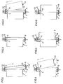
- Figs 1-6 illustrate a first embodiment of the invention, Fig. 1 showing a cylindrical pipe 1 with an outwardly directed circumferential end bead 2, on which an annular clamping band 3 is applied.
- the clamping band 3 may be of the type as shown in Fig. 8 or Fig. 9, as will be described in more detail below.
- the pipe 1 may consist of, for instance, a fixedly mounted pipe included in a ventilation duct system, in which the invention is applied.
- the clamping band 3 is substantially U-shaped in cross-section with two radially inwardly directed flanges 4, 5, between which a sealing ring 6 is placed, which is fixed to the inside of the web 7 of the clamping band 3.
- the sealing ring 6, which is of the cross-section shown in Fig. 14, is endlessly circumferential and elastic and is preferably made of rubber. As is best seen from Fig. 14, the annular seal 6 has two circumferential cup-shaped portions or recesses 8, 9 for abutment against end beads of the pipes where the clamping band 3 is used. Further the seal 6 has a central, circumferential inwardly directed ridge 10 and two similar outer ridges 11, 12 which will be described below.
- a clamping mechanism 13 which is of a type known per se and which need not be described in more detail here.
- An alternative clamping mechanism 13' is shown in Fig. 9.
- the device shown in Figs 1-6 is intended for coupling the first pipe 1 to a second cylindrical pipe 14 provided with an outwardly directed circumferential end bead 15 (see Fig. 3).
- the pipe 14 is a loose pipe which the fitter should connect to the fixed pipe 1.
- the second pipe 14 constitutes an extension of the first pipe 1.
- the clamping band 3 is first placed on a circumferential portion of the end bead 2 of the first pipe 1, one recess 8 of the sealing ring 6 forming a first sealing portion and engaging said circumferential portion (Fig. 1). Subsequently, the clamping band 3 is pivoted in the direction of arrow A to the position shown in Fig. 2, where the recess 8 of the seal 6 completely encompasses and engages around the bead 2.
- the clamping band 3 is fixed to the bead 2 in such a manner that the second recess 9 of the sealing ring 6 is positioned axially outside the end bead 2 and forms an opening, in which the end bead 15 of the loose pipe 14 can easily be put in place.
- the clamping band 3 When applying the method according to the second embodiment of the invention as shown in Fig. 7, the clamping band 3 is first placed axially a distance up on the loose pipe 14, whereupon the two pipes 1, 14 are arranged end to end such that the end beads 2, 15 are positioned axially opposite to each other. The clamping band 3 is then moved axially in the direction of arrow C to a position radially outside the end beads 2, 15 and is finally tightened around these. Otherwise, this embodiment of the invention functions in the same manner as the above-described first embodiment.
- the second embodiment confers great advantages since the fitter in a few simple operations can put the clamping band 3 in place.
- the fitter can simultaneously hold the clamping band 3 and the loose pipe 14 and arrange the beads 2, 15 against each other, whereupon the clamping band 3 can easily be moved in place.
- Fig. 8 is a side view of the clamping band 3 and shows that the sealing ring 6 in its non-tightened state has a smaller inner diameter than the clamping band 3. With a view to ensuring satisfactory clamping of the seal 6, it has, in its non-tightened state, also a smaller inner diameter than the outer diameter of the two end beads 2, 15.
- the seal 6 is fixed to the inside of the clamping band 3 through the angle of an arc which slightly exceeds 270°.
- the two points 16, 17, in which the seal 6 begins to go clear of the inside of the clamping band 6 can in an alternative embodiment (not shown) be closer to the clamping mechanism 13 such that the outer diameter of the seal 6 in this position approaches the inner diameter of the clamping band 3.
- Fig. 8 also shows an extra sealing element 18 which in its clamped state promotes the sealing of the joint between the two end portions of the clamping band 3, which are pulled towards each other in a known manner as the clamping band 3 is tightened.
- Fig. 9 shows another clamping band 3', which is of the same fundamental composition as the clamping band 3 in Fig. 8, but has a different clamping mechanism 13'.
- the method according to the third embodiment of the invention is shown in Figs 10-13, the sealing ring 6 and the clamping band 3 constituting separate parts.
- the seal 6 is applied on the first bead 2, whereupon the second bead 15 is made to engage the seal 6 such that this is clamped around and keeps together the two end beads 2, 15 engaging each other (see Fig. 12).
- the clamping force of the sealing ring 6 around the end beads 2, 15 is in some cases so great that it accomplishes on its own a coupling together of the two pipes 1, 14.
- the clamping band 3 is applied on the outside of the seal 6 (Fig. 13) and is tightened in the same manner as described above.
- This third embodiment confers essentially the same advantages as have been indicated above and should be preferred in the cases where the clamping band 3 and the seal 6 need not necessarily constitute a unit.
- the inner diameter of the seal 6 in its non-tightened state is, as mentioned above, smaller than the outer diameter of the beads 2, 15.
- the seal 6 must be expanded before being applied on the beads 2, 15 (cf. Figs 8 and 9).
- a sealing ring 6 having the cross-section as shown in Fig. 14.
- the central ridge 10 is pressed into the circumferential radially outwardly directed space which is defined by the radially outwardly directed boundary surfaces of the beads 2, 15 arranged end to end.
- the ridge 10 promotes a reliable seal of the joint between the ends of the pipes 1, 14 as the clamping band 3 is tightened.
- the central ridge 10 facilitates the pivoting motions of the clamping band 3 as shown in Figs 1 and 4.
- the central ridge 10 has a smaller inner diameter than the two outer ridges 11, 12, which makes the arrangement of the beads 2, 15 in the clamping band 3 easier.
- Figs 15-16 show a clamping band 3 with an alternatively designed seal 6a, which has the form of a band and whose circumferential edge portions 19, 20 are fixed to the free edge portions of the flanges 4, 5.
- the seal 6a In its non-tightened state, the seal 6a is spaced apart from the inside of the clamping band 3, and when arranging the clamping band 3 against the beads 2, 15, the seal 6a is resilient in the direction of said inside (Fig. 16).
- the advantage of this embodiment is that a seal is established also against the outside of the pipes 1, 14, i.e. on both sides of the beads 2, 15, by the edge portions 19, 20 of the seal 6a are being arranged against the pipes 1, 14.
- Figs 17-18 illustrate a further variant which is based on the principle shown in Figs 15-16.
- the seal 6b is fixed in a different manner to the flanges 4, 5 of the clamping band 3.
- This variant where the flanges 4, 5 are bent away from the joint between the beads 2, 15, yields a particularly advantageous holding of the seal 6b.
- the main part of the seal 6a, 6b is placed between the clamping band 3 and the end beads 2, 15 arranged against each other when coupling together the pipes 1-14, whereas in the embodiments shown in Figs 1-16, Fig. 7 and Figs 7-13, the entire seal 6 is placed between the clamping band and the beads.
- the seals 6a and 6b certainly have no cup-shaped recesses of the type that has been described above, but nevertheless the sealing band can be divided on the one hand into a first sealing portion to be arranged against the one bead and, on the other hand, a second sealing portion to be arranged against the other bead.
Landscapes
- Engineering & Computer Science (AREA)
- General Engineering & Computer Science (AREA)
- Mechanical Engineering (AREA)
- Chemical & Material Sciences (AREA)
- Combustion & Propulsion (AREA)
- Flanged Joints, Insulating Joints, And Other Joints (AREA)
- Joints With Sleeves (AREA)
- Mutual Connection Of Rods And Tubes (AREA)
- Joints Allowing Movement (AREA)
- Non-Disconnectible Joints And Screw-Threaded Joints (AREA)
- Drilling And Exploitation, And Mining Machines And Methods (AREA)
Applications Claiming Priority (2)
| Application Number | Priority Date | Filing Date | Title |
|---|---|---|---|
| SE9604749 | 1996-12-20 | ||
| SE9604749A SE508749C2 (sv) | 1996-12-20 | 1996-12-20 | Sätt att hopkoppla två rör |
Publications (2)
| Publication Number | Publication Date |
|---|---|
| EP0849518A1 true EP0849518A1 (fr) | 1998-06-24 |
| EP0849518B1 EP0849518B1 (fr) | 2003-08-27 |
Family
ID=20405105
Family Applications (1)
| Application Number | Title | Priority Date | Filing Date |
|---|---|---|---|
| EP97850173A Expired - Lifetime EP0849518B1 (fr) | 1996-12-20 | 1997-12-12 | Procédé de raccordement de canalisations |
Country Status (6)
| Country | Link |
|---|---|
| US (1) | US6030005A (fr) |
| EP (1) | EP0849518B1 (fr) |
| AT (1) | ATE248314T1 (fr) |
| DE (1) | DE69724392T2 (fr) |
| DK (1) | DK0849518T3 (fr) |
| SE (1) | SE508749C2 (fr) |
Cited By (8)
| Publication number | Priority date | Publication date | Assignee | Title |
|---|---|---|---|---|
| DE10153029A1 (de) * | 2001-10-26 | 2003-05-22 | Knorr Bremse Systeme | Abstützelement |
| FR2833065A1 (fr) * | 2001-12-05 | 2003-06-06 | Caillau Ets | Systeme de serrage pour le raccordement etanche de deux tubes ayant des surfaces d'appui |
| WO2004020891A1 (fr) * | 2002-08-28 | 2004-03-11 | Dinex A/S | Sangle de serrage, jointure d'extremites de tuyaux et systeme d'echappement |
| WO2005001323A1 (fr) * | 2003-06-27 | 2005-01-06 | Lindab Ab | Systeme d'assemblage pour raccordement de tubes |
| WO2008030167A1 (fr) * | 2006-09-08 | 2008-03-13 | Lindab Ab | Agencement destiné à des éléments de tube de raccordement dans un système de conduit de ventilation |
| ITVR20090198A1 (it) * | 2009-11-19 | 2011-05-20 | Alteco S R L | Sistema di chiusura per contenitori metallici e/o tubazioni in pressione |
| EP2894383A1 (fr) * | 2014-01-10 | 2015-07-15 | Metu Meinig AG | Raccord de deux sections de tube à l'aide d'une bague de serrage |
| WO2019201381A1 (fr) | 2018-04-20 | 2019-10-24 | Elringklinger Ag | Dispositif de serrage pour assurer l'étanchéité et le raccordement de deux tuyaux |
Families Citing this family (14)
| Publication number | Priority date | Publication date | Assignee | Title |
|---|---|---|---|---|
| US6877780B2 (en) | 2000-06-23 | 2005-04-12 | Breeze-Torca Products, Llc | Clamp for joining tubular bodies |
| EP1298374B2 (fr) † | 2001-09-28 | 2011-08-24 | LBF Lufttechnik GmbH | Système de tuyaux et collier de serrage pour système de tuyaux |
| US6832786B2 (en) | 2001-10-16 | 2004-12-21 | D.J. Mielke, Inc. | Tubular member coupling device |
| US6709021B2 (en) * | 2001-10-16 | 2004-03-23 | D.J. Mielke, Inc. | Tubular member coupling device |
| US20100013217A1 (en) * | 2008-07-16 | 2010-01-21 | Cummins Filtration Ip, Inc. | Tube joint and method of joining tubes in an engine exhaust system |
| US9285066B2 (en) * | 2009-01-15 | 2016-03-15 | Cheminee Securite International Ltee | Positive pressure pipe coupling |
| US8590944B2 (en) * | 2010-04-15 | 2013-11-26 | GM Global Technology Operations LLC | Band clamp having radial alignment feature |
| FR2963404B1 (fr) * | 2010-07-27 | 2014-02-07 | Caillau Ets | Systeme de serrage pour le raccordement et le pre-montage d'un premier et d'un deuxieme tube |
| DE102011009230B4 (de) * | 2011-01-22 | 2014-11-27 | Norma Germany Gmbh | Verbindungsanordnung und Verfahren zum Herstellen einer Verbindungsanordnung |
| FR2989426B1 (fr) | 2012-04-11 | 2014-03-28 | Snecma | Turbomachine, telle qu'un turboreacteur ou un turbopropulseur d'avion |
| DE102014100861A1 (de) * | 2014-01-27 | 2015-07-30 | Elringklinger Ag | Rohrverbindung |
| US11156219B2 (en) * | 2015-11-10 | 2021-10-26 | Repligen Corporation | Disposable alternating tangential flow filtration units |
| DE102016103986B3 (de) * | 2016-03-04 | 2017-08-24 | Norma Germany Gmbh | Vorpositionierer für eine Profilschelle und Verbindungsanordnung mit einem derartigen Vorpositionierer |
| CN106195480A (zh) * | 2016-08-19 | 2016-12-07 | 四川民生管业有限责任公司 | 簿壁不锈钢管卡箍管件的安装方法及管件 |
Citations (4)
| Publication number | Priority date | Publication date | Assignee | Title |
|---|---|---|---|---|
| US2426423A (en) * | 1945-02-21 | 1947-08-26 | Marman Products Company Inc | Hydraulic coupling |
| US3006663A (en) * | 1958-08-11 | 1961-10-31 | Lee Clay Products Company | Pipe clamp with resilient member |
| US3235293A (en) * | 1965-01-22 | 1966-02-15 | Owens Illinois Glass Co | Glass pipe coupling |
| EP0287755A1 (fr) * | 1987-04-22 | 1988-10-26 | METU-System Meinig KG | Raccord bout à bout entre deux tubes de tôle mince |
Family Cites Families (16)
| Publication number | Priority date | Publication date | Assignee | Title |
|---|---|---|---|---|
| GB549183A (en) * | 1941-10-13 | 1942-11-10 | Kodak Ltd | Improvements in or relating to flexible pipe joints |
| US2699343A (en) * | 1950-12-20 | 1955-01-11 | Bendix Aviat Corp | Quick disconnect mounting |
| US2941823A (en) * | 1954-12-21 | 1960-06-21 | North American Aviation Inc | W-band coupling for flanged pipe |
| US3084959A (en) * | 1959-08-05 | 1963-04-09 | Corning Glass Works | Pipe coupling having a band clamp and resilient sleeve |
| US3479006A (en) * | 1964-11-12 | 1969-11-18 | Halliburton Co | Balanced rotary valve |
| US3334928A (en) * | 1965-03-10 | 1967-08-08 | John D Schmunk | Pipe coupling |
| US3633947A (en) * | 1970-02-20 | 1972-01-11 | Corning Glass Works | Coupling |
| US3788677A (en) * | 1972-03-20 | 1974-01-29 | B Stade | Emission-free exhaust pipe joint and clamp therefor |
| US4135741A (en) * | 1977-10-11 | 1979-01-23 | Corning Glass Works | Armored piping system |
| US4215883A (en) * | 1979-04-11 | 1980-08-05 | Brown Theodore C Sr | Coupling for pipes and fittings |
| DE3267074D1 (en) * | 1981-01-29 | 1985-12-05 | Mage Ag | Tensible socket for pipes |
| SE466415B (sv) * | 1990-01-26 | 1992-02-10 | Asea Atom Ab | Fjaerrmanoevrerbar roerklamma |
| CH681318A5 (fr) * | 1990-03-20 | 1993-02-26 | Straub Federnfabrik | |
| US6073977A (en) * | 1994-09-08 | 2000-06-13 | Lindab Ab | Device for coupling pipe sections |
| JP3465418B2 (ja) * | 1995-05-31 | 2003-11-10 | オイレス工業株式会社 | 差込み継手及びこの差込み継手を組立てる方法 |
| DK9500486U3 (da) * | 1995-12-18 | 1997-04-11 | Lindab As | Indretning til sammenkobling af rørstykker |
-
1996
- 1996-12-20 SE SE9604749A patent/SE508749C2/sv not_active IP Right Cessation
-
1997
- 1997-12-12 DE DE69724392T patent/DE69724392T2/de not_active Expired - Fee Related
- 1997-12-12 AT AT97850173T patent/ATE248314T1/de not_active IP Right Cessation
- 1997-12-12 EP EP97850173A patent/EP0849518B1/fr not_active Expired - Lifetime
- 1997-12-12 DK DK97850173T patent/DK0849518T3/da active
- 1997-12-18 US US08/993,199 patent/US6030005A/en not_active Expired - Fee Related
Patent Citations (4)
| Publication number | Priority date | Publication date | Assignee | Title |
|---|---|---|---|---|
| US2426423A (en) * | 1945-02-21 | 1947-08-26 | Marman Products Company Inc | Hydraulic coupling |
| US3006663A (en) * | 1958-08-11 | 1961-10-31 | Lee Clay Products Company | Pipe clamp with resilient member |
| US3235293A (en) * | 1965-01-22 | 1966-02-15 | Owens Illinois Glass Co | Glass pipe coupling |
| EP0287755A1 (fr) * | 1987-04-22 | 1988-10-26 | METU-System Meinig KG | Raccord bout à bout entre deux tubes de tôle mince |
Cited By (12)
| Publication number | Priority date | Publication date | Assignee | Title |
|---|---|---|---|---|
| DE10153029A1 (de) * | 2001-10-26 | 2003-05-22 | Knorr Bremse Systeme | Abstützelement |
| FR2833065A1 (fr) * | 2001-12-05 | 2003-06-06 | Caillau Ets | Systeme de serrage pour le raccordement etanche de deux tubes ayant des surfaces d'appui |
| WO2003048624A1 (fr) * | 2001-12-05 | 2003-06-12 | Etablissements Caillau | Systeme de serrage pour le raccordement etanche de deux tubes ayant des surfaces d'appui. |
| US7399005B2 (en) | 2001-12-05 | 2008-07-15 | Etablissments Caillau | Clamping system for the sealed connection of two tubes having support surfaces |
| WO2004020891A1 (fr) * | 2002-08-28 | 2004-03-11 | Dinex A/S | Sangle de serrage, jointure d'extremites de tuyaux et systeme d'echappement |
| WO2005001323A1 (fr) * | 2003-06-27 | 2005-01-06 | Lindab Ab | Systeme d'assemblage pour raccordement de tubes |
| WO2008030167A1 (fr) * | 2006-09-08 | 2008-03-13 | Lindab Ab | Agencement destiné à des éléments de tube de raccordement dans un système de conduit de ventilation |
| ITVR20090198A1 (it) * | 2009-11-19 | 2011-05-20 | Alteco S R L | Sistema di chiusura per contenitori metallici e/o tubazioni in pressione |
| EP2325535A1 (fr) * | 2009-11-19 | 2011-05-25 | Alteco S.r.l. | Connexion pour containers en métal et/ou conduits pressurisés |
| EP2894383A1 (fr) * | 2014-01-10 | 2015-07-15 | Metu Meinig AG | Raccord de deux sections de tube à l'aide d'une bague de serrage |
| WO2019201381A1 (fr) | 2018-04-20 | 2019-10-24 | Elringklinger Ag | Dispositif de serrage pour assurer l'étanchéité et le raccordement de deux tuyaux |
| DE102018109617A1 (de) | 2018-04-20 | 2019-10-24 | Elringklinger Ag | Spannvorrichtung zum Abdichten und Verbinden zweier Rohre |
Also Published As
| Publication number | Publication date |
|---|---|
| DE69724392T2 (de) | 2004-06-09 |
| EP0849518B1 (fr) | 2003-08-27 |
| DE69724392D1 (de) | 2003-10-02 |
| SE9604749L (sv) | 1998-06-21 |
| SE508749C2 (sv) | 1998-11-02 |
| SE9604749D0 (sv) | 1996-12-20 |
| US6030005A (en) | 2000-02-29 |
| ATE248314T1 (de) | 2003-09-15 |
| DK0849518T3 (da) | 2003-10-20 |
Similar Documents
| Publication | Publication Date | Title |
|---|---|---|
| EP0849518B1 (fr) | Procédé de raccordement de canalisations | |
| CA2714147C (fr) | Serre-joint a sangle a boulon unique dote d'une nervure centrale a joints et joint a recouvrement de tuyau utilisant le serre-joint | |
| US5230537A (en) | Pipe coupling | |
| US6062610A (en) | Device for the coupling together of pipes | |
| KR20190107065A (ko) | 배기 클램프 및 방법 | |
| GB2098297A (en) | Improvements in or relating to pipe joints | |
| JPH07111229B2 (ja) | パイプ継手 | |
| JPH0355713B2 (fr) | ||
| JP2008531952A (ja) | Vリングインサートを備えたパイプクランプアセンブリ | |
| GB2149037A (en) | Pipe coupling | |
| US5282654A (en) | Pipe coupling sleeve | |
| KR20160072111A (ko) | 파이프 결합구 | |
| EP1281907B1 (fr) | Manchon d'accouplement avec un anneau d'étanchéité comprimé en direction axiale | |
| US6692042B2 (en) | Profiled clamp and sleeve joint comprising such a profiled clamp | |
| US20210324982A1 (en) | Clamp locating system and method | |
| GB2161882A (en) | Pipe couplings | |
| HK1009477A (en) | Method and device for coupling pipes | |
| US5470112A (en) | Adjustable coupling ring | |
| CN114746687A (zh) | 软管夹 | |
| US6390512B1 (en) | Gasket retainer clip | |
| JPH09264473A (ja) | 管継手構造 | |
| EP3702658B1 (fr) | Couplage de tuyaux avec protection contre le cisaillement de pièces de fixation | |
| JP2949334B2 (ja) | ユニオンナット継手用管離脱防止金具 | |
| JP3235816B2 (ja) | 離脱防止管継手 | |
| GB2314393A (en) | Coupling comprising elastomeric strip clamped around pipe ends or fracture |
Legal Events
| Date | Code | Title | Description |
|---|---|---|---|
| PUAI | Public reference made under article 153(3) epc to a published international application that has entered the european phase |
Free format text: ORIGINAL CODE: 0009012 |
|
| AK | Designated contracting states |
Kind code of ref document: A1 Designated state(s): AT BE CH DE DK ES FI FR GB GR IE IT LI NL PT SE |
|
| AX | Request for extension of the european patent |
Free format text: AL;LT;LV;MK;RO;SI |
|
| 17P | Request for examination filed |
Effective date: 19981210 |
|
| AKX | Designation fees paid |
Free format text: AT BE CH DE DK ES FI FR GB GR IE IT LI LU MC NL |
|
| RBV | Designated contracting states (corrected) |
Designated state(s): AT BE CH DE DK ES FI FR GB GR IE IT LI LU MC NL |
|
| RBV | Designated contracting states (corrected) |
Designated state(s): AT BE CH DE DK ES FI FR GB GR IE IT LI NL PT SE |
|
| 17Q | First examination report despatched |
Effective date: 20010328 |
|
| RTI1 | Title (correction) |
Free format text: METHOD FOR COUPLING PIPES |
|
| RTI1 | Title (correction) |
Free format text: METHOD FOR COUPLING PIPES |
|
| GRAH | Despatch of communication of intention to grant a patent |
Free format text: ORIGINAL CODE: EPIDOS IGRA |
|
| GRAH | Despatch of communication of intention to grant a patent |
Free format text: ORIGINAL CODE: EPIDOS IGRA |
|
| GRAA | (expected) grant |
Free format text: ORIGINAL CODE: 0009210 |
|
| AK | Designated contracting states |
Designated state(s): AT BE CH DE DK ES FI FR GB GR IE IT LI NL PT SE |
|
| PG25 | Lapsed in a contracting state [announced via postgrant information from national office to epo] |
Ref country code: NL Free format text: LAPSE BECAUSE OF FAILURE TO SUBMIT A TRANSLATION OF THE DESCRIPTION OR TO PAY THE FEE WITHIN THE PRESCRIBED TIME-LIMIT Effective date: 20030827 Ref country code: LI Free format text: LAPSE BECAUSE OF FAILURE TO SUBMIT A TRANSLATION OF THE DESCRIPTION OR TO PAY THE FEE WITHIN THE PRESCRIBED TIME-LIMIT Effective date: 20030827 Ref country code: IT Free format text: LAPSE BECAUSE OF FAILURE TO SUBMIT A TRANSLATION OF THE DESCRIPTION OR TO PAY THE FEE WITHIN THE PRE;WARNING: LAPSES OF ITALIAN PATENTS WITH EFFECTIVE DATE BEFORE 2007 MAY HAVE OCCURRED AT ANY TIME BEFORE 2007. THE CORRECT EFFECTIVE DATE MAY BE DIFFERENT FROM THE ONE RECORDED.SCRIBED TIME-LIMIT Effective date: 20030827 Ref country code: FR Free format text: LAPSE BECAUSE OF FAILURE TO SUBMIT A TRANSLATION OF THE DESCRIPTION OR TO PAY THE FEE WITHIN THE PRESCRIBED TIME-LIMIT Effective date: 20030827 Ref country code: FI Free format text: LAPSE BECAUSE OF FAILURE TO SUBMIT A TRANSLATION OF THE DESCRIPTION OR TO PAY THE FEE WITHIN THE PRESCRIBED TIME-LIMIT Effective date: 20030827 Ref country code: CH Free format text: LAPSE BECAUSE OF FAILURE TO SUBMIT A TRANSLATION OF THE DESCRIPTION OR TO PAY THE FEE WITHIN THE PRESCRIBED TIME-LIMIT Effective date: 20030827 Ref country code: BE Free format text: LAPSE BECAUSE OF FAILURE TO SUBMIT A TRANSLATION OF THE DESCRIPTION OR TO PAY THE FEE WITHIN THE PRESCRIBED TIME-LIMIT Effective date: 20030827 Ref country code: AT Free format text: LAPSE BECAUSE OF FAILURE TO SUBMIT A TRANSLATION OF THE DESCRIPTION OR TO PAY THE FEE WITHIN THE PRESCRIBED TIME-LIMIT Effective date: 20030827 |
|
| REG | Reference to a national code |
Ref country code: GB Ref legal event code: FG4D |
|
| REG | Reference to a national code |
Ref country code: CH Ref legal event code: EP |
|
| REG | Reference to a national code |
Ref country code: IE Ref legal event code: FG4D |
|
| REF | Corresponds to: |
Ref document number: 69724392 Country of ref document: DE Date of ref document: 20031002 Kind code of ref document: P |
|
| PG25 | Lapsed in a contracting state [announced via postgrant information from national office to epo] |
Ref country code: SE Free format text: LAPSE BECAUSE OF FAILURE TO SUBMIT A TRANSLATION OF THE DESCRIPTION OR TO PAY THE FEE WITHIN THE PRESCRIBED TIME-LIMIT Effective date: 20031127 Ref country code: GR Free format text: LAPSE BECAUSE OF FAILURE TO SUBMIT A TRANSLATION OF THE DESCRIPTION OR TO PAY THE FEE WITHIN THE PRESCRIBED TIME-LIMIT Effective date: 20031127 |
|
| PG25 | Lapsed in a contracting state [announced via postgrant information from national office to epo] |
Ref country code: ES Free format text: LAPSE BECAUSE OF FAILURE TO SUBMIT A TRANSLATION OF THE DESCRIPTION OR TO PAY THE FEE WITHIN THE PRESCRIBED TIME-LIMIT Effective date: 20031208 |
|
| PG25 | Lapsed in a contracting state [announced via postgrant information from national office to epo] |
Ref country code: IE Free format text: LAPSE BECAUSE OF NON-PAYMENT OF DUE FEES Effective date: 20031212 Ref country code: GB Free format text: LAPSE BECAUSE OF NON-PAYMENT OF DUE FEES Effective date: 20031212 |
|
| PGFP | Annual fee paid to national office [announced via postgrant information from national office to epo] |
Ref country code: DK Payment date: 20031222 Year of fee payment: 7 |
|
| PG25 | Lapsed in a contracting state [announced via postgrant information from national office to epo] |
Ref country code: PT Free format text: LAPSE BECAUSE OF FAILURE TO SUBMIT A TRANSLATION OF THE DESCRIPTION OR TO PAY THE FEE WITHIN THE PRESCRIBED TIME-LIMIT Effective date: 20040127 |
|
| NLV1 | Nl: lapsed or annulled due to failure to fulfill the requirements of art. 29p and 29m of the patents act | ||
| REG | Reference to a national code |
Ref country code: CH Ref legal event code: PL |
|
| PLBE | No opposition filed within time limit |
Free format text: ORIGINAL CODE: 0009261 |
|
| STAA | Information on the status of an ep patent application or granted ep patent |
Free format text: STATUS: NO OPPOSITION FILED WITHIN TIME LIMIT |
|
| GBPC | Gb: european patent ceased through non-payment of renewal fee |
Effective date: 20031212 |
|
| 26N | No opposition filed |
Effective date: 20040528 |
|
| EN | Fr: translation not filed | ||
| REG | Reference to a national code |
Ref country code: IE Ref legal event code: MM4A |
|
| PG25 | Lapsed in a contracting state [announced via postgrant information from national office to epo] |
Ref country code: DK Free format text: LAPSE BECAUSE OF NON-PAYMENT OF DUE FEES Effective date: 20050103 |
|
| REG | Reference to a national code |
Ref country code: HK Ref legal event code: WD Ref document number: 1009477 Country of ref document: HK |
|
| REG | Reference to a national code |
Ref country code: DK Ref legal event code: EBP |
|
| PGFP | Annual fee paid to national office [announced via postgrant information from national office to epo] |
Ref country code: DE Payment date: 20061218 Year of fee payment: 10 |
|
| PG25 | Lapsed in a contracting state [announced via postgrant information from national office to epo] |
Ref country code: DE Free format text: LAPSE BECAUSE OF NON-PAYMENT OF DUE FEES Effective date: 20080701 |