EP0287774A2 - Cathode thermionique en épingle à cheveux - Google Patents
Cathode thermionique en épingle à cheveux Download PDFInfo
- Publication number
- EP0287774A2 EP0287774A2 EP88102556A EP88102556A EP0287774A2 EP 0287774 A2 EP0287774 A2 EP 0287774A2 EP 88102556 A EP88102556 A EP 88102556A EP 88102556 A EP88102556 A EP 88102556A EP 0287774 A2 EP0287774 A2 EP 0287774A2
- Authority
- EP
- European Patent Office
- Prior art keywords
- temperature
- apex
- wire
- cathode
- legs
- Prior art date
- Legal status (The legal status is an assumption and is not a legal conclusion. Google has not performed a legal analysis and makes no representation as to the accuracy of the status listed.)
- Withdrawn
Links
- 230000005855 radiation Effects 0.000 claims abstract description 14
- 238000002844 melting Methods 0.000 claims abstract description 3
- 229910052751 metal Inorganic materials 0.000 claims abstract description 3
- 239000002184 metal Substances 0.000 claims abstract description 3
- 230000005680 Thomson effect Effects 0.000 claims description 6
- 230000017525 heat dissipation Effects 0.000 claims description 4
- 238000009826 distribution Methods 0.000 abstract description 10
- 210000002414 leg Anatomy 0.000 description 30
- 238000001704 evaporation Methods 0.000 description 8
- 230000008020 evaporation Effects 0.000 description 7
- 230000000694 effects Effects 0.000 description 6
- WFKWXMTUELFFGS-UHFFFAOYSA-N tungsten Chemical compound [W] WFKWXMTUELFFGS-UHFFFAOYSA-N 0.000 description 6
- 238000004049 embossing Methods 0.000 description 5
- 239000000463 material Substances 0.000 description 4
- 238000010438 heat treatment Methods 0.000 description 3
- 239000000155 melt Substances 0.000 description 3
- 229910052721 tungsten Inorganic materials 0.000 description 3
- 239000010937 tungsten Substances 0.000 description 3
- 238000003466 welding Methods 0.000 description 3
- 239000010406 cathode material Substances 0.000 description 2
- 238000009825 accumulation Methods 0.000 description 1
- 230000002411 adverse Effects 0.000 description 1
- 238000005452 bending Methods 0.000 description 1
- 230000015556 catabolic process Effects 0.000 description 1
- 238000001816 cooling Methods 0.000 description 1
- 230000007423 decrease Effects 0.000 description 1
- 238000006731 degradation reaction Methods 0.000 description 1
- 238000009792 diffusion process Methods 0.000 description 1
- 238000004519 manufacturing process Methods 0.000 description 1
- 230000003287 optical effect Effects 0.000 description 1
- 230000001151 other effect Effects 0.000 description 1
- 238000003825 pressing Methods 0.000 description 1
- 239000003870 refractory metal Substances 0.000 description 1
- 239000007787 solid Substances 0.000 description 1
- 238000004544 sputter deposition Methods 0.000 description 1
- 230000007704 transition Effects 0.000 description 1
- 210000000689 upper leg Anatomy 0.000 description 1
Images


Classifications
-
- H—ELECTRICITY
- H01—ELECTRIC ELEMENTS
- H01J—ELECTRIC DISCHARGE TUBES OR DISCHARGE LAMPS
- H01J1/00—Details of electrodes, of magnetic control means, of screens, or of the mounting or spacing thereof, common to two or more basic types of discharge tubes or lamps
- H01J1/02—Main electrodes
- H01J1/13—Solid thermionic cathodes
- H01J1/15—Cathodes heated directly by an electric current
- H01J1/16—Cathodes heated directly by an electric current characterised by the shape
Definitions
- Hairpin cathodes made from wires of refractory metals, especially tungsten, are now commonly used as standard electron sources, e.g. used in electron microscopes and other electron optical instruments.
- the tungsten hairpin cathodes that are used today in electron microscopes are made of pure or thoriated tungsten wire with a diameter of 0.12 - 0.14 mm.
- the inner bending radius at the apex is usually 0.05 - 0.1 mm.
- This hairpin is connected at both ends of its legs by spot welding to the heating current leads in the cathode base. Both legs should have the same length so that the emitting apex is equidistant from the cold ends of the hairpin and therefore reaches the highest temperature during operation. The greatest material removal should therefore also take place at this point take place by evaporation and the service life can be determined by the temperature and wire thickness at this point.
- the temperature sink at the apex is hardly measurable pyrometrically. It is only a few degrees.
- a prerequisite for the same height of the temperature maxima to the left and right of the apex is that the heat balance in the two legs is exactly symmetrical. If this is not the case, an asymmetrical temperature distribution is created, as shown by the dashed line. This asymmetry intensifies over time, because not only does the increase in resistance due to evaporation on the one hand increase more and more, but also the degradation on the other hand decreases as the temperature at the apex is kept constant. As the dash-dotted line in FIG. 1 shows, the temperature difference will increase until a leg melts away catastrophically.
- the object of the present invention is to extend the life of hairpin cathodes by reducing the temperature drop at the apex and thus the tendency to destabilize the temperature distribution, and reducing the evaporation losses in this area by suitable measures.
- thermionic hairpin cathode made of a high-melting metal wire, which is characterized in that the temperature gradient near the apex is increased by increased heat dissipation along the two legs without reducing the cross-sectional area of the wire.
- the object of the invention is achieved in that the heat radiation at a distance from the apex, which corresponds to 10% to 50% of the leg length, is locally increased by enlarging the surface without appreciably reducing the cross-sectional area of the wire.
- the wire is deformed in the regions of the two legs adjoining the apex (without a substantial change in the cross-sectional area) of the wire in such a way that it obtains a semicircular profile, and at the same time the flat sides of the two sides become as possible are a short distance from each other.
- the temperature gradient starting from the apex along the leg becomes much steeper.
- a temperature distribution as shown in FIG. 2 then results.
- the solid curve shows the original temperature distribution under ideal conditions, and the dashed line shows the distribution after enlarging the surface at a point on the legs that is approximately 2 mm from the apex.
- the total length of the legs was 8 mm.
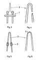
- the local enlargement of the radiating surface is achieved in that tungsten wire spirals 3 of approximately 0.6 mm in length and 0.4 mm in diameter are pushed on at a distance of approximately 2 mm from the apex. To achieve a firm fit, they are pressed a little flat. After the cathode has heated up, they then connect to the wire core by diffusion welding and thus obtain the necessary good thermal contact.
- Figure 6 shows the same cathode at the end of its life after 48 hours of operation at a peak temperature of 2900 K. With this excessive temperature, the test time should be shortened. It can be seen that it was possible to move the point 5 of the highest temperature close to the apex and thereby increase the service life many times over. The lifespan achieved would have been 6 to 7 times at the usual cathode temperature of approx. 2750 K, i.e. 300-350 hours instead of 20-50 hours, provided that the temperature or emission of the cathode is kept constant.
- the local increase in radiation is achieved by pressing the tungsten wire flat. Care must be taken to ensure that the minimum thickness of the flat-pressed area 4 is not fallen below, since otherwise there is a risk that the percentage cross-sectional reduction there per hour will be greater than at the apex and the temperature gradient will gradually disappear due to excessive local resistance increase.
- the flat pressed area In order to achieve a sufficient surface enlargement, the flat pressed area must be longer than the wire spiral in the first example.
- a suitable dimensioning is e.g. an embossing of approx. 1.5 mm length with 0.4 mm width. As in the previous example, this reflects a local surface enlargement of approx. 0.7 mm2.
- FIGS. 8-11 relate to an embodiment in which the apex region of the hairpin cathode was deformed in a die at a temperature of 300-400 ° C. in such a way that the two legs are given a semicircular profile 6, as shown in FIG.
- the embossing is made to a length of 0.3-0.5mm.
- the flat sides touch each other initially and would form a short circuit if the legs were not subsequently spread slightly, so that a wedge-shaped gap 7 of 0-30 ⁇ m in width is created.
- the opposing surfaces can neither radiate appreciably from this narrow gap, nor can considerable amounts of material evaporate to the outside.
- the radiation and evaporation losses of this cathode section are reduced by approximately 25% in this way.
- Embossing the legs has another important advantage.
- An approximately hemispherical cathode end 8 is then formed at the apex of the hairpin.
- a cone or a pyramid 9 can be ground on this hemisphere, as shown in broken lines in FIGS. 8 and 9, so that a tip cathode with a long service life is produced. It even contributes to an increase in the service life if the relatively large accumulation of material at the tip, resulting from the embossing, with its large radiation losses, is reduced to the permissible level in this way and the temperature gradient near the tip is thereby increased.
- FIG. 11 shows the geometry of such a cathode, which is provided with additional cooling spirals as in FIG. 5, but without a ground point, after 50 hours of operation at 2900 K.
- the lifespan is not yet over after this time and it would be significantly extended if the asymmetry of the embossed leg areas were suppressed by grinding a tip and increasing the temperature gradient.
- a suitable solution consists in either deliberately designing the leg length to be different, or in arranging the leg areas with increased radiation at different distances from the apex or in different surface sizes. So that the geometry and current direction remain assigned to one another, the connection points of the current leads on the cathode base would then have to be marked accordingly or made unmistakable.
Landscapes
- Solid Thermionic Cathode (AREA)
- Electron Sources, Ion Sources (AREA)
Applications Claiming Priority (2)
| Application Number | Priority Date | Filing Date | Title |
|---|---|---|---|
| CH158287 | 1987-04-24 | ||
| CH1582/87 | 1987-04-24 |
Publications (2)
| Publication Number | Publication Date |
|---|---|
| EP0287774A2 true EP0287774A2 (fr) | 1988-10-26 |
| EP0287774A3 EP0287774A3 (fr) | 1990-03-07 |
Family
ID=4213784
Family Applications (1)
| Application Number | Title | Priority Date | Filing Date |
|---|---|---|---|
| EP88102556A Withdrawn EP0287774A3 (fr) | 1987-04-24 | 1988-02-22 | Cathode thermionique en épingle à cheveux |
Country Status (3)
| Country | Link |
|---|---|
| US (1) | US4899078A (fr) |
| EP (1) | EP0287774A3 (fr) |
| JP (1) | JPS63308853A (fr) |
Families Citing this family (2)
| Publication number | Priority date | Publication date | Assignee | Title |
|---|---|---|---|---|
| EP1622184B1 (fr) * | 2004-07-28 | 2011-05-18 | ICT Integrated Circuit Testing Gesellschaft für Halbleiterprüftechnik mbH | Emetteur pource source d'ions et procédé pour sa fabrication |
| US7544523B2 (en) * | 2005-12-23 | 2009-06-09 | Fei Company | Method of fabricating nanodevices |
Family Cites Families (5)
| Publication number | Priority date | Publication date | Assignee | Title |
|---|---|---|---|---|
| DE1144418B (de) * | 1961-07-20 | 1963-02-28 | Siemens Planiawerke A G Fuer K | Verfahren zur Herstellung einer Kontaktschicht auf einem silizium-haltigen Werkstoff |
| US3356887A (en) * | 1965-07-30 | 1967-12-05 | Frederick C W Heil | Fe cathode redesign |
| NL7101954A (fr) * | 1971-02-13 | 1972-08-15 | ||
| US3817592A (en) * | 1972-09-29 | 1974-06-18 | Linfield Res Inst | Method for reproducibly fabricating and using stable thermal-field emission cathodes |
| CA1141420A (fr) * | 1980-06-20 | 1983-02-15 | Stephen Lhotsky | Filament, procede d'affutage electrolytique et appareil permettant la mise en oeuvre du procede |
-
1988
- 1988-02-22 EP EP88102556A patent/EP0287774A3/fr not_active Withdrawn
- 1988-04-12 US US07/180,850 patent/US4899078A/en not_active Expired - Fee Related
- 1988-04-21 JP JP63096968A patent/JPS63308853A/ja active Pending
Also Published As
| Publication number | Publication date |
|---|---|
| US4899078A (en) | 1990-02-06 |
| EP0287774A3 (fr) | 1990-03-07 |
| JPS63308853A (ja) | 1988-12-16 |
Similar Documents
| Publication | Publication Date | Title |
|---|---|---|
| DE2727907C2 (fr) | ||
| DE69019793T2 (de) | Xenon-Metallhalogenidlampe, insbesondere geeignet für Kraftfahrzeuganwendungen, mit einer verbesserten Elektrodenstruktur. | |
| EP0451647B1 (fr) | Lampe à décharge à haute pression et son procédé de fabrication | |
| EP1215699A1 (fr) | Lampe à décharge à haute pression et procédé de fabrication | |
| DE69125272T2 (de) | Verbesserte elektrode für metallhalogenidentladungslampe | |
| DE69109101T2 (de) | Metallhalogenidentladungslampe mit bestimmtem schaftlastfaktor. | |
| DE102012209089A1 (de) | Röntgenröhre mit einer Drehanode | |
| DE2128921C3 (de) | Elektrische Hochvakuum-Entladungsrohre mit mindestens zwei nichtemittierenden Elektroden | |
| DE1589106C3 (fr) | ||
| DE60126070T2 (de) | Faserziehvorrichtung mit anschlussklemme und verfahren zur seiner herstellung | |
| DE2449225C3 (de) | Verdampfungstiegel für Vakuumbedampfungs anlagen | |
| DE102015215690B4 (de) | Emitteranordnung | |
| EP0235619B1 (fr) | Cathode à incandescence pour tube à rayons X | |
| EP0024604A1 (fr) | Procédé et dispositif pour le dépôt par évaporation de matériaux électroconducteurs (métaux) sous vide très poussé | |
| DE3043193A1 (de) | Elektrische lampe | |
| DE202023103670U9 (de) | Planarglühfaden mit fokussierter, zentraler Elektronenemission | |
| DE2215784C3 (de) | Direkt geheizte Kathode für Elektronenröhren | |
| DE102014211688A1 (de) | Flachemitter | |
| EP0184876A2 (fr) | Lampe à décharge à gaz à haute pression à électrode en fer blanc de tungstène | |
| DE848673C (de) | Elektrische Hochdruckmetalldampfentladungsroehre | |
| DE102012205715B4 (de) | Elektronenemitter für eine Röntgenröhre und Röntgenröhre mit einem solchen Elektronenemitter | |
| DE616418C (de) | Elektrische Entladungsroehre mit einer durch einen im wesentlichen gestreckten Gluehfaden indirekt geheizten Kathode | |
| DE892185C (de) | Verfahren zur Herstellung einer gutleitenden Verbindung zwischen dem Ende einer Gluehdrahtwendel und einem zur Versteifung dienenden Metallteil | |
| DE818536C (de) | Kathode, insbesondere fuer Elektronen-Entladungsgeraete | |
| DE608696C (de) | Gluehkathode fuer elektrische Entladungsgefaesse |
Legal Events
| Date | Code | Title | Description |
|---|---|---|---|
| PUAI | Public reference made under article 153(3) epc to a published international application that has entered the european phase |
Free format text: ORIGINAL CODE: 0009012 |
|
| AK | Designated contracting states |
Kind code of ref document: A2 Designated state(s): CH DE FR GB LI NL |
|
| PUAL | Search report despatched |
Free format text: ORIGINAL CODE: 0009013 |
|
| AK | Designated contracting states |
Kind code of ref document: A3 Designated state(s): CH DE FR GB LI NL |
|
| 17P | Request for examination filed |
Effective date: 19900329 |
|
| 17Q | First examination report despatched |
Effective date: 19920818 |
|
| STAA | Information on the status of an ep patent application or granted ep patent |
Free format text: STATUS: THE APPLICATION IS DEEMED TO BE WITHDRAWN |
|
| 18D | Application deemed to be withdrawn |
Effective date: 19921229 |