EP0287897B1 - Appareil tournant flexible pour travailler la neige - Google Patents
Appareil tournant flexible pour travailler la neige Download PDFInfo
- Publication number
- EP0287897B1 EP0287897B1 EP88105519A EP88105519A EP0287897B1 EP 0287897 B1 EP0287897 B1 EP 0287897B1 EP 88105519 A EP88105519 A EP 88105519A EP 88105519 A EP88105519 A EP 88105519A EP 0287897 B1 EP0287897 B1 EP 0287897B1
- Authority
- EP
- European Patent Office
- Prior art keywords
- tiller
- snow
- sections
- frame
- hinge
- Prior art date
- Legal status (The legal status is an assumption and is not a legal conclusion. Google has not performed a legal analysis and makes no representation as to the accuracy of the status listed.)
- Expired - Lifetime
Links
- 230000003370 grooming effect Effects 0.000 claims abstract description 12
- 230000002441 reversible effect Effects 0.000 claims description 6
- 230000036346 tooth eruption Effects 0.000 claims description 5
- 238000005096 rolling process Methods 0.000 abstract description 9
- 238000005452 bending Methods 0.000 abstract description 2
- 239000012634 fragment Substances 0.000 description 9
- 230000010355 oscillation Effects 0.000 description 9
- 230000008878 coupling Effects 0.000 description 5
- 238000010168 coupling process Methods 0.000 description 5
- 238000005859 coupling reaction Methods 0.000 description 5
- 239000012530 fluid Substances 0.000 description 5
- 230000001143 conditioned effect Effects 0.000 description 2
- 206010028896 Needle track marks Diseases 0.000 description 1
- 230000000712 assembly Effects 0.000 description 1
- 238000000429 assembly Methods 0.000 description 1
- 238000002485 combustion reaction Methods 0.000 description 1
- 230000003750 conditioning effect Effects 0.000 description 1
- 238000013016 damping Methods 0.000 description 1
- 239000004744 fabric Substances 0.000 description 1
- 230000001788 irregular Effects 0.000 description 1
- 239000002362 mulch Substances 0.000 description 1
- 230000003014 reinforcing effect Effects 0.000 description 1
- 239000011435 rock Substances 0.000 description 1
- 230000035939 shock Effects 0.000 description 1
- 238000003756 stirring Methods 0.000 description 1
Images




Classifications
-
- E—FIXED CONSTRUCTIONS
- E01—CONSTRUCTION OF ROADS, RAILWAYS, OR BRIDGES
- E01H—STREET CLEANING; CLEANING OF PERMANENT WAYS; CLEANING BEACHES; DISPERSING OR PREVENTING FOG IN GENERAL CLEANING STREET OR RAILWAY FURNITURE OR TUNNEL WALLS
- E01H4/00—Working on surfaces of snow or ice in order to make them suitable for traffic or sporting purposes, e.g. by compacting snow
- E01H4/02—Working on surfaces of snow or ice in order to make them suitable for traffic or sporting purposes, e.g. by compacting snow for sporting purposes, e.g. preparation of ski trails; Construction of artificial surfacings for snow or ice sports ; Trails specially adapted for on-the-snow vehicles, e.g. devices adapted for ski-trails
-
- A—HUMAN NECESSITIES
- A01—AGRICULTURE; FORESTRY; ANIMAL HUSBANDRY; HUNTING; TRAPPING; FISHING
- A01B—SOIL WORKING IN AGRICULTURE OR FORESTRY; PARTS, DETAILS, OR ACCESSORIES OF AGRICULTURAL MACHINES OR IMPLEMENTS, IN GENERAL
- A01B33/00—Tilling implements with rotary driven tools, e.g. in combination with fertiliser distributors or seeders, with grubbing chains, with sloping axles, with driven discs
- A01B33/08—Tools; Details, e.g. adaptations of transmissions or gearings
- A01B33/087—Lifting devices; Depth regulation devices; Mountings
Definitions
- the field of the invention is snow conditioning and grooming devices which chop, grind, and stir the snow, and more particularly such devices for producing rolling ski paths by thoroughly grooming uneven snow surfaces without excessively flattening their contours.
- snow-grooming devices have been used to smooth and recondition snow surfaces for ski slopes, generally being drawn over the snow behind a tracked vehicle. Examples are unpowered harrows, rotating discs, rollers and the like to break up and level the snow surface.
- snow tillers are powered to agressively break up and cut the snow so that the conditioned surface is relatively fine grained, and preferably lightly but firmly packed for easy, enjoyable skiing.
- Such tillers comprise elongate, toothed cutter bars mounted on frames and powered to rotate by vehicle power takeoffs, or separate independent combustion or hydraulic engines mounted directly on the tiller frame. See U.S. Patent No. 4,359,831.
- the cutter bar teeth may be radially projecting blades or spikes. In some instances appended lengths of chain are used to mulch the snow surface.
- the tillers are towed by endless track vehicles, and must groom paths of 12 to 16 feet (3.7 to 4.9 m) to cover the track marks.
- the entire path is groomed all across by a rigid cutter bar.
- the rigid cutter bar cannot conform to sinuously rolling snow surfaces, tending to work the high places but bridge over the valleys between. Rolling paths thus tend to be reduced to quite flat ones. It is difficult or impossible to produce uniformly groomed yet rolling paths, which are very enjoyable to ski and are desirably slower and safer.
- Some present tillers do have provisions allowing them to freely rotate about an axis in the direction of travel.
- Patent No. 4,359,831 incorporates an "oscillation" bar and coupling for this purpose.
- Such devices allow the cutters to act somewhat independently of the towing vehicle attitudes to better conform to rough snow surfaces. They fail to alleviate the bridging problem discussed above.
- the two segment, "flexibly coupled" cutter bar of said patent The two axially aligned cutter bar segments are coupled only sufficiently flexible to relieve bearing alignment and frame deflection problems. The coupling flexes only to compensate for any deflection of the tiller frame, so that the cutter segments remain substantially aligned. The bridging problem is therefore not substantially relieved.
- high flexure couplings appear to be also required at the outside ends of the cutter bar, and the constantly changing distance between these ends must somehow be accommodated.
- the coupled two part cutter bar can bend with respect to its mounting frame, to somewhat alleviate the bridging.
- the frame is believed to be rigid and monolithic.
- the attached snow apron and grooming or compactor bar are also monolithic and therefore cannot follow the flexing cutter bar, so that any grooming advantages are largely cancelled.
- a flexible tiller which in its presently preferred embodiment comprises a center and two side sections, each one being a complete tiller unit including at least a cutter bar and an associated frame, and preferably also an apron and a grooming bar or other following grooming provisions.
- the tiller center section is preferably adapted to be secured to a towing vehicle in a manner permitting it to freely rotate about a forwardly directed, central horizontal axis.
- Each of the two tiller end sections are connected flexibly to ends of the tiller center section by frame to frame hinges and by cutter bar to cutter bar universally flexing joints.
- Each universal joint is located on the axis of the associated hinge, so that each end tiller section can rotate freely as a unit about the hinge.
- the oscillating center section and the two privotally attached end sections deflect cooperatively in response to the snow contours to enable the cutter bars to closely conform to and thorougly groom rolling snow paths without reducing them to flat ones.
- the rolling paths are enjoyable to ski, and are slower and safer.
- the universal joints enable the three cutter bar sections, regardless of their condition of alignment, or misalignment, to rotate together about their respective longitudinal axes.
- one or more hydraulic motors are used to power the cutter bars, preferably from frame mountings at the outside end of one or both of the side tiller sections.
- hydraulic cylinder and ram assemblies are mounted for the ram to act across the hinges. During the operation, the rams are normally allowed to reciprocate freely within the cylinders. However, each can be used to set and hold a fixed angle between the center and either or both of the end tiller sections, should this be desired.
- one or more additional side sections could be incorporated, all flexibly connected serially, all cutter bars then being powered by the motors then mounted on the outermost side section frames.
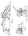
- FIG. 1 a tripartite snow tiller 10 in accordance with the invention is illustrated attached in operational position to a tracked vehicle 11.
- Illustrated tiller 10 comprises three generally equal length tiller sections, a center section 12 and side sections 13 and 14 (See FIG. 1).
- the three tiller sections are secured together end to end to span the snow path to be tilled.
- Tiller sections 12, 13 and 14 each have rotating snow cutter bars 15, 16 and 17 respectively, and frames 18, 19 and 20 respectively.
- Each cutter bar has a multiplicity of radially projecting cutting blades 21.
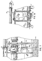
- the side frames 19 and 20 are each secured to opposite ends of the center frame 18 through a pair of aligned hinges 22.
- the hinges axes 23 are both generally horizontal and parallel to the direction of travel (FIGS. 1, 5, 7 and 8).
- the cutter bars 16 and 17 of the side tiller sections are connected to opposite ends of center cutter bar 15 through a universally flexing joint 24.
- the centers of flexing 25 of the universal joints 24 are each located upon one of the horizontal axes 23 of one of the frame hinges 22.
- each of the two side tiller sections 13 and 14 may rotate abouts its respective hinge axis 23 as a unit, both upwardly and downwardly.
- the universal joints 24 permit all the joined together cutter bars to be simultaneously rotated regardless of their condition of alignment or misalignment.
- a pair of hydraulic motors 26 each engage one of the extending drive shafts, not shown, of the side cutter bars 16 and 17 near an outside end of an outside frame 19 or 20 (FIGS. 1-3 and 4).
- Center tiller frame 18 has a square main frame member 27 secured to an oscillation frame 28 through a pair of aligned horizontal pivots 29 oriented laterally to the direction of travel.
- Oscillation frame 28 comprises a lower, square, oscillation tube 30 and an upper reinforcing square tube 31, which carries the aforesaid pivots 29 (FIGS. 1, 2 and 10).
- Oscillation frame 28 is in turn secured through an oscillation bolt 32 through oscillation tube 30 to towing and lift frame 33 of the vehicle 11 (FIG. 11).
- Bolt 32 lies generally horizontally in the direction of tiller travel, and acts as an oscillation spindle. Tiller 10 may twist freely as a unit about bolt 32 in response to irregularities in the surface of the snow.
- beveled frame and tube ends 34 Clearance for relative motion between center frame 18 and end frames 19 and 20 is provided by beveled frame and tube ends 34.
- Flexible fabric cover plates 35 may be secured to span across the gaps between the beveled ends 34 to preclude jamming by rocks or ice (FIGS. 5, 6 and 8).
- the approximately 28 degrees of deflection permitted by beveled ends 34 has been found to be adequate. The maximum deflection is actually limited to that permitted by the reciprocating travel of rams 36 in and out of cylinders 37.
- the rams 36 may be hydraulically fixed in selected positions (FIGS. 1 and 6). Normally, however, rams 36 are left to slide freely in and out of cylinders 34 in response to continuous flexing between the tiller sections during operation.
- Lift frame 33 is joined by lateral pivots 38 to vehicle 11, so that tiller 10 may, if the operator desires, be allowed to move vertically as a unit to further follow uneven snow surfaces. Or, lift frame hydraulic cylinder and rams 39 may be used to hold the tiller firmly on the snow. Also, tiller rotation about laterally horizontal pivots 29 downwardly from normal operating position may sometimes occur (FIGS. 1 and 2). However, tiller 10 is normally held in proper angle of attack with respect to the snow by adjustment of tiller mounted attitude adjusting arm 36′, which bears on pad 37′. Arm 36′ is adjusted in position by positioning of ram 38′ (FIGS. 2 and 11).
- Outside cutter bars 16 and 17 are mounted on frames 19 and 20 respectively by means of piloted flange, self-aligning bearings 39′ on an outside frame end plate 40, and on an inside frame end plate 41 (FIGS. 3, 4, 7 and 9).
- Center cutter bar 15 is supported by one of the universal joints 24 at each end, selected to withstand the high impact upon center cutter bar 15 from irregular, bumpy snow surfaces.
- the reversible hydraulic motors 26 are each mounted on a plate 46 at the outside of each outside frame 19 and 20.
- a power output shaft 47 of motor 26 is joined to a cutter bar drive shaft by a shock absorbing polydisc coupling 48.
- a joint protecting sleeve 49 mounted on each end of center cutter bar 15 extends around each universal joint 24. Radial snow cutting teeth 50 thereon till the snow in the gap between the ends of center and side cutter bars (FIG. 7). Similarly, the outside housings of the polydisc couplings 48 carry snow cutting teeth 51, so that the snow is tilled substantially without interruption the full length of tiller 10 between the motor mounting plates 46.
- Cutter bars 15, 16 and 17 may be rotated either forwardly with blades 21, 50 and 51 cutting the snow oppositely to the direction of travel, or reversely with the snow being cut toward the direction of travel.
- the operator may control the degree for which the snow is conditioned.
- the snow tilled by the blades is propelled to the rear to be collected and compressed by an apron 52, and ultimately smoothed by the grooming bar 53 carrying combing teeth 54 (FIGS. 1, 2, 4 and 7).
- Hydraulic motors 26 are operated simultaneously by hydraulic fluid supply lines, not shown, supplied from a source of pressurized hydraulic fluid provided by a pump carried by vehicle 11. Fluid return lines, not shown, convey used hydraulic fluid back to vehicle 11 for subsequent reuse. Valving, now shown, is provided to reverse the direction of flow of the fluid through both motors 26, to reverse the rotation of the motor drive shafts and the connected snow cutter bars.
- Embodiments other than the illustrated three-section, hydraulic motor powered, version may be employed without departing from the essence of the invention.
- the number of flexibly joined tiller sections need not be limited to the illustrated three. See FIG. 15, schematically indicating a tiller having five tiller sections.
- an embodiment having only two flexibly joined complete tiller sections, although not preferred, would also be within the scope of the invention (FIG. 16).
- a towing bar carries a pair of spaced apart ball joints 56 with extending axles 57 engaged by clevises secured to each of the pair of tiller frames 59.
- the cutter bars could be driven by other types of motors, or even by poser takeoffs or the like from the vehicle.
- tiller mounted motors be on the outside tiller sections.
- a reversible hydraulic motor 26 could be mounted on frame 18 of center tiller section 12, linked by appropriate gearing to the center cutter bar 15 to drive all the cutters. See FIG. 17 showing a motor 26 engaging the two parts of a split cutter bar 15 through a gear box 60. having a pair of power output shafts.
Landscapes
- Life Sciences & Earth Sciences (AREA)
- Engineering & Computer Science (AREA)
- Mechanical Engineering (AREA)
- Soil Sciences (AREA)
- Environmental Sciences (AREA)
- Architecture (AREA)
- Civil Engineering (AREA)
- Structural Engineering (AREA)
- Soil Working Implements (AREA)
- Agricultural Machines (AREA)
- Suspension Of Electric Lines Or Cables (AREA)
Claims (27)
― des moyens de puissance (26) pour faire tourner les barres de coupe par rapport aux axes longitudinaux de celles-ci.
― les moyens de puissance sont montés sur au moins l'un des châssis de section de laboureur.
― les moyens reliant le laboureur au véhicule permettent au laboureur de tourner librement par rapport à un axe longitudinal qui se trouve dans le sens de déplacement du laboureur.
― les moyens de puissance comportent la possibilité de faire tourner les sections de coupe dans un sens prédéterminé.
― des moyens de passage agissant sur la neige labourée par les barre de coupe.
― les moyens de passage comportent une étrave (52) dirigeant la neige et une barre de passage (53).
― les moyens de puissance comportent un moteur hydraulique réversible monté à l'extrémité extérieure du châssis d'au moins une des sections les plus extérieures du laboureur, coopérant avec l'extrémité externe de la barre de coupe de ladite section.
― les moyens de puissance comportent un moteur hydraulique réversible (26) monté à l'extrémité extérieure du châssis d'au moins une des sections les plus extérieures coopérant avec l'extrémité extérieure de la barre de coupe de ladite section.
― les moyens de connexion entra la laboureur et le véhicule comportent en outre un pivot horizontal (29) disposé par rapport à un axe latéral de la direction de déplacement du laboureur, permettant au laboureur de tourner autour de cet axe en fonction de la surface de la neige.
― les moyens de connexion entre le laboureur et le véhicule comportent en outre un pivot horizontal (29) disposé par rapport à un axe latéral à la direction de déplacement du laboureur permettant à ce dernier de tourner par rapport à ce dernier en fonction de la surface de la neige.
― une liaison (36, 37) d'une longueur prédéterminée montée de façon à agir entre les châssis de laboureur à chaque charnière.
― une connexion (36, 37) d'une longueur prédéterminé montée de façon à agir entre les châssis de laboureur à chaque charnière.
― une liaison de longueur prédéterminée (36, 37) montée de façon à agir entre les châssis de laboureur à chaque charnière.
― des moyens formant cylindre hydraulique (37) et poussoir (36).
― des moyens formant cylindre hydraulique (37) et poussoir (36).
― des moyens formant cylindre hydraulique (37) et poussoir (36).
― les barres de coupe de toutes les sections de laboureur sont commandées par un moteur hydraulique (26) monté sur au moins un des châssis des sections de laboureur coopérant avec la barre de coupe de ladite section.
― les barres de coupe de toutes les sections de laboureur sont commandées par un moteur hydraulique (26) monté à l'extrémité extérieure du châssis d'au moins une des sections de laboureur extérieures coopérant avec l'extrémité extérieure de la barre de coupe de ladite section.
― les moyens de connexion entre le laboureur et le véhicule comportent en outre un pivot horizontal (29) disposé selon un axe latéral par rapport à la direction de déplacement du laboureur, permettant à ce dernier de tourner par rapport à celui-ci en fonction de la surface de la neige.
― des moyens formant cylindre hydraulique (37) et poussoir (36) montés pour agir entre les châssis de laboureur à chaque charnière.
― des moyens formant cylindre hydraulique (37) et poussoir (36) montés pour agir entre les châssis de laboureur à chaque charnière.
― des moyens formant cylindre hydraulique et poussoir montés pour agir entre les châssis de laboureur à chaque charnière.
Priority Applications (1)
| Application Number | Priority Date | Filing Date | Title |
|---|---|---|---|
| AT88105519T ATE65814T1 (de) | 1987-04-21 | 1988-04-07 | Rotierendes flexibles schneebearbeitungsgeraet. |
Applications Claiming Priority (2)
| Application Number | Priority Date | Filing Date | Title |
|---|---|---|---|
| US07/040,820 US5067264A (en) | 1987-04-21 | 1987-04-21 | Flexible rotary snow tiller |
| US40820 | 1993-03-31 |
Publications (2)
| Publication Number | Publication Date |
|---|---|
| EP0287897A1 EP0287897A1 (fr) | 1988-10-26 |
| EP0287897B1 true EP0287897B1 (fr) | 1991-07-31 |
Family
ID=21913154
Family Applications (1)
| Application Number | Title | Priority Date | Filing Date |
|---|---|---|---|
| EP88105519A Expired - Lifetime EP0287897B1 (fr) | 1987-04-21 | 1988-04-07 | Appareil tournant flexible pour travailler la neige |
Country Status (6)
| Country | Link |
|---|---|
| US (1) | US5067264A (fr) |
| EP (1) | EP0287897B1 (fr) |
| JP (1) | JPS6429510A (fr) |
| AT (1) | ATE65814T1 (fr) |
| CA (1) | CA1284738C (fr) |
| DE (1) | DE3863959D1 (fr) |
Families Citing this family (24)
| Publication number | Priority date | Publication date | Assignee | Title |
|---|---|---|---|---|
| JPH03183810A (ja) * | 1989-12-13 | 1991-08-09 | Matsuyama Plow Mfg Co Ltd | 整雪装置 |
| JP2510402Y2 (ja) * | 1990-11-20 | 1996-09-11 | 三菱重工業株式会社 | 可変巾スノ―ミル |
| JPH04351667A (ja) * | 1991-05-29 | 1992-12-07 | Shin Etsu Chem Co Ltd | 硬化性樹脂組成物及び電子部品用保護膜 |
| FR2702628B1 (fr) * | 1993-03-19 | 1995-05-05 | Kuhn Sa | Machine agricole de travail du sol de grande largeur s'adaptant mieux au relief du sol. |
| US5632106A (en) * | 1995-08-08 | 1997-05-27 | Lmc Operating Corp. | Tiller with adjustable depth cutter and snow comb entry angle |
| DE29602941U1 (de) * | 1996-02-20 | 1997-06-26 | Kaessbohrer Geländefahrzeug GmbH, 89250 Senden | Pistenfräsvorrichtung |
| DE29603461U1 (de) * | 1996-02-26 | 1997-06-26 | Kässbohrer Geländefahrzeug GmbH, 89250 Senden | Halfpiperäumer |
| FI103824B (fi) * | 1997-02-03 | 1999-09-30 | Mesamo Oy | Laite ja menetelmä lumimaisen materiaalin muokkaamiseksi |
| US6351899B1 (en) * | 1999-05-18 | 2002-03-05 | David Slutzky | Apparatus and method for snow grooming a terrain park or ski area slopes |
| US6948266B1 (en) * | 1999-09-09 | 2005-09-27 | Garry Roger Steedman | Vehicular arm assembly |
| IT1313729B1 (it) * | 1999-09-15 | 2002-09-17 | Leitner Spa | Gruppo di fresatura per la battitura di piste innevate |
| AT500034B1 (de) * | 1999-09-27 | 2006-11-15 | Riepler Bernhard Ing | Auflockerungs- bzw. fräsvorrichtung, damit ausgestattetes fahrzeug und verfahren zur präparierung von pisten |
| WO2001044582A1 (fr) * | 1999-12-17 | 2001-06-21 | Bombardier Inc. | Dameuse munie d'un ensemble fraise a neige a geometrie variable ameliore |
| NL1020080C2 (nl) * | 2002-02-28 | 2003-08-29 | Loen Techniek B V Van | Bodembewerkingsinrichting en verticuteeras. |
| US7540130B2 (en) * | 2006-03-02 | 2009-06-02 | Deere & Company | Height control for a multi-section cutting platform in an agricultural harvesting machine |
| US7614206B2 (en) * | 2007-06-04 | 2009-11-10 | Claas Selbstfahrende Erntemaschinen Gmbh | Winged header apparatus and method for a combine |
| US8635842B2 (en) * | 2009-08-05 | 2014-01-28 | Kevin Markt | Flexible row crop header for an agricultural harvester |
| US9198353B2 (en) * | 2012-09-20 | 2015-12-01 | Deere & Company | Hinged row crop harvesting head |
| US9198355B2 (en) * | 2012-09-20 | 2015-12-01 | Deere & Company | Hinged row crop auger conveyor |
| US9435090B1 (en) * | 2012-12-12 | 2016-09-06 | Tube Shaper, LLC | Groomer for forming lanes in snow |
| ITMI20131925A1 (it) * | 2013-11-20 | 2015-05-21 | Snowgrolic S A R L | Fresa da neve per la preparazione del manto nevoso delle piste da sci |
| BE1022544B1 (nl) * | 2014-12-12 | 2016-05-26 | Cnh Industrial Belgium Nv | Vijzel van graanmaaier voor een oogstmachine |
| CN106884401B (zh) * | 2017-04-07 | 2018-07-03 | 广西玉林悍牛工程机器有限公司 | 压雪车雪犁刮板压实装置 |
| IT201900002017A1 (it) * | 2019-02-12 | 2020-08-12 | Prinoth Spa | Fresa da neve per la preparazione di piste da sci |
Family Cites Families (19)
| Publication number | Priority date | Publication date | Assignee | Title |
|---|---|---|---|---|
| US2538167A (en) * | 1949-02-16 | 1951-01-16 | Theodore G Schmeiser | Earthworking roller unit |
| US3085385A (en) * | 1959-12-16 | 1963-04-16 | Fred L Hansen | Rotary gang mower |
| US3564822A (en) * | 1968-11-21 | 1971-02-23 | Douglass Ind Inc | Full floating mower |
| CH540053A (de) * | 1972-01-10 | 1973-08-15 | Ratrac Ag | Schleppwalze |
| GB1422953A (en) * | 1972-10-06 | 1976-01-28 | Turner Eng Co Coughton Ltd | Mowers |
| CH591202A5 (fr) * | 1975-09-26 | 1977-09-15 | Buetzberger Jean | |
| CA1031621A (fr) * | 1976-01-22 | 1978-05-23 | Kelly A. Krammer | Charrue articulee |
| US4373590A (en) * | 1980-04-25 | 1983-02-15 | The Eversman Mfg. Company | Tilling apparatus |
| US4359831A (en) * | 1980-05-19 | 1982-11-23 | De Lorean Manufacturing Company | Reversibly powered rotary snow tiller |
| SU954011A1 (ru) * | 1981-03-26 | 1982-08-30 | Кировоградский Проектно-Конструкторский Институт По Почвообрабатывающим И Посевным Машинам | Широкозахватна сцепка |
| US4487004A (en) * | 1983-06-03 | 1984-12-11 | Kejr Melvin P | Combine harvester apparatus |
| DE3333941A1 (de) * | 1983-09-20 | 1985-04-04 | Karl Kässbohrer Fahrzeugwerke GmbH, 7900 Ulm | Fraese |
| DE3333942A1 (de) * | 1983-09-20 | 1985-03-28 | Karl Kässbohrer Fahrzeugwerke GmbH, 7900 Ulm | Schneefahrzeug |
| US4538400A (en) * | 1984-06-11 | 1985-09-03 | Allied Products Corporation | Rotary mower having ground supported frames |
| AT382062B (de) * | 1985-02-08 | 1987-01-12 | Ranner Dietrich | Bodenbearbeitungsgeraet |
| US4775014A (en) * | 1986-02-06 | 1988-10-04 | Bombardier-Rotax-Wein Productions- Und Vertriebsgesellschaft M.B.H. | Ground-working implement |
| US4790389A (en) * | 1986-04-22 | 1988-12-13 | Flex-King Corporation | Field cultivator frame with limiting assembly |
| US4878545A (en) * | 1987-06-15 | 1989-11-07 | Victory Equipment (1983) Limited | Agricultural implement with foldable wing |
| US4825958A (en) * | 1988-01-29 | 1989-05-02 | Kelderman Gary L | Hydraulic lock for a flexible tool bar |
-
1987
- 1987-04-21 US US07/040,820 patent/US5067264A/en not_active Expired - Fee Related
- 1987-12-02 CA CA000553295A patent/CA1284738C/fr not_active Expired - Fee Related
-
1988
- 1988-04-07 EP EP88105519A patent/EP0287897B1/fr not_active Expired - Lifetime
- 1988-04-07 DE DE8888105519T patent/DE3863959D1/de not_active Expired - Fee Related
- 1988-04-07 AT AT88105519T patent/ATE65814T1/de not_active IP Right Cessation
- 1988-04-15 JP JP63093276A patent/JPS6429510A/ja active Granted
Also Published As
| Publication number | Publication date |
|---|---|
| CA1284738C (fr) | 1991-06-11 |
| DE3863959D1 (de) | 1991-09-05 |
| JPH0426642B2 (fr) | 1992-05-07 |
| US5067264A (en) | 1991-11-26 |
| EP0287897A1 (fr) | 1988-10-26 |
| JPS6429510A (en) | 1989-01-31 |
| ATE65814T1 (de) | 1991-08-15 |
Similar Documents
| Publication | Publication Date | Title |
|---|---|---|
| EP0287897B1 (fr) | Appareil tournant flexible pour travailler la neige | |
| US5771669A (en) | Method and apparatus for mowing irregular turf areas | |
| US5113958A (en) | Snow travel vehicle | |
| US6116362A (en) | Articulated vehicle | |
| US4359831A (en) | Reversibly powered rotary snow tiller | |
| CA1260719A (fr) | Faucheuse a lames tournantes sur chassis portes au sol | |
| US5199249A (en) | Farm machine adaptable to the contour of the land and having a pivoting housing | |
| CA1187731A (fr) | Dispositif d'attelage et de transport de machines agricoles | |
| US2743567A (en) | Multiple unit contour mower | |
| EP0396548B1 (fr) | Structure de suspension pour vehicule chenille | |
| US4592439A (en) | Multi-purpose, all terrain vehicle | |
| JP3811872B2 (ja) | 2つの調製ユニットを有する作物収穫用農業機械 | |
| AU3292889A (en) | Agricultural reaper or hay making machine | |
| DE10117514B4 (de) | Arbeitsfahrzeug mit einer Nebenabtriebsvorrichtung | |
| US4892154A (en) | Ground-working apparatus with rotary tiller | |
| JP3806465B2 (ja) | 作業車両用の作業装置 | |
| US3884019A (en) | Floatational front mounted mower assembly for power vehicles | |
| US3368292A (en) | Vehicle for conditioning snow slopes, and for transportation thereon | |
| CA2465937C (fr) | Appareil de transfert d'energie articule | |
| US5476276A (en) | Compound steering mechanism with alternate chassis mounts | |
| US4914894A (en) | Short turn implement or vehicle | |
| US5322309A (en) | Oscillation stops for tractors with compound steering mechanism | |
| EP0192917B1 (fr) | Dispositif pour outils agricoles en forme de disque | |
| US3662848A (en) | Hitches for tractor-mounted implements | |
| US6206118B1 (en) | Articulated work vehicle |
Legal Events
| Date | Code | Title | Description |
|---|---|---|---|
| PUAI | Public reference made under article 153(3) epc to a published international application that has entered the european phase |
Free format text: ORIGINAL CODE: 0009012 |
|
| AK | Designated contracting states |
Kind code of ref document: A1 Designated state(s): AT CH DE FR IT LI |
|
| 17P | Request for examination filed |
Effective date: 19890407 |
|
| 17Q | First examination report despatched |
Effective date: 19900626 |
|
| ITF | It: translation for a ep patent filed | ||
| GRAA | (expected) grant |
Free format text: ORIGINAL CODE: 0009210 |
|
| AK | Designated contracting states |
Kind code of ref document: B1 Designated state(s): AT CH DE FR IT LI |
|
| REF | Corresponds to: |
Ref document number: 65814 Country of ref document: AT Date of ref document: 19910815 Kind code of ref document: T |
|
| REF | Corresponds to: |
Ref document number: 3863959 Country of ref document: DE Date of ref document: 19910905 |
|
| ET | Fr: translation filed | ||
| PLBE | No opposition filed within time limit |
Free format text: ORIGINAL CODE: 0009261 |
|
| STAA | Information on the status of an ep patent application or granted ep patent |
Free format text: STATUS: NO OPPOSITION FILED WITHIN TIME LIMIT |
|
| 26N | No opposition filed | ||
| PGFP | Annual fee paid to national office [announced via postgrant information from national office to epo] |
Ref country code: FR Payment date: 20000410 Year of fee payment: 13 |
|
| PGFP | Annual fee paid to national office [announced via postgrant information from national office to epo] |
Ref country code: AT Payment date: 20000418 Year of fee payment: 13 |
|
| PG25 | Lapsed in a contracting state [announced via postgrant information from national office to epo] |
Ref country code: AT Free format text: LAPSE BECAUSE OF NON-PAYMENT OF DUE FEES Effective date: 20010407 |
|
| PG25 | Lapsed in a contracting state [announced via postgrant information from national office to epo] |
Ref country code: FR Free format text: THE PATENT HAS BEEN ANNULLED BY A DECISION OF A NATIONAL AUTHORITY Effective date: 20010430 |
|
| REG | Reference to a national code |
Ref country code: FR Ref legal event code: ST |
|
| PGFP | Annual fee paid to national office [announced via postgrant information from national office to epo] |
Ref country code: CH Payment date: 20020529 Year of fee payment: 15 |
|
| PGFP | Annual fee paid to national office [announced via postgrant information from national office to epo] |
Ref country code: DE Payment date: 20020625 Year of fee payment: 15 |
|
| PG25 | Lapsed in a contracting state [announced via postgrant information from national office to epo] |
Ref country code: LI Free format text: LAPSE BECAUSE OF NON-PAYMENT OF DUE FEES Effective date: 20030430 Ref country code: CH Free format text: LAPSE BECAUSE OF NON-PAYMENT OF DUE FEES Effective date: 20030430 |
|
| PG25 | Lapsed in a contracting state [announced via postgrant information from national office to epo] |
Ref country code: DE Free format text: LAPSE BECAUSE OF NON-PAYMENT OF DUE FEES Effective date: 20031101 |
|
| REG | Reference to a national code |
Ref country code: CH Ref legal event code: PL |
|
| PG25 | Lapsed in a contracting state [announced via postgrant information from national office to epo] |
Ref country code: IT Free format text: LAPSE BECAUSE OF NON-PAYMENT OF DUE FEES;WARNING: LAPSES OF ITALIAN PATENTS WITH EFFECTIVE DATE BEFORE 2007 MAY HAVE OCCURRED AT ANY TIME BEFORE 2007. THE CORRECT EFFECTIVE DATE MAY BE DIFFERENT FROM THE ONE RECORDED. Effective date: 20050407 |