EP0287944A2 - Dispositif d'absorption élastique de chocs - Google Patents
Dispositif d'absorption élastique de chocs Download PDFInfo
- Publication number
- EP0287944A2 EP0287944A2 EP88105915A EP88105915A EP0287944A2 EP 0287944 A2 EP0287944 A2 EP 0287944A2 EP 88105915 A EP88105915 A EP 88105915A EP 88105915 A EP88105915 A EP 88105915A EP 0287944 A2 EP0287944 A2 EP 0287944A2
- Authority
- EP
- European Patent Office
- Prior art keywords
- housing part
- housing parts
- positive locking
- longitudinal groove
- jacket
- Prior art date
- Legal status (The legal status is an assumption and is not a legal conclusion. Google has not performed a legal analysis and makes no representation as to the accuracy of the status listed.)
- Granted
Links
Images
Classifications
-
- B—PERFORMING OPERATIONS; TRANSPORTING
- B61—RAILWAYS
- B61G—COUPLINGS; DRAUGHT AND BUFFING APPLIANCES
- B61G11/00—Buffers
- B61G11/18—Details
-
- B—PERFORMING OPERATIONS; TRANSPORTING
- B61—RAILWAYS
- B61G—COUPLINGS; DRAUGHT AND BUFFING APPLIANCES
- B61G11/00—Buffers
- B61G11/02—Buffers with metal springs
- B61G11/04—Buffers with metal springs with helical springs
Definitions
- the invention relates to a device for resilient absorption of impact forces, in particular sleeve buffers for rail vehicles, which consists of two tubular and telescopically displaceable housing parts braced against each other against the force of a spring, one end of which is designed as a pressure plate supporting the spring, the length of the device free of impact force is fixed by a form-locking anti-rotation device fixedly arranged on one housing part and projecting into a recess in the other housing part, the length of the recess corresponding to at least the maximum displaceability of the two housing parts relative to one another.
- Sleeve buffers in rail vehicles are used to dampen shocks in the longitudinal direction of the vehicle.
- the damping is produced by an elastic pressure system which is arranged in the generally two-part buffer housing and is supported against the bottoms of the tubular and telescopically displaceable housing parts.
- the housing parts are braced against each other and against the force of the printing system.
- the blocks of the housing parts are designed as a pressure plate, the pressure plate of one housing part being firmly connected to the rail vehicle and the pressure plate of the other housing part being designed as a buffer plate.
- a sleeve buffer of the generic type it is known to fix the two housing parts braced against one another by an inserted friction spring by means of a two-part retaining ring which lies in a groove at the open end of the inner housing part and forms a stop for the outer housing part, and thus the installation length and also to determine the preload force of such a sleeve buffer.
- the pressure plate of one housing part either the buffer plate or the pressure plate of the other housing part, is fastened to the corresponding housing part with screws.
- a further known sleeve buffer in which the sleeve and the buffer plate are made from one piece, two semicircular shells of U-shaped cross section serve as holders in the sense described above, one flange of which engages in a groove at the open end of the buffer sleeve and the other flange of which Bypasses the buffer sleeve and rests on a shoulder on the buffer tappet, radially with play to it.
- the two half-shells are braced against each other with two screws, which are arranged in approaches and the mutually facing ends of the half-shells. Also in this known buffer there is no tightness to be required for an optimal spring function due to the radial play described.
- the positive locking rotation is usually formed by a feather key, which in a longitudinal groove of the jacket of the outer housing part is inserted and welded to it and which projects into a longitudinal groove of the jacket of the inner housing part and is longitudinally displaceable in this groove.
- DD-PS 209 780 discloses another sleeve buffer of the generic type, in which the two housing parts of the sleeve buffer are clamped together by means of wedges. These wedges are detachably arranged in the longitudinal slots of the jacket of the outer housing part and protrude into longitudinal slots of the jacket of the inner housing part. The longitudinal slots in the jacket of the inner housing part are designed so that the maximum displaceability of the two housing parts relative to one another is not impaired.
- This sleeve buffer described above thus uses a component for bracing the two housing parts with one another and for preventing the two housing parts from rotating relative to one another.
- a disadvantage of this embodiment is, firstly, the type of fastening of the wedges to the jacket of the outer housing part, which requires cams cast or welded onto the jacket of the outer housing part.
- Another disadvantage is that the longitudinal slot in both the jacket of the outer housing part and the longitudinal slot in the jacket of the inner housing part are open to the sliding surface of the two housing parts and to the inside of the sleeve buffer and thus disadvantageously do not offer any protection against the ingress of moisture and dirt .
- Another disadvantage is the design of the wedge, which requires a complex production method.
- the object of the present invention was to design a device of the generic type so that an economical and simple bracing of the two housing parts of the device with one another and a positive locking rotation of the two housing parts against each other is achieved by using a few and simple standard components and that the sliding surface of the two housing parts of the device and the spring of the device against the one are protected from dirt and moisture.
- this object is achieved in that a longitudinal groove which is limited in length and does not penetrate the jacket is arranged on the outside in the jacket of the inner housing part, that at least one opening is arranged in the jacket of the outer housing part in the region of the longitudinal groove of the inner housing part, and in that in the longitudinal groove a positive locking device is inserted through the opening to the outer housing part.
- the longitudinally displaceable kit of the housing parts in the relaxation direction is adjustable by moving the positive locking device in the longitudinal groove before the positive locking device is fastened to the outer housing part.
- the invention advantageously combines the positive locking rotation of the two housing parts of the device with the device for bracing the two housing parts together to form a unit that is simple and economical. Another advantage is that open breakthroughs are avoided both in the jacket of the outer housing part and in the jacket of the inner housing part. The penetration of moisture and dirt is prevented. Another advantage is that the total length of the device can be adjusted precisely against the spring force.
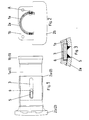
- the device according to the invention consists essentially of the inner housing part 1 that consists of a tubular jacket 1 a and a pressure plate 1 b closing the jacket on one side, and the outer housing part 2, consisting of a tubular jacket 2 a and one closing this one side Pressure plate 2 b, as well as a not shown, in the interior the device located spring.
- the shells 1 a and 2 a of the inner and outer housing parts 1 and 2 are telescopically displaceable.
- at least one opening 5 is provided in the casing 2 a of the outer housing part 2.
- a positive locking device designed as a key 6 is inserted, and welded to the outer housing part 2 within the opening 5 of the casing 2 a.
- the length of the longitudinal groove 3 in the inner housing part 1 between key 6 and the pressure plate 1 b of the inner housing part 1 corresponds at least to the maximum stroke of the device.
- the spring When assembling the device, the spring is inserted into the inner housing part. Then the outer housing part 2 is pushed onto the inner housing part 1 and the feather key 6 is inserted into the longitudinal groove 3. The two housing parts 1 and 2 are then pushed against each other against the force of the spring as far as is necessary to achieve the required overall length of the device. The feather key 6 is then shifted in the longitudinal groove 3 in the direction of the open end of the inner housing part 1 up to the front end of the longitudinal groove 3. The feather key 6 is then welded to the casing 2 a within the opening 5 of the outer housing part. The feather key 6 now acts both as a positive locking rotation of the two housing parts 1 and 2, and as a bracing element of the two housing parts with each other.
Landscapes
- Engineering & Computer Science (AREA)
- Mechanical Engineering (AREA)
- Vibration Dampers (AREA)
- Fluid-Damping Devices (AREA)
- Air Bags (AREA)
- Seal Device For Vehicle (AREA)
- Diaphragms For Electromechanical Transducers (AREA)
- Processing And Handling Of Plastics And Other Materials For Molding In General (AREA)
- Mechanical Treatment Of Semiconductor (AREA)
Priority Applications (1)
| Application Number | Priority Date | Filing Date | Title |
|---|---|---|---|
| AT88105915T ATE68143T1 (de) | 1987-04-18 | 1988-04-14 | Vorrichtung zur federnden aufnahme von stosskraeften. |
Applications Claiming Priority (2)
| Application Number | Priority Date | Filing Date | Title |
|---|---|---|---|
| DE3713206 | 1987-04-18 | ||
| DE19873713206 DE3713206A1 (de) | 1987-04-18 | 1987-04-18 | Vorrichtung zur federnden aufnahme von stosskraeften |
Publications (3)
| Publication Number | Publication Date |
|---|---|
| EP0287944A2 true EP0287944A2 (fr) | 1988-10-26 |
| EP0287944A3 EP0287944A3 (en) | 1989-04-12 |
| EP0287944B1 EP0287944B1 (fr) | 1991-10-09 |
Family
ID=6325911
Family Applications (1)
| Application Number | Title | Priority Date | Filing Date |
|---|---|---|---|
| EP88105915A Expired - Lifetime EP0287944B1 (fr) | 1987-04-18 | 1988-04-14 | Dispositif d'absorption élastique de chocs |
Country Status (7)
| Country | Link |
|---|---|
| EP (1) | EP0287944B1 (fr) |
| AT (1) | ATE68143T1 (fr) |
| DD (1) | DD284648A5 (fr) |
| DE (2) | DE3713206A1 (fr) |
| ES (1) | ES2026960T3 (fr) |
| HU (2) | HUT49529A (fr) |
| PL (1) | PL154529B1 (fr) |
Cited By (2)
| Publication number | Priority date | Publication date | Assignee | Title |
|---|---|---|---|---|
| DE19619213C2 (de) * | 1996-05-13 | 2000-03-09 | Eisenbahntech Halberstadt Gmbh | Puffer, insbesondere Hülsenpuffer für Schienenfahrzeuge |
| CN113070346A (zh) * | 2021-04-26 | 2021-07-06 | 浙江龙盛薄板有限公司 | 一种油箱缓冲装置 |
Family Cites Families (4)
| Publication number | Priority date | Publication date | Assignee | Title |
|---|---|---|---|---|
| DE462538C (de) * | 1927-03-06 | 1928-07-12 | Friedrich Reckel | Eisenbahnhuelsenpuffer |
| FR1197420A (fr) * | 1957-08-30 | 1959-12-01 | Garringtons Ltd | Perfectionnements apportés aux mécanismes de tampon et d'attelage pour chemin de fer et analogues |
| US3253718A (en) * | 1964-08-10 | 1966-05-31 | Miner Inc W H | Buffer |
| DE2619469C2 (de) * | 1976-05-03 | 1982-05-19 | Ringfeder Gmbh, 4150 Krefeld | Hülsenpuffer zur federnden Aufnahme von Stoßkräften, insbesondere für Schienenfahrzeuge |
-
1987
- 1987-04-18 DE DE19873713206 patent/DE3713206A1/de not_active Withdrawn
-
1988
- 1988-04-14 AT AT88105915T patent/ATE68143T1/de not_active IP Right Cessation
- 1988-04-14 DE DE8888105915T patent/DE3865345D1/de not_active Expired - Fee Related
- 1988-04-14 EP EP88105915A patent/EP0287944B1/fr not_active Expired - Lifetime
- 1988-04-14 ES ES198888105915T patent/ES2026960T3/es not_active Expired - Lifetime
- 1988-04-15 DD DD88314796A patent/DD284648A5/de not_active IP Right Cessation
- 1988-04-15 HU HU881865A patent/HUT49529A/hu unknown
- 1988-04-15 HU HU881965A patent/HU201271B/hu not_active IP Right Cessation
- 1988-04-18 PL PL1988271906A patent/PL154529B1/pl unknown
Cited By (2)
| Publication number | Priority date | Publication date | Assignee | Title |
|---|---|---|---|---|
| DE19619213C2 (de) * | 1996-05-13 | 2000-03-09 | Eisenbahntech Halberstadt Gmbh | Puffer, insbesondere Hülsenpuffer für Schienenfahrzeuge |
| CN113070346A (zh) * | 2021-04-26 | 2021-07-06 | 浙江龙盛薄板有限公司 | 一种油箱缓冲装置 |
Also Published As
| Publication number | Publication date |
|---|---|
| EP0287944B1 (fr) | 1991-10-09 |
| ATE68143T1 (de) | 1991-10-15 |
| EP0287944A3 (en) | 1989-04-12 |
| ES2026960T3 (es) | 1992-05-16 |
| HU201271B (en) | 1990-10-28 |
| DE3865345D1 (de) | 1991-11-14 |
| PL271906A1 (en) | 1989-01-23 |
| DD284648A5 (de) | 1990-11-21 |
| DE3713206A1 (de) | 1988-10-27 |
| HUT49529A (en) | 1989-10-30 |
| PL154529B1 (en) | 1991-08-30 |
Similar Documents
| Publication | Publication Date | Title |
|---|---|---|
| EP1182104B1 (fr) | Dispositif de verrouillage pour la colonne de direction d'un véhicule | |
| DE3030519A1 (de) | Aussenliegender ziehgriff, insbesondere fuer kraftfahrzeugtueren | |
| DE9420230U1 (de) | Gelenklagerung für Schienenfahrzeuge | |
| EP0740085A1 (fr) | Frein à disque | |
| EP1380807A1 (fr) | Dispositif de montage d'une lunette de visée pour arme à feu | |
| DE2141366A1 (de) | Werkzeug zur Montage bzw. Demontage von Schraubenfeder-Stoßdämpfern und Verfahren unter Verwendung dieses Werkzeuges | |
| DE102008055518A1 (de) | Verbindungsstück | |
| EP0287944B1 (fr) | Dispositif d'absorption élastique de chocs | |
| DE2522600C2 (de) | Anordnung für einen Lenkstockschalter für Kraftfahrzeuge | |
| DE2619469A1 (de) | Vorrichtung zur federnden aufnahme von stosskraeften | |
| DE10133708C1 (de) | Befestigungssystem für eine geteilte Kraftfahrzeug-Fondlehne | |
| DE19945164A1 (de) | Lenksäulenbaugruppe | |
| DE9105358U1 (de) | Schwimmsattelbremse und Bolzen für eine solche | |
| DE10004178A1 (de) | Bolzenführungseinrichtung für eine Schwimmsattel-Scheibenbremse | |
| EP0156793B1 (fr) | Moyens de fixation d'une poignée de porte sur une serrure | |
| DE9406986U1 (de) | Sicherheitsschildanordnung | |
| DE8710838U1 (de) | Vorrichtung zur federnden Aufnahme von Stoßkräften | |
| DE9314961U1 (de) | Anordnung zum Befestigen von Haltestangen | |
| EP1410971A2 (fr) | Colonne de direction | |
| EP0414672B1 (fr) | Unite lineaire pour la manutention d'equipement et analogue, pour utilisation dans l'industrie manufacturiere | |
| DE3416151A1 (de) | Abschliessbarer fenstergriff | |
| DE4436259C1 (de) | Türaußengriff für ein Kraftfahrzeug | |
| DE19529729C2 (de) | Stoßdämpfer für den Sattel eines Zweirads | |
| DE4222479C2 (de) | Kraftfahrzeuglenkung, enthaltend eine Lenksäule und ein Lenkgetriebe | |
| DE4202903C2 (de) | Steckverbindung an Maschinenteilen |
Legal Events
| Date | Code | Title | Description |
|---|---|---|---|
| PUAI | Public reference made under article 153(3) epc to a published international application that has entered the european phase |
Free format text: ORIGINAL CODE: 0009012 |
|
| 17P | Request for examination filed |
Effective date: 19880428 |
|
| AK | Designated contracting states |
Kind code of ref document: A2 Designated state(s): AT BE CH DE ES FR GB IT LI LU NL SE |
|
| PUAL | Search report despatched |
Free format text: ORIGINAL CODE: 0009013 |
|
| AK | Designated contracting states |
Kind code of ref document: A3 Designated state(s): AT BE CH DE ES FR GB IT LI LU NL SE |
|
| 17Q | First examination report despatched |
Effective date: 19900807 |
|
| GRAA | (expected) grant |
Free format text: ORIGINAL CODE: 0009210 |
|
| AK | Designated contracting states |
Kind code of ref document: B1 Designated state(s): AT BE CH DE ES FR GB IT LI LU NL SE |
|
| REF | Corresponds to: |
Ref document number: 68143 Country of ref document: AT Date of ref document: 19911015 Kind code of ref document: T |
|
| REF | Corresponds to: |
Ref document number: 3865345 Country of ref document: DE Date of ref document: 19911114 |
|
| GBT | Gb: translation of ep patent filed (gb section 77(6)(a)/1977) | ||
| ITF | It: translation for a ep patent filed | ||
| ET | Fr: translation filed | ||
| REG | Reference to a national code |
Ref country code: ES Ref legal event code: FG2A Ref document number: 2026960 Country of ref document: ES Kind code of ref document: T3 |
|
| PLBE | No opposition filed within time limit |
Free format text: ORIGINAL CODE: 0009261 |
|
| STAA | Information on the status of an ep patent application or granted ep patent |
Free format text: STATUS: NO OPPOSITION FILED WITHIN TIME LIMIT |
|
| 26N | No opposition filed | ||
| EPTA | Lu: last paid annual fee | ||
| EAL | Se: european patent in force in sweden |
Ref document number: 88105915.8 |
|
| PGFP | Annual fee paid to national office [announced via postgrant information from national office to epo] |
Ref country code: GB Payment date: 19950220 Year of fee payment: 8 |
|
| PGFP | Annual fee paid to national office [announced via postgrant information from national office to epo] |
Ref country code: CH Payment date: 19950223 Year of fee payment: 8 |
|
| PGFP | Annual fee paid to national office [announced via postgrant information from national office to epo] |
Ref country code: SE Payment date: 19950224 Year of fee payment: 8 Ref country code: AT Payment date: 19950224 Year of fee payment: 8 |
|
| PGFP | Annual fee paid to national office [announced via postgrant information from national office to epo] |
Ref country code: LU Payment date: 19950301 Year of fee payment: 8 |
|
| PGFP | Annual fee paid to national office [announced via postgrant information from national office to epo] |
Ref country code: FR Payment date: 19950310 Year of fee payment: 8 |
|
| PGFP | Annual fee paid to national office [announced via postgrant information from national office to epo] |
Ref country code: BE Payment date: 19950322 Year of fee payment: 8 |
|
| PGFP | Annual fee paid to national office [announced via postgrant information from national office to epo] |
Ref country code: ES Payment date: 19950404 Year of fee payment: 8 |
|
| PGFP | Annual fee paid to national office [announced via postgrant information from national office to epo] |
Ref country code: NL Payment date: 19950430 Year of fee payment: 8 |
|
| PG25 | Lapsed in a contracting state [announced via postgrant information from national office to epo] |
Ref country code: LU Free format text: LAPSE BECAUSE OF NON-PAYMENT OF DUE FEES Effective date: 19960414 Ref country code: GB Effective date: 19960414 Ref country code: AT Effective date: 19960414 |
|
| PG25 | Lapsed in a contracting state [announced via postgrant information from national office to epo] |
Ref country code: SE Effective date: 19960415 Ref country code: ES Free format text: LAPSE BECAUSE OF NON-PAYMENT OF DUE FEES Effective date: 19960415 |
|
| PG25 | Lapsed in a contracting state [announced via postgrant information from national office to epo] |
Ref country code: LI Effective date: 19960430 Ref country code: CH Effective date: 19960430 Ref country code: BE Effective date: 19960430 |
|
| PGFP | Annual fee paid to national office [announced via postgrant information from national office to epo] |
Ref country code: DE Payment date: 19961025 Year of fee payment: 9 |
|
| BERE | Be: lapsed |
Owner name: WAGGON UNION G.M.B.H. Effective date: 19960430 |
|
| PG25 | Lapsed in a contracting state [announced via postgrant information from national office to epo] |
Ref country code: NL Effective date: 19961101 |
|
| GBPC | Gb: european patent ceased through non-payment of renewal fee |
Effective date: 19960414 |
|
| REG | Reference to a national code |
Ref country code: CH Ref legal event code: PL |
|
| PG25 | Lapsed in a contracting state [announced via postgrant information from national office to epo] |
Ref country code: FR Effective date: 19961227 |
|
| NLV4 | Nl: lapsed or anulled due to non-payment of the annual fee |
Effective date: 19961101 |
|
| EUG | Se: european patent has lapsed |
Ref document number: 88105915.8 |
|
| REG | Reference to a national code |
Ref country code: FR Ref legal event code: ST |
|
| PG25 | Lapsed in a contracting state [announced via postgrant information from national office to epo] |
Ref country code: DE Free format text: LAPSE BECAUSE OF NON-PAYMENT OF DUE FEES Effective date: 19980101 |
|
| REG | Reference to a national code |
Ref country code: ES Ref legal event code: FD2A Effective date: 19990405 |
|
| PG25 | Lapsed in a contracting state [announced via postgrant information from national office to epo] |
Ref country code: IT Free format text: LAPSE BECAUSE OF NON-PAYMENT OF DUE FEES;WARNING: LAPSES OF ITALIAN PATENTS WITH EFFECTIVE DATE BEFORE 2007 MAY HAVE OCCURRED AT ANY TIME BEFORE 2007. THE CORRECT EFFECTIVE DATE MAY BE DIFFERENT FROM THE ONE RECORDED. Effective date: 20050414 |