EP0288034A2 - Flugsteuersystem mit Verwendung von drei Steuervorrichtungen zur Betätigung eines Doppelantriebs - Google Patents
Flugsteuersystem mit Verwendung von drei Steuervorrichtungen zur Betätigung eines Doppelantriebs Download PDFInfo
- Publication number
- EP0288034A2 EP0288034A2 EP88106321A EP88106321A EP0288034A2 EP 0288034 A2 EP0288034 A2 EP 0288034A2 EP 88106321 A EP88106321 A EP 88106321A EP 88106321 A EP88106321 A EP 88106321A EP 0288034 A2 EP0288034 A2 EP 0288034A2
- Authority
- EP
- European Patent Office
- Prior art keywords
- valve
- flight control
- signal
- electrohydraulic
- signals
- Prior art date
- Legal status (The legal status is an assumption and is not a legal conclusion. Google has not performed a legal analysis and makes no representation as to the accuracy of the status listed.)
- Withdrawn
Links
Images



Classifications
-
- B—PERFORMING OPERATIONS; TRANSPORTING
- B64—AIRCRAFT; AVIATION; COSMONAUTICS
- B64C—AEROPLANES; HELICOPTERS
- B64C13/00—Control systems or transmitting systems for actuating flying-control surfaces, lift-increasing flaps, air brakes, or spoilers
- B64C13/24—Transmitting means
- B64C13/38—Transmitting means with power amplification
- B64C13/50—Transmitting means with power amplification using electrical energy
- B64C13/505—Transmitting means with power amplification using electrical energy having duplication or stand-by provisions
-
- G—PHYSICS
- G05—CONTROLLING; REGULATING
- G05D—SYSTEMS FOR CONTROLLING OR REGULATING NON-ELECTRIC VARIABLES
- G05D1/00—Control of position, course, altitude or attitude of land, water, air or space vehicles, e.g. using automatic pilots
- G05D1/0055—Control of position, course, altitude or attitude of land, water, air or space vehicles, e.g. using automatic pilots with safety arrangements
- G05D1/0077—Control of position, course, altitude or attitude of land, water, air or space vehicles, e.g. using automatic pilots with safety arrangements using redundant signals or controls
Definitions
- This invention relates to aircraft flight control systems, and more particularly, to a redundant control system for hydraulic flight control actuators.
- Aircraft flight control surfaces such as ailerons, elevators and rudders, are usually operated by hydraulic actuators, generally consisting of a hydraulic cylinder enclosing a piston mounted on an actuator rod.
- the hydraulic fluid applied to the hydraulic actuator is generally controlled by an electrohydraulic servovalve having at least one control coil receiving a control signal from a controller.
- a linear variable differential transformer may be coupled to the actuator rod.
- the linear differential transformer provides a feedback signal to the controller which indicates the position of the actuating rod.
- a linear variable differential transformer may be mechanically coupled to the electrohydraulic servovalve stem to provide a monitor signal to the controller which indicates the position of the valve stem and hence the rate of actuator movement.
- the typical approach to implementing a "fail safe" flight control system is to use redundant components in the system.
- a flight control system utilizing redundant components can continue to function after the malfunction of a single component.
- the number of redundant components can be increased to even more than two or even three identical components.
- the reliability of a flight control system can reach any desired value by merely increasing the number of redundant components.
- the number of redundant components that can be used is limited by several factors. First, it is normally desirable to minimize the weight of aircraft employing flight control systems. The extra weight resulting from the use of redundant components unduly increases the weight of aircraft. Second, a greater number of redundant components increases the probability that at least one of the components will fail, thus producing an unacceptable mean time between failure for the entire system. Finally, the use of redundant components can easily multiply by several times the cost of the flight control systems. Therefore, it is important that optimum redundancy be achieved with a minimum number of components.
- a hydraulic flight control system comprising: a tandem hydraulic actuator having an actuating rod connected to a pair of pistons mounted in respective first and second cylinders; first and second electrohydraulic servovalves controlling the flow of hydraulic fluid into and out of the first and second hydraulic cylinders, respectively, each of the electrohydraulic servovalves being controlled by a pair of actuating coils; first, second and third controller means receiving a flight control signal, the first controller means having a control channel that is capable of providing an output to one actuating coil of the first electrohydraulic servovalve for operating the first electrohydraulic servovalve, the second controller means having a control channel that is capable of providing an output to one actuating coil of the second electrohydraulic servovalve for operating the second electrohydraulic servovalve, the third control having first and second control channels that are capable of providing respective outputs to the other actuating coils of the first and second electrohydraulic servovalves; and
- the invention provides for a flight control system receiving input flight control signals from a flight control computer to manipulate a flight control surface.
- a dual hydraulic actuator is used to manipulate the flight control surface.
- the dual actuator has an actuating rod connected to the flight control surface, and a pair of pistons are mounted on the actuating rod in respective first and second cylinders.
- the flow of hydraulic fluid into and out of the first and second cylinders in controlled by the first and second electrohydraulic servovalves, respectively.
- the electrohydraulic servovalves are, in turn, operated by the respective signals applied to a pair of actuating coils.
- the system includes three controllers that receive the flight control signal and apply respective output signals to the four coils of the two electrohydraulic servovalves.
- the first controller is connected to the one coil of the first electrohydraulic servovalve
- the second controller is connected to one coil of the second electrohydraulic servovalve
- the third controller has two outputs that are connected to the other coils of the first and second electrohydraulic servovalves.
- controllers The operation of the controllers, electrohydraulic servovalves and actuator are monitored, and the controllers selectively enabled so that each of the electrohydraulic servovalves is operated by only one controller at a time.
- the other controller connected to the electrohydraulic servovalve is enabled.
- Position sensors are coupled to the actuating rod to generate actuating rod position signals.
- the actuating rod position signals are used as negative feedback to the controllers to allow the controllers to generate the signals applied to the electrohydraulic servovalve actuating coils as a function of the difference between the flight control signal and each actuating rod position signal.
- the electrohydraulic servovalves preferably include valve position sensors providing valve-monitoring signals which indicate the operation of the valves.
- the valve monitor signals are compared to reference signals that correspond to the expected values of the valve reference signal in response to the current flight control signal.
- the reference signals are generated by model channels in the controllers that have a transfer characteristic that simulates the characteristic of the electrohydraulic servovalves' responses to the control signals.
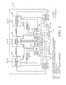
- the inventive flight control utilizes a dual actuator 12 having a pair of hydraulic cylinders 14, 16 containing respective pistons 18, 20 mounted on a common actuating rod 22.
- the actuating rod 22 is coupled in a conventional manner to a flight control surface, such as an aileron, elevator or rudder.
- a flight control surface such as an aileron, elevator or rudder.
- the flow of hydraulic fluid into and out of each cylinder 14, 16 of the dual actuator 12 is controlled by dual-coil electrohydraulic servovalves 30, 32.
- Each of the electrohydraulic servovalves 30, 32 is driven by its own conventional hydraulic system so that a hydraulic system malfunction will affect only one-half of the dual actuator 12.
- the electrohydraulic servovalves 30, 32 include a control coil (not shown) that receives an electrical signal. The electrical signal displaces a valve spool, thereby allowing hydraulic fluid to flow into and out of the cylinders 14, 16.
- the electrical signals applied to the control coils of the electrohydraulic servovalves thus control the rate at which hydraulic fluid flows into or out of the hydraulic cylinders 14, 16, which, in turn, controls the rate of actuating rod movement 22.
- the position of the valve stem in each electrohydraulic servovalve 30, 32 is monitored by respective pairs of conventional linear variable differential transformers 34, 36 and 38, 40.
- the linear variable differential transformers (“LVDTs") generate electrical signals that are proportional to the position of their respective valve spool. Consequently, the signals generated by the LVDTs are proportional to the rate at which the hydraulic fluid is flowing into and out of the cylinders 14, 16, which is, in turn, proportional to the rate of movement of the actuating rod 22.
- Conventional LVDTs 42, 44, 46, 48 are coupled to the actuating rod 22 to provide signals indicative of the position of the actuating rod. As explained in greater detail below, the outputs of the LVDTs 42, 44, 46, 48 are used as feedback signals to compare with the flight control signals from conventional flight control computers to generate the signals applied to the actuating coils of the electrohydraulic servovalves 30, 32.
- the electrohydraulic servovalves 30, 32 are, in normal operation, driven by a primary controller 50 on the basis of a flight control signal from a respective flight control computer FCC "B."
- the primary controller 50 has a CH 1B output that drives one control coil of the electrohydraulic servovalve 30 and a CH 2B output that drives one control coil of the electrohydraulic servovalve 32.
- Negative feedback for the electrohydraulic servovalve 30 is provided by LVDT "B1" 44, while negative feedback for electrohydraulic servovalve 32 is provided to the primary controller 50 by the LVDT "B2.”
- valve monitor signals generated by respective LVDTs 36, 38 are applied to the primary controller 50 so that the primary controller 50 can monitor the operation of the electrohydraulic servovalves 30, 32.
- the valve monitor signals from the LVDTs 36, 38 are compared to each other and to respective model signals that correspond to the expected valve monitor signals for a given flight control signal.
- the output signal from the primary controller 50 for the affected electrohydraulic servovalve 30, 32 terminates, and a discrete signal is applied to a secondary controller 52, 54 for the affected electrohydraulic servovalve 30, 32. Thereafter, the electrohydraulic servovalve 30, 32 is driven by a secondary controller 52, 54 which then applies a control signal to a separate actuating coil in each of the electrohydraulic servovalves 30, 32.
- the primary controller 50 will deactivate channel CH 1B and send a DISCRETE signal to the secondary controller "A" 52. Thereafter, secondary controller "A" 52 will drive the electrohydraulic servovalve 30 through its own actuating coil. It should be emphasized that each of the electrohydraulic servovalves 30, 32 receives a signal from only controller 50 or 52, 50 or 54, respectively, at a time.
- a conventional bypass valve 60 or 62 is actuated by the controllers to allow hydraulic fluid to freely flow from one end of each cylinder 14 or 16 to the other.
- the primary controller sends a bypass signal to the bypass valve 60.
- the bypass valve 60 does not become operative until a second bypass signal is received from the secondary controller 52.
- the secondary controller 52 applies a second bypass signal to the bypass valve 60 at which point the bypass valve 60 moves to the bypass position.
- the operation of the bypass valve 62 for the hydraulic cylinder 16 is controlled by the primary controller 50 and the secondary controller 54 in the same manner.
- bypass valves 60, 62 are spring-biased to their bypass position and held in a non-bypass position by hydraulic pressure and by the outputs from the primary controller 50 and the secondary controllers 52, 54.
- the bypass valves 60, 62 automatically move to their bypass position.
- the bypass valves 60, 62 it is possible for the bypass valves 60, 62 to fail in their non-bypass position, thereby hydraulically locking the actuating rod 22, this condition is highly unlikely.
- the failure detection logic of the primary controller 50 recognizes the malfunction and switches off the operation of the failed channel CH 1B and activates the secondary controller 52 by sending out a DISCRETE signal to the secondary controller 52.
- the secondary controller "A" 52 then operates in the active control mode, and the channel CH 1B of the primary controller “B” 50 is deactivated so that the electrohydraulic servovalve 30 is thereafter controlled by the secondary controller 52 CH 1A channel through the coil of the electrohydraulic servovalve 30 connected to the secondary controller 52.
- the dual actuator 12 remains fully operational.
- the primary controller 50 will switch the secondary controller 54 to its active mode, as described above with reference to secondary controller 52. Thereafter, the electrohydraulic servovalve 32 will be driven by the secondary controller 54 through the actuating coil of the electrohydraulic servovalve 32 connected to the secondary controller 54.
- the dual actuator 12 will remain fully operational.
- bypass valve 60 then shifts to its bypass position, thereby allowing, in effect, hydraulic fluid to flow freely around the piston 18.
- the electrohydraulic servovalve 30, of course becomes inoperative because the CH 1B channel of the primary controller 50 and the secondary controller 52 have both malfunctioned. Nevertheless, the flight control system remains operative, although the force that can be generated by the actuator 12 is reduced by about fifty percent.
- bypass valves 60, 62 There are two possible failure modes for the bypass valves 60, 62.
- the bypass valves 60, 62 can fail either by erroneously shifting to a bypass mode or by not shifting to a bypass mode when commanded.
- the unwanted shifting of the bypass valve 60 or 62 to a bypass mode during operation of the actuator 12 will result in loss of one actuator operation. This failure reduces the force output capability of the dual actuator 12, and the redundancy of the system is reduced.
- a more serious problem is that of the bypass valves 60, 62 not shifting into the bypass mode after receiving two bypass commands from the controllers 52, 50 or 50, 54 controlling the valves 60, 62, respectively.
- This failure can result in hydraulic locking, thus making the dual actuator 12 inoperable. For this reason, the operation of the bypass valves 60, 62 should be periodically checked. However, since the bypass valves 60, 62 are biased to their bypass mode by a spring, a failure of the bypass valves 60, 62 to bypass when commanded is unlikely.
- the worst case of failure mode occurs when a single component in each of three different controller chains occurs (e.g., both channels of primary controller 50 and secondary controller 52), in which case the actuator 12 continues to be operated by a single controller 54, a single electrohydraulic servovalve 32 and one-half of the dual actuator 12.
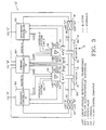
- the flight control system illustrated in Figure 2 is very similar to the flight control system illustrated in Figure 1, since it employs most of the same components operating in the same manner. Consequently, identical components operating in the same manner have been given identical reference numerals.
- the flight control system as illustrated in Figure 2 utilizes secondary controllers 70, 72, including voting and switching logic that is similar to the voting and switching logic in the secondary controller 52 and 54 in the embodiment of Figure 1. Further, the secondary controller is capable of generating a discrete signal which is applied to the primary controller 74.
- the secondary controllers 70, 72 can thus detect disagreement between the valve monitor signals applied to the secondary controller 70, 72 and internally generated valve modeling signals. If the valve monitor signals do not match these other signals, the secondary controller 70, 72 can send a DISCRETE signal to the primary controller 74. Consequently, in the event of a malfunction of any controller or any input upstream to any controller, the failed controller channel can be voted out through cross-channel voting.
- both electrohydraulic servovalves 30 and 32 receive control inputs from CH 1B and CH 2B, respectively, of the primary controller 74, and both secondary controllers 70 and 72 monitor the actuator operation.
- the conventional logic circuitry forming part of the primary controller "B” 74 recognizes that the signals, of CH 1B, CH 2B and CH 2C will all match each other and that only CH 1A failed, which is the signal created in secondary controller "A.” Then, primary controller "B” 74 provides a discrete signal to secondary controller "A” 70 to stop the operation of controller "A” 70 until the failure condition exists in controller "A” 70 or upstream of this controller.
- a second failure mode involves a failure in the flight control computer "C," upstream from secondary controller 72.
- This failure mode is treated in the same manner as the preceding example, except that secondary controller 72 is voted out in the same manner that secondary controller 70 was voted out in the preceding example.
- cross-channel voting allows a failure upstream from controller 70 or controller 72 to be detected without disturbing the actuator operation, which has remained under the control of primary controller 74.
- the flight control computer "B" which drives primary controller 74, fails, so the monitoring signals from LVDT 1A 34 and LVDT 2C 40 will not match the model signals in secondary controllers 70 and 72. Therefore, the failure detection logic of each secondary controller, controllers 70 and 72, provides a discrete signal to primary controller 74, which indicates that CH 1A and CH 2C disagree with CH 1B and CH 2B. Two secondary controllers, 70 and 72, then vote out primary controller 74, even though the valve model signals in primary controller 74 match their respective valve monitor signals from the LVDT 1B 36 and LVDT 2B 38.
- Dual actuator 12 remains fully operational with primary controller 74 and one secondary controller. Simultaneous malfunctions of both DISCRETE signals from each secondary controller are needed to shut down primary controller 74, but dual actuator 12 remains fully operational.
- the DISCRETE signals should be active low so that a complete failure in any controller 70, 72 or 74 will cause the controller to generate no output to its associated electrohydraulic servovalve coil and a DISCRETE signal to activate the standby controller. Using a DISCRETE signal that is active low also prevents both coils of the same electrohydraulic servovalve from being active at the same time.
- failure detection is accomplished in the secondary controllers 70, 72 by comparing their internal valve model signals to the valve monitor signals from the LVDT's 34, 40, respectively. In the event that these signals differ by more than a predetermined value, both secondary controllers 70, 72 would send DISCRETE signals to the primary controller 74 to cause the primary controller 74 to be deactivated. At the same time, the secondary controller 70 drives the electrohydraulic servovalve 30 through its internal actuating coil. Thus, in the event of a malfunction in the primary controller 74 that prevents it from recognizing a malfunction, this function can be performed by the secondary controllers 70, 72.
- the embodiment of the inventive flight control system of Figure 3 like the embodiment of Figure 2, employs a number of components used in the embodiment of Figure 1 which operate in the same manner. Consequently, these components have been given the same reference numerals.
- the embodiment illustrated in Figure 3 differs from the embodiment shown in Figure 1 in that it uses a pair of primary controllers 80, 82 to drive the electrohydraulic servovalves 30, 32, respectively, in the normal operating mode.
- the primary controller 80 outputs a control signal to its respective actuating coil of electrohydraulic servovalve 30 through channel 1A, while primary controller 82 outputs a control signal to the actuating coil of electrohydraulic servovalve 32 through channel 2C.
- a secondary controller 84 has two channels, 1B and 2B, connected to respective actuating coils of the electrohydraulic servovalves 30, 32, respectively.
- the primary controller 80, 82 for the affected channel then outputs a DISCRETE signal to the secondary controller 84, deactivates its control channel 1A or 2C, and applies a bypass signal to the bypass valve 60 or 62. Thereafter, a channel of the secondary controller 84 controls the electrohydraulic servovalve 30 or 32.
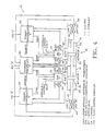
- the embodiment of Figure 4 like the previous embodiments, also utilizes a large number of components that are common to the earlier embodiments and are thus given identical reference numerals.
- the embodiment of Figure 4 differs from the embodiment of Figure 2 in that it, like the embodiment of Figure 3, utilizes a pair of primary controllers 90, 92 and a single secondary controller 94.
- the electrohydraulic servovalves 30, 32 are driven by the primary controllers 90, 92.
- control is transferred to the secondary controller 94.
- the embodiment of Figure 4 utilizes a secondary controller 94 that is capable of detecting a malfunction in either of the primary controllers 90, 92 and then causing the primary controllers 90, 92 to transfer control to the proper channel of the secondary controller 94.
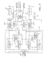
- the primary controller 50 used in the embodiment of Figure 1 is illustrated in greater detail in Figure 5.
- the circuitry illustrated in Figure 5 also includes the components of the flight control system illustrated in Figure 1 that are connected to the primary controller 50, but it does not include the secondary controllers 52, 54 that are also connected to these components.
- the primary controller 50 may be implemented in a variety of forms without departing from the scope of this invention. More specifically, the components illustrated in Figure 5 can be analog circuitry or digital circuitry. Moreover, the components can be implemented in whole or in part by a microprocessor which can easily be programmed by one skilled in the art to implement the components illustrated in Figure 5.
- the primary controller 50 preferably will utilize two microprocessors so that a malfunction in one microprocessor can be detected by the other microprocessor in order to discontinue operation of the primary controller 50 and generate DISCRETE signals to the secondary controllers 52, 54. Regardless of the manner of implementing the components illustrated in Figure 5, they can easily be implemented by one skilled in the art using well-known circuit design or programming techniques.
- the primary controller 50 includes a pair of active channels 100, 102 that generate an electrohydraulic servovalve control signal as a function of the difference between a flight control signal generated by an upstream flight control computer 104 and position feedback signals output by respective LVDTs 44, 48.
- the flight control signal from the flight control computer 104 and the actuator feedback signals from the LVDTs 44, 48 are also applied to respective standby channels 106, 108.
- the outputs of the standby channels are applied to respective model circuits 110, 112 of conventional design which have a transfer function selected to output a valve model signal that is identical or corresponds to the expected valve feedback signals from the LVDTs 36, 38.
- the expected effect of the flight control signal on each electrohydraulic servovalve 30, 32 is known and is simulated by the model circuits 110, 112.
- the valve monitor signals that should be generated by the LVDTs 36, 38 for a given response of the electrohydraulic servovalves 30, 32 are also known. Consequently, the expected valve monitor signals from the LVDTs as a function of the flight control signals are also known.
- the transfer functions of the model circuits 110, 112 are selected so that the valve model signals generated by the model circuits 110, 112 will be identical or correspond to these expected valve monitor signals.
- the valve feedback signals from the LVDTs and the model signals from the model circuits 110, 112 are then applied to a monitor and control logic circuit 114.
- the monitor and control logic circuit 114 compares each of the valve feedback signals from the LVDTs 36, 38 to each other and to the valve model signals from the model circuits 110, 112. In the event that one of the valve feedback signals does not correspond to the other valve feedback signal or to the valve model signals, the monitor and control logic 114 actuates a transfer signal switch 116, 118 for the affected channel, thereby using the standby channel 106 or 108 to generate the control signal for the electrohydraulic servovalves 30, 32.
- the monitor and control logic 114 determines that the valve monitor signal from the LVDT 36 does not correspond to the valve monitor signal from the LVDT 38 or to the model signals from the model circuits 110, 112, it actuates transfer switch 116 so that the output of the standby channel 106 is then applied to the electrohydraulic servovalve 30. If the improper valve monitor signal from LVDT 36 was a result of a malfunction in the active channel circuit 100, the primary controller 50 will once again be operative in driving the electrohydraulic servovalve 30.
- An incorrect valve monitor signal from the LVDT 36 may be due to a malfunction in a component other than the active channel circuit 100.
- the malfunction may be due to a malfunction in the actuating coil driving the electrohydraulic servovalve 30.
- actuating the transfer signal switch 116 to allow the standby channel 106 to generate the control signal will not correct the malfunction.
- the monitor and control logic 114 will continue to recognize the malfunction and thus apply a DISCRETE "A" signal to the secondary controller 52 to transfer control of the electrohydraulic servovalve 30 to the secondary controller 52.
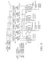
- the monitor and control logic 114 used in the primary controller 50 ( Figure 5) is illustrated in greater detail in Figure 6.
- the monitor and control logic circuit 114 receives valve monitor signals 1B and 2B from the LVDTs 36, 38, respectively. It also receives valve model signals 1 BM and 2 BM from the model circuits 110, 112.
- the 1B valve monitor signal is first compared to the 1 BM valve model signal by comparator 120. In the event of a negative comparison, the comparator 120 sets a latch 122, thereby generating a high E1 signal. This E1 signal is applied to control logic circuits 124, 126, which may be, for example, merely AND gates.
- the 1B valve monitor signal is also compared to the 2B valve monitor signal by comparator 128 and, in the event of a negative comparison, the comparator 128 sets latch 130. Latch 130 then generates an E2 signal that is applied to the control logic circuit 124 and to a third control logic circuit 132.
- the 1B valve monitor signal is compared to the 2 BM valve model signal by comparator 134, which, in the event of a negative comparison, triggers latch 136.
- Latch 136 then generates an E3 signal that is applied to the control logic circuit 124 and to a fourth logic circuit 138.
- the 1 BM valve model signal and 2B valve monitor signal are compared by comparator 140 and, in the event of a negative comparison, latch 142 is triggered to apply an E4 signal to the control logic circuits 126 and 132.
- the 1 BM valve model signal is compared to the 2 BM valve model signal in comparator 144 and, in the event of a negative comparison, latch 146 is triggered to apply an E5 signal to the control logic circuits 126 and 138.
- the 2B valve monitor signal is compared to the 2 BM valve model signal by comparator 148 to trigger latch 150 in the event of a negative comparison. Latch 150 then applies an E6 signal to the control logic circuits 132, 138.
- the E1, E2 and E3 signals will all be high whenever the 1B valve monitor signal does not match either the 2B valve monitor signal or either of the valve model signals, thus indicating that the 1B channel 100 ( Figure 5) is faulty.
- the control logic circuit 124 then generates an S1 signal to deactivate the active channel 100 ( Figure 5) and activate the standby channel 106. Additionally, the control logic circuit 124 provides an enable signal to control logic 126 to notify the loss of the 1B channel 100.
- the E1, E4 and E5 signals are all high whenever the valve model signal 1 BM does not match the other valve model signal or either of the valve monitor signals, thus indicating that either the standby channel 106 has also malfunctioned or the malfunction is in the electrohydraulic servovalve 30 or LVDT 36.
- the control logic circuit 126 thus outputs a high S2 signal that applies a bypass signal to the bypass valve "1" 60 and sends a DISCRETE signal to the secondary controller 52.
- the control logic circuits 132, 138 operate in a manner similar to control logic circuits 124, 126, respectively, to control the operation of the channel 2B of the primary controller 50 in the event of a malfunction.
- the operation of the monitor and control logic circuit 114 is summarized in the truth table illustrated in Figure 7.
- the secondary controllers 52, 54 utilized in the embodiment of Figure 1 are illustrated in Figure 8. It will be apparent from a comparison of Figures 5 and 8 that the secondary controllers 52, 54 are somewhat similar to one-half of the primary controller 50.
- the secondary controllers 52, 54 include an active channel 160 and a standby channel 162.
- the active channel 160 generates a control signal that is applied to one actuating coil of the electrohydraulic servovalve 30.
- the control signal is a function of the difference between a flight control signal from the flight control computer 104C and an actuator position feedback signal generated by the LVDT "A" 42.
- the output of the standby channel "1 AM" 162 is applied to a conventional valve model circuit 164 that generates a valve model signal corresponding to the expected valve monitor signal for a given flight control signal.
- the valve monitor signal from the LVDT "1A" 34 and the valve model signal from the valve model circuit 164 are applied to a monitor and control logic circuit 166 that operates in a manner similar to the operation of the monitor and control logic circuit 114 ( Figure 5) of the primary controller 50, as explained above with reference to Figures 6 and 7.
- valve monitor signal from the LVDT "1A" 34 will differ from the valve model signal, at which point the monitor and control logic circuit 166 will actuate a transfer switch 168 to allow the standby channel "1 AM” 162 to take over control of the electrohydraulic servovalve 30.
- the control logic circuit 166 of the secondary controller 52 continues to detect an improper valve monitor signal from the LVDT "IA” 34, the control logic circuit 166 will deactivate the standby channel 162. The monitor and control logic circuit 166 will then apply a bypass signal to the bypass valve "1" 60 to bypass the piston 18 and the hydraulic cylinder 14.
- actuator 12A is not bypassed until a bypass signal has been sent to the bypass valve 60 by both the primary controller 50 and the secondary controller 52 ("possibility #6").
- actuator 12B is not bypassed until the primary controller 50 and the secondary controller 54 each send a bypass signal to the bypass valve 62.
- Both actuators 12A, 12B do not become bypassed until both bypass valves 60, 62 each receive two bypass signals. At this point, of course, the flight control system becomes inoperative.
- the inventive flight control system utilizes a relatively small number of components to achieve a remarkable degree of redundancy. This redundancy allows the flight control system to achieve two independent electrical and one hydraulic failure without jeopardizing the operation of the system. Moreover, the inventive flight control system can detect and react to malfunctions in upstream components such as the flight control computers.
Landscapes
- Engineering & Computer Science (AREA)
- Aviation & Aerospace Engineering (AREA)
- Automation & Control Theory (AREA)
- Radar, Positioning & Navigation (AREA)
- Remote Sensing (AREA)
- Physics & Mathematics (AREA)
- General Physics & Mathematics (AREA)
- Fluid-Pressure Circuits (AREA)
- Safety Devices In Control Systems (AREA)
- Servomotors (AREA)
Applications Claiming Priority (2)
| Application Number | Priority Date | Filing Date | Title |
|---|---|---|---|
| US07/041,872 US4807516A (en) | 1987-04-23 | 1987-04-23 | Flight control system employing three controllers operating a dual actuator |
| US41872 | 1987-04-23 |
Publications (2)
| Publication Number | Publication Date |
|---|---|
| EP0288034A2 true EP0288034A2 (de) | 1988-10-26 |
| EP0288034A3 EP0288034A3 (de) | 1990-01-17 |
Family
ID=21918795
Family Applications (1)
| Application Number | Title | Priority Date | Filing Date |
|---|---|---|---|
| EP88106321A Withdrawn EP0288034A3 (de) | 1987-04-23 | 1988-04-20 | Flugsteuersystem mit Verwendung von drei Steuervorrichtungen zur Betätigung eines Doppelantriebs |
Country Status (6)
| Country | Link |
|---|---|
| US (1) | US4807516A (de) |
| EP (1) | EP0288034A3 (de) |
| JP (1) | JPS6460497A (de) |
| CN (1) | CN88102523A (de) |
| BR (1) | BR8801907A (de) |
| IL (1) | IL86127A0 (de) |
Cited By (8)
| Publication number | Priority date | Publication date | Assignee | Title |
|---|---|---|---|---|
| EP0573106A1 (de) * | 1992-06-03 | 1993-12-08 | The Boeing Company | Primäres mehrachsig redundantes vollelektrisches Flugsteuersystem |
| WO1998000334A1 (en) * | 1996-06-28 | 1998-01-08 | Sundstrand Corporation | Method and apparatus for detecting dormant actuator failure |
| WO2002006116A1 (en) * | 2000-07-14 | 2002-01-24 | Honeywell International Inc. | A method for controlling actuators on a vehicle |
| EP1061269A3 (de) * | 1999-06-16 | 2003-10-22 | EADS Deutschland GmbH | Verfahren und Vorrichtung zum Erkennen einer Fehlfunktion von Stellantrieben |
| EP1332938A3 (de) * | 2002-02-05 | 2004-03-17 | WABCO GmbH | Elektromagnetisch betätigbare Ventileinrichtung sowie Anordnung zur Ansteuerung einer solchen Ventileinrichtung |
| CN101799365A (zh) * | 2008-12-23 | 2010-08-11 | 巴西航空有限公司 | 飞行器气动控制阀的性能监测和预报 |
| EP3052815A4 (de) * | 2013-10-03 | 2017-06-21 | Transocean Innovation Labs Ltd | Hydraulische vorrichtungen und verfahren zur betätigung davon |
| CN109581860A (zh) * | 2017-09-29 | 2019-04-05 | 波音公司 | 飞行控制系统及其使用方法 |
Families Citing this family (51)
| Publication number | Priority date | Publication date | Assignee | Title |
|---|---|---|---|---|
| JPH03186601A (ja) * | 1989-12-14 | 1991-08-14 | Teijin Seiki Co Ltd | 電気油圧サーボ機構 |
| US5274554A (en) * | 1991-02-01 | 1993-12-28 | The Boeing Company | Multiple-voting fault detection system for flight critical actuation control systems |
| US5206810A (en) * | 1991-02-07 | 1993-04-27 | General Electric Company | Redundant actuator control |
| US5087866A (en) * | 1991-05-22 | 1992-02-11 | Lucas Industries | Temperature compensating circuit for LVDT and control system |
| JPH07245811A (ja) * | 1994-03-04 | 1995-09-19 | Honda Motor Co Ltd | 電動車両における制御装置 |
| US5875818A (en) * | 1994-09-23 | 1999-03-02 | The Boeing Company | Opto-electric/hydraulic servocactuation |
| DE19628395C2 (de) * | 1996-07-13 | 1998-06-04 | Daimler Benz Aerospace Airbus | System zur Regelung der Abluftmengenströme eines Flugzeuges |
| US5806805A (en) * | 1996-08-07 | 1998-09-15 | The Boeing Company | Fault tolerant actuation system for flight control actuators |
| US5844390A (en) * | 1997-01-27 | 1998-12-01 | Cameron; Robert | Method and apparatus for regulating a fluid operated machine |
| US6003811A (en) * | 1997-03-24 | 1999-12-21 | The Boeing Company | Aircraft servovalve current rate limiter |
| FR2787759B1 (fr) * | 1998-12-28 | 2001-03-16 | Aerospatiale | Procede et systeme de commande d'une gouverne d'un aeronef a actionnement par verins hydrauliques multiples et a puissance modulable |
| US6513885B1 (en) * | 1999-05-14 | 2003-02-04 | Hydro-Aire, Inc. | Dual redundant active/active brake-by-wire architecture |
| DE10012405A1 (de) * | 2000-03-15 | 2001-09-20 | Mannesmann Rexroth Ag | Einrichtung zur Steuerung eines hydraulischen Aktuators |
| US6366837B1 (en) | 2000-07-14 | 2002-04-02 | Honeywell International Inc. | Method for providing command augmentation to a command lane within a vehicle |
| US6561463B1 (en) * | 2000-07-14 | 2003-05-13 | Honeywell International Inc. | Flight control module with integrated spoiler actuator control electronics |
| US6443399B1 (en) | 2000-07-14 | 2002-09-03 | Honeywell International Inc. | Flight control module merged into the integrated modular avionics |
| US6618628B1 (en) * | 2000-10-05 | 2003-09-09 | Karl A. Davlin | Distributed input/output control systems and methods |
| DE03734034T1 (de) * | 2002-05-16 | 2005-07-14 | Bell Helicopter Textron, Inc., Fort Worth | Integrierte dreifunktions-hydraulikventilbaugruppe |
| FR2850084B1 (fr) * | 2003-01-21 | 2005-12-30 | Airbus France | Procede et systeme de commande d'une gouverne d'aeronef. |
| BRPI0407491A (pt) | 2003-02-15 | 2006-02-14 | Gulfstream Aerospace Corp | métodos para redução da probabilidade de formação de trombose da veia profunda, para elevação de concentração de oxigênio atmosférico, e de concentração de nitrogênio, para monitoração de pressão parcial de oxigênio, para controle do grau de deslocamento de oxigênio/nitrogênio de ar de chegada em resposta à pressão parcial de oxigênio, para remisturar a atmosfera nas áreas ocupadas e não ocupadas da aeronave, para abaixamento da pressão parcial de oxigênio para abaixo do nìvel natural, e para ajuste de concentrações de nitrogênio e oxigênio no interior de regiões de uma aeronave |
| US7689383B2 (en) * | 2003-11-20 | 2010-03-30 | The Boeing Company | Component health assessment for reconfigurable control |
| FR2864024B1 (fr) * | 2003-12-22 | 2006-04-07 | Messier Bugatti | Procede de gestion d'une architecture de systeme de freinage d'aeronef, et architecture de systeme de freinage faisant application |
| US20100318245A1 (en) * | 2005-03-03 | 2010-12-16 | Nabtesco Corporation | Flight control system |
| US7789345B2 (en) * | 2005-03-03 | 2010-09-07 | Nabtesco Corporation | Actuator control apparatus |
| DE102005042511A1 (de) * | 2005-09-07 | 2007-04-05 | Airbus Deutschland Gmbh | Trimmaktuator-Betätigungssystem für einen hydraulisch betätigbaren Trimmable Horizontal Stabilizer Actuator |
| WO2007084529A2 (en) * | 2006-01-17 | 2007-07-26 | Gulfstream Aerospace Corporation | System and method for an integrated backup control system |
| JP2009523658A (ja) * | 2006-01-17 | 2009-06-25 | ガルフストリーム・エアロスペース・コーポレイション | 分散型飛行制御システムのバックアップ制御のための装置及び方法 |
| US7424642B2 (en) * | 2006-04-24 | 2008-09-09 | Gm Global Technology Operations, Inc. | Method for synchronization of a controller |
| GB0616730D0 (en) * | 2006-08-23 | 2006-10-04 | Airbus Uk Ltd | Jam-tolerant actuator |
| WO2008079038A1 (en) * | 2006-12-25 | 2008-07-03 | Otkrytoe Aktsionernoe Obschestvo 'opytno-Konstruktorskoe Byuro Im. A.S. Yakovleva' | Light multipurpose aircraft provided with a control integrated system |
| EP2156256A2 (de) | 2007-04-05 | 2010-02-24 | Bombardier Inc. | Seriell redundantes einkanaliges mehrwege-fly-by-wire-flugsteuersystem mit mehreren achsen |
| FR2927308B1 (fr) * | 2008-02-08 | 2010-10-22 | Airbus France | Systeme distribue de commande de vol. |
| FR2941551B1 (fr) | 2009-01-28 | 2011-06-03 | Airbus France | Circuit electronique de determination d'une donnee representative d'un parametre de l'air et systeme comprenant un tel circuit |
| US8594852B2 (en) * | 2010-02-22 | 2013-11-26 | Eaton Corporation | Device and method for controlling a fluid actuator |
| JP5590955B2 (ja) * | 2010-04-26 | 2014-09-17 | ナブテスコ株式会社 | アクチュエータ制御システム |
| US8534599B2 (en) | 2011-03-31 | 2013-09-17 | Hamilton Sundstrand Corporation | Redundant two stage electro-hydraulic servo actuator control |
| US8620522B2 (en) | 2011-05-25 | 2013-12-31 | The Boeing Company | Suppressing electrical failure effects in servo control systems |
| US9625894B2 (en) * | 2011-09-22 | 2017-04-18 | Hamilton Sundstrand Corporation | Multi-channel control switchover logic |
| CN103303466B (zh) * | 2012-03-09 | 2016-03-30 | 陕西飞机工业(集团)有限公司 | 一种飞机舵面锁防差错电气控制方法及其系统 |
| CN102662383B (zh) * | 2012-05-29 | 2014-11-19 | 张二浩 | 用于控制链条系统的控制链条实现方法 |
| JP6178587B2 (ja) * | 2013-02-28 | 2017-08-09 | 三菱航空機株式会社 | 航空機のアクチュエータ装置、及び、航空機 |
| FR3009581B1 (fr) * | 2013-08-09 | 2015-09-25 | Snecma | Procede de surveillance d'une vanne d'un moteur d'aeronef |
| KR101530181B1 (ko) * | 2014-12-09 | 2015-06-22 | 국방과학연구소 | 가상 제어 구조를 갖는 다중화 구동 제어시스템 |
| US9563523B2 (en) * | 2015-04-16 | 2017-02-07 | GM Global Technology Operations LLC | Architecture for scalable fault tolerance in integrated fail-silent and fail-operational systems |
| EP3424821B1 (de) | 2016-02-29 | 2021-01-27 | SZ DJI Technology Co., Ltd. | Drosselsteuersignalverarbeitungsverfahren, elektronischer drehzahlregler, steuergerät und mobile plattform |
| CN106774367B (zh) * | 2016-12-27 | 2020-05-15 | 歌尔股份有限公司 | 一种飞行器的冗余控制方法 |
| CN109407631B (zh) * | 2018-09-29 | 2020-09-22 | 珠海格力电器股份有限公司 | 输入负载信息的处理方法、装置、机组和存储介质 |
| CN109991841B (zh) * | 2019-03-27 | 2022-04-05 | 西安联飞智能装备研究院有限责任公司 | 飞行控制计算系统及控制信号输出方法、装置和存储介质 |
| JP6772341B2 (ja) * | 2019-07-01 | 2020-10-21 | トランスオーシャン イノベーション ラブス リミテッド | 液圧デバイスおよびそれを作動する方法 |
| US11572901B2 (en) * | 2020-03-16 | 2023-02-07 | Woodward, Inc. | Redundant electrohydraulic positioning control system |
| KR20260103120A (ko) * | 2023-10-30 | 2026-07-02 | 위스크 에어로 엘엘씨 | 명령 모니터 백업 제어 아키텍처 |
Family Cites Families (14)
| Publication number | Priority date | Publication date | Assignee | Title |
|---|---|---|---|---|
| GB1137490A (en) * | 1965-06-30 | 1968-12-18 | Elliott Brothers London Ltd | Improvements in and relating to the monitoring of control systems |
| US3585902A (en) * | 1969-04-21 | 1971-06-22 | Bertea Corp | Gain mechanism and system therefor |
| US4035705A (en) * | 1975-03-17 | 1977-07-12 | Sperry Rand Corporation | Fail-safe dual channel automatic pilot with maneuver limiting |
| US4105900A (en) * | 1977-02-16 | 1978-08-08 | The Boeing Company | Signal selection apparatus for redundant signal sources |
| US4120469A (en) * | 1977-03-10 | 1978-10-17 | The United States Of America As Represented By The Secretary Of The Air Force | In-line actuator monitoring and control apparatus |
| US4209734A (en) * | 1978-03-27 | 1980-06-24 | Sperry Corporation | Dynamic equalization system for dual channel automatic pilot |
| DE2921464A1 (de) * | 1978-05-30 | 1979-12-06 | Smiths Industries Ltd | Steuersysteme |
| US4345191A (en) * | 1980-08-05 | 1982-08-17 | The Boeing Company | Two/one (2/1) fail operational electrohydraulic servoactuator |
| US4370706A (en) * | 1980-09-26 | 1983-01-25 | The Bendix Corporation | Controller for a dual servo system |
| US4436018A (en) * | 1981-02-17 | 1984-03-13 | Textron Inc. | Multiple loop control system |
| US4542679A (en) * | 1981-02-17 | 1985-09-24 | Textron Inc. | Multiple loop control system |
| US4447769A (en) * | 1981-03-11 | 1984-05-08 | Elliott Brothers (London) Limited | Redundant actuation system |
| US4567813A (en) * | 1982-05-06 | 1986-02-04 | Moog Inc. | Pressure equalization of multiple valves |
| US4517639A (en) * | 1982-05-13 | 1985-05-14 | The Boeing Company | Fault scoring and selection circuit and method for redundant system |
-
1987
- 1987-04-23 US US07/041,872 patent/US4807516A/en not_active Expired - Fee Related
-
1988
- 1988-04-19 IL IL86127A patent/IL86127A0/xx unknown
- 1988-04-20 EP EP88106321A patent/EP0288034A3/de not_active Withdrawn
- 1988-04-21 BR BR8801907A patent/BR8801907A/pt unknown
- 1988-04-22 CN CN198888102523A patent/CN88102523A/zh active Pending
- 1988-04-23 JP JP63101189A patent/JPS6460497A/ja active Pending
Cited By (15)
| Publication number | Priority date | Publication date | Assignee | Title |
|---|---|---|---|---|
| EP0573106A1 (de) * | 1992-06-03 | 1993-12-08 | The Boeing Company | Primäres mehrachsig redundantes vollelektrisches Flugsteuersystem |
| WO1998000334A1 (en) * | 1996-06-28 | 1998-01-08 | Sundstrand Corporation | Method and apparatus for detecting dormant actuator failure |
| EP1061269A3 (de) * | 1999-06-16 | 2003-10-22 | EADS Deutschland GmbH | Verfahren und Vorrichtung zum Erkennen einer Fehlfunktion von Stellantrieben |
| WO2002006116A1 (en) * | 2000-07-14 | 2002-01-24 | Honeywell International Inc. | A method for controlling actuators on a vehicle |
| US6446911B1 (en) | 2000-07-14 | 2002-09-10 | Honeywell International Inc. | Method for controlling actuators on a vehicle |
| EP1332938A3 (de) * | 2002-02-05 | 2004-03-17 | WABCO GmbH | Elektromagnetisch betätigbare Ventileinrichtung sowie Anordnung zur Ansteuerung einer solchen Ventileinrichtung |
| CN101799365A (zh) * | 2008-12-23 | 2010-08-11 | 巴西航空有限公司 | 飞行器气动控制阀的性能监测和预报 |
| EP2202600A3 (de) * | 2008-12-23 | 2010-10-13 | EMBRAER - Empresa Brasileira de Aeronáutica S.A. | Überwachung und Prognose für Druckluftsteuerventile eines Flugzeuges |
| US8955365B2 (en) | 2008-12-23 | 2015-02-17 | Embraer S.A. | Performance monitoring and prognostics for aircraft pneumatic control valves |
| CN101799365B (zh) * | 2008-12-23 | 2015-05-13 | 巴西航空有限公司 | 飞行器气动控制阀的性能监测和预报 |
| EP3052815A4 (de) * | 2013-10-03 | 2017-06-21 | Transocean Innovation Labs Ltd | Hydraulische vorrichtungen und verfahren zur betätigung davon |
| CN109581860A (zh) * | 2017-09-29 | 2019-04-05 | 波音公司 | 飞行控制系统及其使用方法 |
| EP3462270A3 (de) * | 2017-09-29 | 2019-05-15 | The Boeing Company | Redundantes flugsteuerungssystem und verfahren zur verwendung |
| US10759520B2 (en) | 2017-09-29 | 2020-09-01 | The Boeing Company | Flight control system and method of use |
| CN109581860B (zh) * | 2017-09-29 | 2023-08-04 | 波音公司 | 飞行控制系统及其使用方法 |
Also Published As
| Publication number | Publication date |
|---|---|
| JPS6460497A (en) | 1989-03-07 |
| EP0288034A3 (de) | 1990-01-17 |
| BR8801907A (pt) | 1988-11-22 |
| CN88102523A (zh) | 1988-11-02 |
| IL86127A0 (en) | 1988-11-15 |
| US4807516A (en) | 1989-02-28 |
Similar Documents
| Publication | Publication Date | Title |
|---|---|---|
| US4807516A (en) | Flight control system employing three controllers operating a dual actuator | |
| EP0313899A2 (de) | Flugsteuerungssystem mit zwei gedoppelten Regelungen, die einen gedoppelte Stelleinheitsbetätiger betätigen | |
| US4472780A (en) | Fly-by-wire lateral control system | |
| EP0573106B1 (de) | Primäres mehrachsig redundantes vollelektrisches Flugsteuersystem | |
| US7017861B1 (en) | Control system for actuators in an aircraft | |
| EP0056817B1 (de) | Redondante servobetätigungsvorrichtung | |
| US4765568A (en) | Method and system for controlling the elevator assemblies of an aircraft | |
| CA2954822C (en) | Method and apparatus for latent fault detection and management for fly-by-wire flight control systems | |
| EP0321758B1 (de) | Elektro-hydraulisches Betätigungssystem | |
| CN110304238B (zh) | 分布式后缘机翼襟翼系统 | |
| GB2196588A (en) | Rudder control arrangement for aircraft | |
| US4257311A (en) | Control systems | |
| US7182296B2 (en) | Methods and apparatus for error-tolerant wrap-back ACE monitor | |
| CN115951573A (zh) | 一种飞控作动系统的远程电子单元及其控制方法 | |
| US4904999A (en) | Fault monitoring system for aircraft power control units | |
| US4398242A (en) | Electronic controller | |
| US3482486A (en) | Redundant control method and apparatus | |
| US3724330A (en) | Self monitoring control system utilizing an electrical model for each control means | |
| US4120469A (en) | In-line actuator monitoring and control apparatus | |
| KR102577755B1 (ko) | 해석적 채널을 통해 고장진단이 가능한 비행조종 컴퓨터 | |
| CA1197918A (en) | Multiple loop control system | |
| US4447769A (en) | Redundant actuation system | |
| US3219295A (en) | Triple safety control system | |
| CN115407713B (zh) | 一种用于风洞安全启闭的联动控制方法 | |
| US3385171A (en) | Hydraeric redundant control system having steady state failure detection capability |
Legal Events
| Date | Code | Title | Description |
|---|---|---|---|
| PUAI | Public reference made under article 153(3) epc to a published international application that has entered the european phase |
Free format text: ORIGINAL CODE: 0009012 |
|
| AK | Designated contracting states |
Kind code of ref document: A2 Designated state(s): DE ES FR GB IT NL SE |
|
| PUAL | Search report despatched |
Free format text: ORIGINAL CODE: 0009013 |
|
| AK | Designated contracting states |
Kind code of ref document: A3 Designated state(s): DE ES FR GB IT NL SE |
|
| 17P | Request for examination filed |
Effective date: 19900427 |
|
| STAA | Information on the status of an ep patent application or granted ep patent |
Free format text: STATUS: THE APPLICATION HAS BEEN WITHDRAWN |
|
| 18W | Application withdrawn |
Withdrawal date: 19910121 |