EP0288211B1 - Distributeurs pour bande de serviette - Google Patents
Distributeurs pour bande de serviette Download PDFInfo
- Publication number
- EP0288211B1 EP0288211B1 EP88303365A EP88303365A EP0288211B1 EP 0288211 B1 EP0288211 B1 EP 0288211B1 EP 88303365 A EP88303365 A EP 88303365A EP 88303365 A EP88303365 A EP 88303365A EP 0288211 B1 EP0288211 B1 EP 0288211B1
- Authority
- EP
- European Patent Office
- Prior art keywords
- towel
- roller
- loop
- cabinet
- holder
- Prior art date
- Legal status (The legal status is an assumption and is not a legal conclusion. Google has not performed a legal analysis and makes no representation as to the accuracy of the status listed.)
- Expired - Lifetime
Links
Images


Classifications
-
- A—HUMAN NECESSITIES
- A47—FURNITURE; DOMESTIC ARTICLES OR APPLIANCES; COFFEE MILLS; SPICE MILLS; SUCTION CLEANERS IN GENERAL
- A47K—SANITARY EQUIPMENT; ACCESSORIES THEREFOR, e.g. TOILET ACCESSORIES
- A47K10/00—Body-drying implements; Toilet paper; Holders therefor
- A47K10/24—Towel dispensers; Toilet paper dispensers
- A47K10/28—Towel dispensers; Toilet paper dispensers dispensing a clean part and taking-up a soiled part, e.g. using rolls; with dispensers for soap or other detergents; with disinfecting or heating devices
Definitions
- This invention relates to continuous towel cabinets.
- the electric motor may be operated by a battery which is rechargeable through a mains switch
- This is disadvantageous because an existing mains supply may not be readily at hand near the position in which the towel cabinet is required.
- Another disadvantage is that if there is an electrical supply failure, clean towel can be dispensed but the towel cabinet cannot operate to withdraw soiled towel. Equivalent mechanical arrangements are complicated, expensive and likely to be unreliable in use.
- a continuous towel cabinet comprising a holder for a roll of clean towel, an arrangement of roller means for repeatedly allowing a length of clean towel to be dispensed into a loop beneath the holder, a rewind roller onto which an equivalent length of soiled towel is simultaneously rewound, take-up means, operable independently of the roller means, for retracting the loop after each cycle of operation of the roller means and after a predetermined time delay, the loop take-up means being operated by an electric motor, and control means for controlling the motor which is operable to retract the loop and to stop the motor when the loop has been retracted, characterised in that the roller means for dispensing clean towel also mechanically rewind the soiled towel onto the rewind roller, in that the loop take-up means have a drive roller for engaging the towel, the drive roller being driven by the electric motor having a self-contained power source, and a compartment being provided for receiving the length of towel withdrawn by the loop take-up means, the soiled towel within the
- control means are preferably reset in the event of the sensing means sensing tension in the towel after the towel has been released by the user and before the loop has been retracted.
- the or each roller of the separate take-up means has a unidirectional clutch bearing in one end which prevents the roller from back rolling.
- the towel may be passed between further means which at least restrict back movement of the towel thereby preventing soiled towel from being pulled off the roll of soiled towel.
- Means are preferably provided for spacing a section of the front of the loop, when retracted, away from the clean towel holder to allow the user to insert his fingers between the towel and the holder in order to grip the edges of the towel before dispensing further clean towel into a loop beneath the holder.
- said towel spacing means is a blister-like projection on the front of the clean towel holder, the projection being disposed centrally of the path of the towel and having a lateral dimension which is less than the width of the towel.
- the blister-like projection allows the user comfortably to insert his fingers behind the edges of the towel.
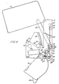
- a continuous towel cabinet comprises a back portion 10 to which a front cover 11 is hinged by pivots 12 and supported by side props 13. The lower ends of the props are attached for sliding movement in slots 51 ( Figure 3).
- the back portion 10 incorporates two side walls 14 from which a clean towel bin 15 is hung.
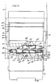
- the bin 15 When the cover 11 is open, the bin 15 is capable of forward and downward movement into a loading position ( Figures 3 and 4), but is normally held locked in its operative position ( Figures 1 and 2) by the closed cover.
- the side walls 14 extend an arrangement of rollers which allow clean towel 9 to be dispensed from a roll within the bin 15 into a loop 16 below the bin.
- the towel passes upwardly over a roughened metering roller 17, around a guide roll 18 and then downwardly into the loop 16.
- the towel 9, which is then described as soiled towel is withdrawn into the cabinet by take-up means comprising a pair of rollers 41, 42.
- the soiled towel is fed by the rollers 41, 42 into a compartment 19 formed by a pivotally mounted tray 20. At least initially the tray rests on the roll of clean towel in the bin 15.
- the tray 20 and a partition 40 also combine to keep the soiled towel clearly separate from the clean towel roll in the bin 15.
- the compartment 19 acts as a store for the soiled towel before it is rewound onto the rewind roller 21 mounted in generally upwardly extending grooves 22 in the side walls 14 and which is driven by another roughened metering roller 23 through the outermost turn of the towel which has been rewound.
- a respective gear wheel 24, 25 which wheels mesh with an intermediate gear wheel 26 ( Figure 2).
- the gear wheels 24, 25 have the same number of teeth so that the length of soiled towel rewound on the rewind roller 21 is the same as the length of towel dispensed at the front of the cabinet.
- the lower roller 41 also has a unidirectional clutch bearing 28 ( Figure 4) in one end, the clutch bearings in the rollers 41, 42 combining to resist rotation of the respective roller in the reverse directional movement of the towel, thereby at least resisting the user from pulling soiled towel from the back of the cabinet.
- Each roller 41, 42 in this embodiment has an inner sleeve 55 on which are assembled a set of five outer, longitudinally fluted rubber sleeve portions 43 for gripping the towel.
- the drive to the roller 41 is a belt drive 31 driven by an electric motor 32 via a gear box 33.
- the drive 31 may be a chain drive or gear train.
- the clutch bearing 28 in the roller 41 is a needle roller clutch bearing which allows the roller 18 to be rotated freely when driving the towel into the cabinet, but is engaged if a torque is applied in the reverse direction, i.e. if the user tries to pull the towel back.
- the clutch bearing in the upper roller 42 is also of a similar type, but in either case the clutch bearing may be of another type, e.g. having a ratchet or pawl arrangement.
- the drive motor 32 is an electric motor, operated from an independent low power DC energy source, for example one or more alkaline batteries 44, disposed within the cabinet.
- the control means for the electric motor 32 is an integrated circuit 35 which in this embodiment is made operative, in that it senses a voltage, when the clean towel bin 15 is in its raised operative position. This is achieved by a micro-switch 36 having a lever which is operated to make or break the switch 36 by movement of the bin 15 into and from its operative position respectively.
- one of the side walls 14 carries a steel strip 36 which is electrically connected to the circuit and which, during the closing movement of the cover, makes contact with one of the side props 13 and thereby earths out on the back portion 10 of the cabinet.
- the control means further include sensing means responsive to the tension in the towel.
- the sensing means is a micro- switch 37 ( Figure 2) having a lever 38 operated by a bar 52 to close the switch 37 and thereby switch off the motor 32, when the towel is tight, i.e. when the loop 16 is retracted against the underside of the clean towel bin 15.
- the sensing means is thus activated by the tension in the towel and, in this embodiment, the bar 52 makes contact with the towel across its complete width. This is an advantage because should the loop of towel become bunched at one side or the other, perhaps through misuse, the mechanism will remain operative to retract the loop.
- the ends of the bar 52 are mounted in slots 53 inclined downwardly away from the switch 37, the bar being pushed up the slots to switch off the motor 32 when the towel is tight ( Figure 2).
- the micro-switch 37 is also disposed mid-way along the bar 52. Thus should side bunching of the towel occur, the bar can pivot within the limits of the slots 53 without affecting its operation of the micro-switch. Dispensing fresh towel loosens the towel, and allows the bar 52 to fall down the slots 53 thereby removing its pressure on the lever 38.
- the micro-switch 37 opens and after a time delay, e.g. 7 seconds, controlled by the integrated circuit, the motor 32 is switched on to retract the loop 16.
- the integrated circuit also determines the maximum period of operation of the motor, which, in this embodiment, is 8 seconds. In normal operation, of course, the full period of operation is not employed because the loop retracts in less than 8 seconds and the motor 32 is switched off by the micro-switch 37. However, when the end of the towel is reached, the time period of operation of the motor is sufficient to withdraw into the cabinet the trailing end, the motor switching off at the end of the full period. If, during normal retraction of the loop 16 or during withdrawal of the trailing end of the towel, the towel should be held, the cycle is automatically stopped and restarted, including an initial time delay and the available full period of operation of the motor, when the towel is no longer held. If necessary the stop and restart process will be repeated until the loop has been retracted or the trailing end withdrawn.
Landscapes
- Health & Medical Sciences (AREA)
- Public Health (AREA)
- Unwinding Webs (AREA)
- Body Washing Hand Wipes And Brushes (AREA)
- Brushes (AREA)
- Winding Of Webs (AREA)
- Containers And Plastic Fillers For Packaging (AREA)
- Paper (AREA)
Claims (12)
Priority Applications (1)
| Application Number | Priority Date | Filing Date | Title |
|---|---|---|---|
| AT88303365T ATE64843T1 (de) | 1987-04-22 | 1988-04-14 | Ausgeber fuer eine handtuchbahn. |
Applications Claiming Priority (2)
| Application Number | Priority Date | Filing Date | Title |
|---|---|---|---|
| GB8709510 | 1987-04-22 | ||
| GB878709510A GB8709510D0 (en) | 1987-04-22 | 1987-04-22 | Continuous towel cabinets |
Publications (2)
| Publication Number | Publication Date |
|---|---|
| EP0288211A1 EP0288211A1 (fr) | 1988-10-26 |
| EP0288211B1 true EP0288211B1 (fr) | 1991-07-03 |
Family
ID=10616162
Family Applications (1)
| Application Number | Title | Priority Date | Filing Date |
|---|---|---|---|
| EP88303365A Expired - Lifetime EP0288211B1 (fr) | 1987-04-22 | 1988-04-14 | Distributeurs pour bande de serviette |
Country Status (6)
| Country | Link |
|---|---|
| US (1) | US4848854A (fr) |
| EP (1) | EP0288211B1 (fr) |
| AT (1) | ATE64843T1 (fr) |
| DE (1) | DE3863465D1 (fr) |
| ES (1) | ES2022987B3 (fr) |
| GB (2) | GB8709510D0 (fr) |
Families Citing this family (18)
| Publication number | Priority date | Publication date | Assignee | Title |
|---|---|---|---|---|
| DE3843851A1 (de) * | 1988-12-24 | 1990-06-28 | Schumm Erich Kg | Handtuchspender |
| GB2242673B (en) * | 1990-04-03 | 1993-12-08 | David Kennedy | Continuous towel cabinets |
| CH681350A5 (fr) * | 1990-05-15 | 1993-03-15 | Cws Ag | |
| DE4020707C2 (de) * | 1990-06-29 | 2003-04-30 | Schumm Erich Kg | Handtuch-Ausgeber |
| DE4310716A1 (de) * | 1993-04-01 | 1994-10-06 | Schumm Erich Gmbh | Handtuchspender für Rollenhandtücher |
| DE4422182A1 (de) * | 1994-06-28 | 1996-01-04 | Schumm Erich Gmbh | Handtuchspender für Rollen-Handtücher |
| US7044421B1 (en) | 1999-04-20 | 2006-05-16 | The Colman Group, Inc. | Electronically controlled roll towel dispenser with data communication system |
| US6736466B1 (en) | 2002-08-27 | 2004-05-18 | Steven R. Helland | Paper towel dispensing apparatus |
| NL1034374C2 (nl) * | 2007-09-12 | 2009-03-16 | Vendor Bv | Cassette voor een handdoekautomaat en handdoekautomaat voor toepassing van een dergelijke cassette. |
| NL1034377C2 (nl) * | 2007-09-12 | 2009-03-16 | Vendor Bv | Handdoekautomaat en cassette voor een handdoekautomaat. |
| US20100102101A1 (en) * | 2008-10-28 | 2010-04-29 | Perrin Manufacturing Company | Paper toweling dispenser apparatus |
| US8555761B2 (en) | 2008-10-28 | 2013-10-15 | Dispensing Dynamics International | Paper sheet material dispenser apparatus |
| US9248988B2 (en) | 2009-05-27 | 2016-02-02 | Dispensing Dynamics International | Multi-function dispenser for dispensing paper sheet material |
| US9345367B2 (en) | 2009-05-27 | 2016-05-24 | Dispensing Dynamics International | Multi-function paper toweling dispenser |
| US8382026B2 (en) * | 2009-05-27 | 2013-02-26 | Dispensing Dynamics International | Multi-function paper toweling dispenser |
| US8511599B2 (en) * | 2010-03-04 | 2013-08-20 | Richard LaLau | Paper towel dispensing systems |
| US9730559B2 (en) | 2014-04-10 | 2017-08-15 | Dispensing Dynamics International, Llc | Electro-mechanical paper sheet material dispenser with tail sensor |
| USD860674S1 (en) | 2018-02-06 | 2019-09-24 | San Jamar, Inc. | Towel dispenser |
Family Cites Families (19)
| Publication number | Priority date | Publication date | Assignee | Title |
|---|---|---|---|---|
| US1809873A (en) * | 1925-03-16 | 1931-06-16 | Steiner Sales Co | Towel cabinet |
| US2103403A (en) * | 1935-04-08 | 1937-12-28 | Steiner Sales Co | Towel dispensing apparatus |
| US3214226A (en) * | 1963-05-10 | 1965-10-26 | Steiner American Corp | Towel dispenser |
| US3323848A (en) * | 1965-05-03 | 1967-06-06 | Steiner American Corp | Towel dispensing apparatus |
| GB1137003A (en) * | 1965-12-31 | 1968-12-18 | Strattwell Developments Ltd | Improved apparatus for dispensing towelling |
| GB1192546A (en) * | 1966-07-06 | 1970-05-20 | Strattwell Developments Ltd | Improved Apparatus for Dispensing Towelling |
| GB1138447A (en) * | 1966-07-11 | 1969-01-01 | Strattwell Developments Ltd | Improved apparatus for dispensing towelling |
| CH455194A (de) * | 1967-09-08 | 1968-04-30 | W Schnyder Conrad | Handtuch-Automat |
| GB1288780A (fr) * | 1969-10-27 | 1972-09-13 | ||
| US3637275A (en) * | 1970-01-15 | 1972-01-25 | Steiner American Corp | Towel dispenser with covered clean towel receptacle |
| US3728001A (en) * | 1971-01-27 | 1973-04-17 | Steiner American Corp | Towel dispensing cabinet with scraper attachment |
| CH528256A (de) * | 1972-01-28 | 1972-09-30 | Cws Int Ag | Handtuchbahnausgeber |
| CH531340A (de) * | 1972-01-28 | 1972-12-15 | Cws Int Ag | Handtuchbahnausgeber |
| US3893738A (en) * | 1973-04-30 | 1975-07-08 | Steiner American Corp | Retractable towel cabinet |
| GB1596283A (en) * | 1977-09-02 | 1981-08-26 | Saltney Eng Co Ltd | Linen towel cabinets |
| GB2120205B (en) * | 1982-05-20 | 1985-07-31 | Kennedy David | Continuous towel cabinet |
| GB8300477D0 (en) * | 1983-01-08 | 1983-02-09 | Glynwed Screws & Fastenings Lt | Dispensing apparatus |
| DE3416718A1 (de) * | 1983-06-24 | 1985-01-03 | CWS AG, Baar | Verfahren und vorrichtung zum einziehen von handtuchschlaufen und handtuchenden an einem stoffhandtuchspender |
| DE3432694A1 (de) * | 1984-09-06 | 1986-03-13 | Erich Schumm Gmbh, 7157 Murrhardt | Handtuch-spender |
-
1987
- 1987-04-22 GB GB878709510A patent/GB8709510D0/en active Pending
-
1988
- 1988-04-11 US US07/180,116 patent/US4848854A/en not_active Expired - Fee Related
- 1988-04-14 ES ES88303365T patent/ES2022987B3/es not_active Expired - Lifetime
- 1988-04-14 GB GB8808800A patent/GB2203725B/en not_active Expired - Fee Related
- 1988-04-14 EP EP88303365A patent/EP0288211B1/fr not_active Expired - Lifetime
- 1988-04-14 DE DE8888303365T patent/DE3863465D1/de not_active Expired - Lifetime
- 1988-04-14 AT AT88303365T patent/ATE64843T1/de not_active IP Right Cessation
Also Published As
| Publication number | Publication date |
|---|---|
| US4848854A (en) | 1989-07-18 |
| ATE64843T1 (de) | 1991-07-15 |
| EP0288211A1 (fr) | 1988-10-26 |
| DE3863465D1 (de) | 1991-08-08 |
| ES2022987B3 (es) | 1991-12-16 |
| GB2203725B (en) | 1991-05-01 |
| GB8808800D0 (en) | 1988-05-18 |
| GB8709510D0 (en) | 1987-05-28 |
| GB2203725A (en) | 1988-10-26 |
Similar Documents
| Publication | Publication Date | Title |
|---|---|---|
| US4848854A (en) | Continuous towel cabinets | |
| US5375920A (en) | Handtowel dispenser | |
| US4165138A (en) | Dispenser cabinet for sheet material and transfer mechanism | |
| US8555761B2 (en) | Paper sheet material dispenser apparatus | |
| US6237871B1 (en) | Paper towel transfer apparatus | |
| US7270292B2 (en) | Web transfer mechanism for flexible sheet dispenser | |
| US4307638A (en) | Method of dispersing flexible sheet material | |
| US4131044A (en) | Cut-off mechanism for paper towel dispenser | |
| US4487375A (en) | Roll transfer mechanism for web material dispenser | |
| US20100102101A1 (en) | Paper toweling dispenser apparatus | |
| WO2007068271A1 (fr) | Dispositif de chargement de distributeur, et procédé de chargement de distributeur | |
| US4634192A (en) | Roller towel apparatus | |
| US5244263A (en) | Continuous towel cabinets | |
| US4573750A (en) | Dispensing apparatus | |
| FI58258C (fi) | Handduksutmatningsanordning | |
| US20120273605A1 (en) | Cover actuated roll towel dispense | |
| EP0202078B1 (fr) | Distributeur de serviettes | |
| JPS5850729B2 (ja) | テフキタオルブンヨソウチ | |
| US20080302901A1 (en) | Roll towel dispenser | |
| EP2846669A1 (fr) | Appareil distributeur de matériau de feuille de papier | |
| US20020145364A1 (en) | Towel loop formation in a hand towel dispenser | |
| EP0095318B1 (fr) | Boîtiers pour essuie-main continu | |
| JP4328048B2 (ja) | ハンドタオルディスペンサ | |
| EP0839014B1 (fr) | Derouleur de bande-serviette pour s'essuyer les mains | |
| JPH047212B2 (fr) |
Legal Events
| Date | Code | Title | Description |
|---|---|---|---|
| PUAI | Public reference made under article 153(3) epc to a published international application that has entered the european phase |
Free format text: ORIGINAL CODE: 0009012 |
|
| AK | Designated contracting states |
Kind code of ref document: A1 Designated state(s): AT BE CH DE ES FR IT LI NL SE |
|
| 17P | Request for examination filed |
Effective date: 19890401 |
|
| 17Q | First examination report despatched |
Effective date: 19890928 |
|
| GRAA | (expected) grant |
Free format text: ORIGINAL CODE: 0009210 |
|
| AK | Designated contracting states |
Kind code of ref document: B1 Designated state(s): AT BE CH DE ES FR IT LI NL SE |
|
| REF | Corresponds to: |
Ref document number: 64843 Country of ref document: AT Date of ref document: 19910715 Kind code of ref document: T |
|
| REF | Corresponds to: |
Ref document number: 3863465 Country of ref document: DE Date of ref document: 19910808 |
|
| ET | Fr: translation filed | ||
| ITF | It: translation for a ep patent filed | ||
| PLBE | No opposition filed within time limit |
Free format text: ORIGINAL CODE: 0009261 |
|
| STAA | Information on the status of an ep patent application or granted ep patent |
Free format text: STATUS: NO OPPOSITION FILED WITHIN TIME LIMIT |
|
| 26N | No opposition filed | ||
| EAL | Se: european patent in force in sweden |
Ref document number: 88303365.6 |
|
| PGFP | Annual fee paid to national office [announced via postgrant information from national office to epo] |
Ref country code: DE Payment date: 20020624 Year of fee payment: 15 |
|
| PGFP | Annual fee paid to national office [announced via postgrant information from national office to epo] |
Ref country code: FR Payment date: 20030527 Year of fee payment: 16 Ref country code: AT Payment date: 20030527 Year of fee payment: 16 |
|
| PGFP | Annual fee paid to national office [announced via postgrant information from national office to epo] |
Ref country code: NL Payment date: 20030528 Year of fee payment: 16 |
|
| PGFP | Annual fee paid to national office [announced via postgrant information from national office to epo] |
Ref country code: ES Payment date: 20030529 Year of fee payment: 16 |
|
| PGFP | Annual fee paid to national office [announced via postgrant information from national office to epo] |
Ref country code: SE Payment date: 20030530 Year of fee payment: 16 |
|
| PGFP | Annual fee paid to national office [announced via postgrant information from national office to epo] |
Ref country code: CH Payment date: 20030606 Year of fee payment: 16 |
|
| PGFP | Annual fee paid to national office [announced via postgrant information from national office to epo] |
Ref country code: BE Payment date: 20030611 Year of fee payment: 16 |
|
| PG25 | Lapsed in a contracting state [announced via postgrant information from national office to epo] |
Ref country code: DE Free format text: LAPSE BECAUSE OF NON-PAYMENT OF DUE FEES Effective date: 20031101 |
|
| PG25 | Lapsed in a contracting state [announced via postgrant information from national office to epo] |
Ref country code: AT Free format text: LAPSE BECAUSE OF NON-PAYMENT OF DUE FEES Effective date: 20040414 |
|
| PG25 | Lapsed in a contracting state [announced via postgrant information from national office to epo] |
Ref country code: SE Free format text: LAPSE BECAUSE OF NON-PAYMENT OF DUE FEES Effective date: 20040415 Ref country code: ES Free format text: LAPSE BECAUSE OF NON-PAYMENT OF DUE FEES Effective date: 20040415 |
|
| PG25 | Lapsed in a contracting state [announced via postgrant information from national office to epo] |
Ref country code: LI Free format text: LAPSE BECAUSE OF NON-PAYMENT OF DUE FEES Effective date: 20040430 Ref country code: CH Free format text: LAPSE BECAUSE OF NON-PAYMENT OF DUE FEES Effective date: 20040430 Ref country code: BE Free format text: LAPSE BECAUSE OF NON-PAYMENT OF DUE FEES Effective date: 20040430 |
|
| BERE | Be: lapsed |
Owner name: *DAVID KENNEDY (ENGINEERS) HOLDINGS LTD Effective date: 20040430 |
|
| PG25 | Lapsed in a contracting state [announced via postgrant information from national office to epo] |
Ref country code: NL Free format text: LAPSE BECAUSE OF NON-PAYMENT OF DUE FEES Effective date: 20041101 |
|
| EUG | Se: european patent has lapsed | ||
| REG | Reference to a national code |
Ref country code: CH Ref legal event code: PL |
|
| PG25 | Lapsed in a contracting state [announced via postgrant information from national office to epo] |
Ref country code: FR Free format text: LAPSE BECAUSE OF NON-PAYMENT OF DUE FEES Effective date: 20041231 |
|
| NLV4 | Nl: lapsed or anulled due to non-payment of the annual fee |
Effective date: 20041101 |
|
| REG | Reference to a national code |
Ref country code: FR Ref legal event code: ST |
|
| PG25 | Lapsed in a contracting state [announced via postgrant information from national office to epo] |
Ref country code: IT Free format text: LAPSE BECAUSE OF NON-PAYMENT OF DUE FEES;WARNING: LAPSES OF ITALIAN PATENTS WITH EFFECTIVE DATE BEFORE 2007 MAY HAVE OCCURRED AT ANY TIME BEFORE 2007. THE CORRECT EFFECTIVE DATE MAY BE DIFFERENT FROM THE ONE RECORDED. Effective date: 20050414 |
|
| REG | Reference to a national code |
Ref country code: ES Ref legal event code: FD2A Effective date: 20040415 |