EP0288602A2 - Laser - Google Patents
Laser Download PDFInfo
- Publication number
- EP0288602A2 EP0288602A2 EP87116618A EP87116618A EP0288602A2 EP 0288602 A2 EP0288602 A2 EP 0288602A2 EP 87116618 A EP87116618 A EP 87116618A EP 87116618 A EP87116618 A EP 87116618A EP 0288602 A2 EP0288602 A2 EP 0288602A2
- Authority
- EP
- European Patent Office
- Prior art keywords
- laser
- discharge
- resonator
- circuit
- mirror
- Prior art date
- Legal status (The legal status is an assumption and is not a legal conclusion. Google has not performed a legal analysis and makes no representation as to the accuracy of the status listed.)
- Withdrawn
Links
- 230000006872 improvement Effects 0.000 title description 3
- 238000000605 extraction Methods 0.000 claims abstract description 3
- 230000003287 optical effect Effects 0.000 claims description 45
- 238000002310 reflectometry Methods 0.000 claims description 37
- 230000000694 effects Effects 0.000 claims description 17
- 101150090341 dst1 gene Proteins 0.000 claims description 3
- 230000000977 initiatory effect Effects 0.000 claims description 3
- 238000009966 trimming Methods 0.000 claims description 3
- 238000010521 absorption reaction Methods 0.000 description 25
- BJQHLKABXJIVAM-UHFFFAOYSA-N bis(2-ethylhexyl) phthalate Chemical compound CCCCC(CC)COC(=O)C1=CC=CC=C1C(=O)OCC(CC)CCCC BJQHLKABXJIVAM-UHFFFAOYSA-N 0.000 description 25
- 238000005259 measurement Methods 0.000 description 19
- 238000010586 diagram Methods 0.000 description 15
- 238000001228 spectrum Methods 0.000 description 14
- 230000003595 spectral effect Effects 0.000 description 12
- 230000007704 transition Effects 0.000 description 10
- 238000002835 absorbance Methods 0.000 description 9
- VGGSQFUCUMXWEO-UHFFFAOYSA-N Ethene Chemical compound C=C VGGSQFUCUMXWEO-UHFFFAOYSA-N 0.000 description 8
- 239000005977 Ethylene Substances 0.000 description 8
- 230000008859 change Effects 0.000 description 8
- 238000003491 array Methods 0.000 description 7
- 230000008901 benefit Effects 0.000 description 7
- 239000003990 capacitor Substances 0.000 description 7
- 238000000034 method Methods 0.000 description 7
- 230000004044 response Effects 0.000 description 7
- 230000005540 biological transmission Effects 0.000 description 6
- 238000001816 cooling Methods 0.000 description 6
- 230000006870 function Effects 0.000 description 6
- 101100476979 Rhodobacter capsulatus sdsA gene Proteins 0.000 description 5
- 230000009471 action Effects 0.000 description 5
- 238000006243 chemical reaction Methods 0.000 description 5
- 239000002131 composite material Substances 0.000 description 5
- 230000005855 radiation Effects 0.000 description 5
- 229910001220 stainless steel Inorganic materials 0.000 description 5
- 239000010935 stainless steel Substances 0.000 description 5
- 150000001875 compounds Chemical class 0.000 description 4
- 238000006073 displacement reaction Methods 0.000 description 4
- 230000001976 improved effect Effects 0.000 description 4
- 238000012216 screening Methods 0.000 description 4
- 238000003860 storage Methods 0.000 description 4
- 229910001374 Invar Inorganic materials 0.000 description 3
- 229910052782 aluminium Inorganic materials 0.000 description 3
- 238000012937 correction Methods 0.000 description 3
- 238000007667 floating Methods 0.000 description 3
- 229910052732 germanium Inorganic materials 0.000 description 3
- GNPVGFCGXDBREM-UHFFFAOYSA-N germanium atom Chemical compound [Ge] GNPVGFCGXDBREM-UHFFFAOYSA-N 0.000 description 3
- 238000002955 isolation Methods 0.000 description 3
- 239000000203 mixture Substances 0.000 description 3
- 230000002829 reductive effect Effects 0.000 description 3
- 150000003839 salts Chemical class 0.000 description 3
- 238000000926 separation method Methods 0.000 description 3
- 241000894007 species Species 0.000 description 3
- 230000006641 stabilisation Effects 0.000 description 3
- 238000011105 stabilization Methods 0.000 description 3
- 238000012360 testing method Methods 0.000 description 3
- 230000001960 triggered effect Effects 0.000 description 3
- PFNQVRZLDWYSCW-UHFFFAOYSA-N (fluoren-9-ylideneamino) n-naphthalen-1-ylcarbamate Chemical compound C12=CC=CC=C2C2=CC=CC=C2C1=NOC(=O)NC1=CC=CC2=CC=CC=C12 PFNQVRZLDWYSCW-UHFFFAOYSA-N 0.000 description 2
- 101100332288 Dictyostelium discoideum dst3 gene Proteins 0.000 description 2
- 229910000661 Mercury cadmium telluride Inorganic materials 0.000 description 2
- 101100309605 Saccharomyces cerevisiae (strain ATCC 204508 / S288c) SCD5 gene Proteins 0.000 description 2
- 230000004913 activation Effects 0.000 description 2
- 239000004411 aluminium Substances 0.000 description 2
- XAGFODPZIPBFFR-UHFFFAOYSA-N aluminium Chemical compound [Al] XAGFODPZIPBFFR-UHFFFAOYSA-N 0.000 description 2
- 230000003466 anti-cipated effect Effects 0.000 description 2
- 238000013459 approach Methods 0.000 description 2
- 230000035559 beat frequency Effects 0.000 description 2
- 238000004422 calculation algorithm Methods 0.000 description 2
- 230000015556 catabolic process Effects 0.000 description 2
- 238000012512 characterization method Methods 0.000 description 2
- 239000011248 coating agent Substances 0.000 description 2
- 238000000576 coating method Methods 0.000 description 2
- 230000000295 complement effect Effects 0.000 description 2
- 239000004020 conductor Substances 0.000 description 2
- 239000013078 crystal Substances 0.000 description 2
- 238000013500 data storage Methods 0.000 description 2
- 230000001419 dependent effect Effects 0.000 description 2
- 238000013461 design Methods 0.000 description 2
- 238000011161 development Methods 0.000 description 2
- 230000018109 developmental process Effects 0.000 description 2
- 238000009826 distribution Methods 0.000 description 2
- 230000009977 dual effect Effects 0.000 description 2
- 239000000428 dust Substances 0.000 description 2
- 230000005684 electric field Effects 0.000 description 2
- 230000005670 electromagnetic radiation Effects 0.000 description 2
- 238000005516 engineering process Methods 0.000 description 2
- 238000002474 experimental method Methods 0.000 description 2
- 230000004907 flux Effects 0.000 description 2
- 238000009499 grossing Methods 0.000 description 2
- 238000005286 illumination Methods 0.000 description 2
- 238000007689 inspection Methods 0.000 description 2
- 230000000670 limiting effect Effects 0.000 description 2
- 238000004519 manufacturing process Methods 0.000 description 2
- UPBAOYRENQEPJO-UHFFFAOYSA-N n-[5-[[5-[(3-amino-3-iminopropyl)carbamoyl]-1-methylpyrrol-3-yl]carbamoyl]-1-methylpyrrol-3-yl]-4-formamido-1-methylpyrrole-2-carboxamide Chemical compound CN1C=C(NC=O)C=C1C(=O)NC1=CN(C)C(C(=O)NC2=CN(C)C(C(=O)NCCC(N)=N)=C2)=C1 UPBAOYRENQEPJO-UHFFFAOYSA-N 0.000 description 2
- 230000000737 periodic effect Effects 0.000 description 2
- 230000009467 reduction Effects 0.000 description 2
- 238000005070 sampling Methods 0.000 description 2
- 230000003068 static effect Effects 0.000 description 2
- 230000001052 transient effect Effects 0.000 description 2
- WFKWXMTUELFFGS-UHFFFAOYSA-N tungsten Chemical compound [W] WFKWXMTUELFFGS-UHFFFAOYSA-N 0.000 description 2
- 229910052721 tungsten Inorganic materials 0.000 description 2
- 239000010937 tungsten Substances 0.000 description 2
- 238000012935 Averaging Methods 0.000 description 1
- 229910001369 Brass Inorganic materials 0.000 description 1
- OKTJSMMVPCPJKN-UHFFFAOYSA-N Carbon Chemical compound [C] OKTJSMMVPCPJKN-UHFFFAOYSA-N 0.000 description 1
- 101100067255 Fusarium sp. (strain FN080326) fsa2 gene Proteins 0.000 description 1
- 244000050403 Iris x germanica Species 0.000 description 1
- 240000007643 Phytolacca americana Species 0.000 description 1
- 238000001069 Raman spectroscopy Methods 0.000 description 1
- 241000283984 Rodentia Species 0.000 description 1
- 101100279972 Saccharomyces cerevisiae (strain ATCC 204508 / S288c) ERG20 gene Proteins 0.000 description 1
- 239000004809 Teflon Substances 0.000 description 1
- 229920006362 Teflon® Polymers 0.000 description 1
- AZDRQVAHHNSJOQ-UHFFFAOYSA-N alumane Chemical compound [AlH3] AZDRQVAHHNSJOQ-UHFFFAOYSA-N 0.000 description 1
- 238000004458 analytical method Methods 0.000 description 1
- 238000010009 beating Methods 0.000 description 1
- 230000015572 biosynthetic process Effects 0.000 description 1
- 239000010951 brass Substances 0.000 description 1
- 238000004364 calculation method Methods 0.000 description 1
- 229910052799 carbon Inorganic materials 0.000 description 1
- 239000000969 carrier Substances 0.000 description 1
- 239000000919 ceramic Substances 0.000 description 1
- 238000004891 communication Methods 0.000 description 1
- 239000000470 constituent Substances 0.000 description 1
- 239000002826 coolant Substances 0.000 description 1
- 239000000110 cooling liquid Substances 0.000 description 1
- 230000007812 deficiency Effects 0.000 description 1
- 230000003111 delayed effect Effects 0.000 description 1
- 230000006866 deterioration Effects 0.000 description 1
- 230000002708 enhancing effect Effects 0.000 description 1
- 230000003628 erosive effect Effects 0.000 description 1
- 239000000835 fiber Substances 0.000 description 1
- 238000001914 filtration Methods 0.000 description 1
- 238000010438 heat treatment Methods 0.000 description 1
- 230000001939 inductive effect Effects 0.000 description 1
- 238000003780 insertion Methods 0.000 description 1
- 230000037431 insertion Effects 0.000 description 1
- 238000009434 installation Methods 0.000 description 1
- 230000003993 interaction Effects 0.000 description 1
- 230000001788 irregular Effects 0.000 description 1
- 230000007774 longterm Effects 0.000 description 1
- 238000012423 maintenance Methods 0.000 description 1
- 239000000463 material Substances 0.000 description 1
- 239000011159 matrix material Substances 0.000 description 1
- 230000007246 mechanism Effects 0.000 description 1
- 229910052751 metal Inorganic materials 0.000 description 1
- 239000002184 metal Substances 0.000 description 1
- 238000012544 monitoring process Methods 0.000 description 1
- 238000005457 optimization Methods 0.000 description 1
- 230000036961 partial effect Effects 0.000 description 1
- 229920001343 polytetrafluoroethylene Polymers 0.000 description 1
- 239000004810 polytetrafluoroethylene Substances 0.000 description 1
- 238000002360 preparation method Methods 0.000 description 1
- 230000008569 process Effects 0.000 description 1
- 230000001902 propagating effect Effects 0.000 description 1
- 238000005295 random walk Methods 0.000 description 1
- 230000002787 reinforcement Effects 0.000 description 1
- 230000000284 resting effect Effects 0.000 description 1
- 239000000758 substrate Substances 0.000 description 1
- 230000008093 supporting effect Effects 0.000 description 1
- 238000012546 transfer Methods 0.000 description 1
- 238000002834 transmittance Methods 0.000 description 1
- VLPFTAMPNXLGLX-UHFFFAOYSA-N trioctanoin Chemical compound CCCCCCCC(=O)OCC(OC(=O)CCCCCCC)COC(=O)CCCCCCC VLPFTAMPNXLGLX-UHFFFAOYSA-N 0.000 description 1
- XLYOFNOQVPJJNP-UHFFFAOYSA-N water Substances O XLYOFNOQVPJJNP-UHFFFAOYSA-N 0.000 description 1
- 238000005303 weighing Methods 0.000 description 1
- 238000004804 winding Methods 0.000 description 1
Images












Classifications
-
- H—ELECTRICITY
- H01—ELECTRIC ELEMENTS
- H01S—DEVICES USING THE PROCESS OF LIGHT AMPLIFICATION BY STIMULATED EMISSION OF RADIATION [LASER] TO AMPLIFY OR GENERATE LIGHT; DEVICES USING STIMULATED EMISSION OF ELECTROMAGNETIC RADIATION IN WAVE RANGES OTHER THAN OPTICAL
- H01S3/00—Lasers, i.e. devices using stimulated emission of electromagnetic radiation in the infrared, visible or ultraviolet wave range
- H01S3/10—Controlling the intensity, frequency, phase, polarisation or direction of the emitted radiation, e.g. switching, gating, modulating or demodulating
- H01S3/105—Controlling the intensity, frequency, phase, polarisation or direction of the emitted radiation, e.g. switching, gating, modulating or demodulating by controlling the mutual position or the reflecting properties of the reflectors of the cavity, e.g. by controlling the cavity length
- H01S3/1055—Controlling the intensity, frequency, phase, polarisation or direction of the emitted radiation, e.g. switching, gating, modulating or demodulating by controlling the mutual position or the reflecting properties of the reflectors of the cavity, e.g. by controlling the cavity length one of the reflectors being constituted by a diffraction grating
-
- G—PHYSICS
- G01—MEASURING; TESTING
- G01N—INVESTIGATING OR ANALYSING MATERIALS BY DETERMINING THEIR CHEMICAL OR PHYSICAL PROPERTIES
- G01N21/00—Investigating or analysing materials by the use of optical means, i.e. using sub-millimetre waves, infrared, visible or ultraviolet light
- G01N21/17—Systems in which incident light is modified in accordance with the properties of the material investigated
- G01N21/25—Colour; Spectral properties, i.e. comparison of effect of material on the light at two or more different wavelengths or wavelength bands
- G01N21/31—Investigating relative effect of material at wavelengths characteristic of specific elements or molecules, e.g. atomic absorption spectrometry
- G01N21/39—Investigating relative effect of material at wavelengths characteristic of specific elements or molecules, e.g. atomic absorption spectrometry using tunable lasers
-
- H—ELECTRICITY
- H01—ELECTRIC ELEMENTS
- H01S—DEVICES USING THE PROCESS OF LIGHT AMPLIFICATION BY STIMULATED EMISSION OF RADIATION [LASER] TO AMPLIFY OR GENERATE LIGHT; DEVICES USING STIMULATED EMISSION OF ELECTROMAGNETIC RADIATION IN WAVE RANGES OTHER THAN OPTICAL
- H01S3/00—Lasers, i.e. devices using stimulated emission of electromagnetic radiation in the infrared, visible or ultraviolet wave range
- H01S3/02—Constructional details
- H01S3/03—Constructional details of gas laser discharge tubes
- H01S3/036—Means for obtaining or maintaining the desired gas pressure within the tube, e.g. by gettering, replenishing; Means for circulating the gas, e.g. for equalising the pressure within the tube
-
- H—ELECTRICITY
- H01—ELECTRIC ELEMENTS
- H01S—DEVICES USING THE PROCESS OF LIGHT AMPLIFICATION BY STIMULATED EMISSION OF RADIATION [LASER] TO AMPLIFY OR GENERATE LIGHT; DEVICES USING STIMULATED EMISSION OF ELECTROMAGNETIC RADIATION IN WAVE RANGES OTHER THAN OPTICAL
- H01S3/00—Lasers, i.e. devices using stimulated emission of electromagnetic radiation in the infrared, visible or ultraviolet wave range
- H01S3/02—Constructional details
- H01S3/03—Constructional details of gas laser discharge tubes
- H01S3/038—Electrodes, e.g. special shape, configuration or composition
-
- H—ELECTRICITY
- H01—ELECTRIC ELEMENTS
- H01S—DEVICES USING THE PROCESS OF LIGHT AMPLIFICATION BY STIMULATED EMISSION OF RADIATION [LASER] TO AMPLIFY OR GENERATE LIGHT; DEVICES USING STIMULATED EMISSION OF ELECTROMAGNETIC RADIATION IN WAVE RANGES OTHER THAN OPTICAL
- H01S3/00—Lasers, i.e. devices using stimulated emission of electromagnetic radiation in the infrared, visible or ultraviolet wave range
- H01S3/05—Construction or shape of optical resonators; Accommodation of active medium therein; Shape of active medium
- H01S3/08—Construction or shape of optical resonators or components thereof
- H01S3/086—One or more reflectors having variable properties or positions for initial adjustment of the resonator
-
- H—ELECTRICITY
- H01—ELECTRIC ELEMENTS
- H01S—DEVICES USING THE PROCESS OF LIGHT AMPLIFICATION BY STIMULATED EMISSION OF RADIATION [LASER] TO AMPLIFY OR GENERATE LIGHT; DEVICES USING STIMULATED EMISSION OF ELECTROMAGNETIC RADIATION IN WAVE RANGES OTHER THAN OPTICAL
- H01S3/00—Lasers, i.e. devices using stimulated emission of electromagnetic radiation in the infrared, visible or ultraviolet wave range
- H01S3/09—Processes or apparatus for excitation, e.g. pumping
- H01S3/097—Processes or apparatus for excitation, e.g. pumping by gas discharge of a gas laser
- H01S3/0971—Processes or apparatus for excitation, e.g. pumping by gas discharge of a gas laser transversely excited
- H01S3/09713—Processes or apparatus for excitation, e.g. pumping by gas discharge of a gas laser transversely excited with auxiliary ionisation, e.g. double discharge excitation
-
- H—ELECTRICITY
- H01—ELECTRIC ELEMENTS
- H01S—DEVICES USING THE PROCESS OF LIGHT AMPLIFICATION BY STIMULATED EMISSION OF RADIATION [LASER] TO AMPLIFY OR GENERATE LIGHT; DEVICES USING STIMULATED EMISSION OF ELECTROMAGNETIC RADIATION IN WAVE RANGES OTHER THAN OPTICAL
- H01S3/00—Lasers, i.e. devices using stimulated emission of electromagnetic radiation in the infrared, visible or ultraviolet wave range
- H01S3/10—Controlling the intensity, frequency, phase, polarisation or direction of the emitted radiation, e.g. switching, gating, modulating or demodulating
- H01S3/13—Stabilisation of laser output parameters, e.g. frequency or amplitude
- H01S3/139—Stabilisation of laser output parameters, e.g. frequency or amplitude by controlling the mutual position or the reflecting properties of the reflectors of the cavity, e.g. by controlling the cavity length
Definitions
- the present invention relates to a laser.
- a laser comprising an optical resonator, characterised in that, resonator elements are controlled by a computer (CpU) to facilitate an energy extraction substantially concentrated in a single transverse mode.
- the resonator elements are orientated to provide maximum feedback to the computer from the output of the laser to extract the energy from the laser along a single optical axis thereof; the feedback signal from the laser being that whose spatially distributed energy is of a single gaussion form.
- the resonator elements are adjustable in such manner that the resonator can be substantially tuned over the emission bandwidth.
- the resonator may comprise two, three or four optical elements. In the case in which the resonator comprises more than two elements, preferably, the reflectivity of the resonator is optimised to assist frequency narrowing or selectivity imposed on the emission bandwidth of the laser medium.
- the said optical elements be mounted independently of the discharge chamber of the laser.
- the optical elements may be supported on a rail-mounted carriage, the carriage being slidable along the rail.
- the carriage and the rail may comprise a complementary dove-tail formation to prevent movement of the carriage other than said sliding movement therealong.
- Said means for effecting adjustment of the optical elements may comprise stepping motors; and the stepping motors may be supported on said carriage.
- the present invention is considered to be especially useful with a high-pressure gas laser.
- high pressure is intended to mean at least 5 atmospheres, more preferably at least 8 atmospheres and still more preferably some 10 atmospheres.
- the gas employed will usually be a multi-atmosphere gas e.g. a mixture o C02, N2 and He.
- the laser is continuously tunable.
- the laser of the present invention may comprise a discharge chamber constituted as a multiple electromagnetic screen in the form of a plurality of vessels located one within the other. They may be arranged coaxially; and it is presently preferred to employ two vessels sealed together at their axial ends and clamped thereat between end flanges held against the axial ends by tie rods passing between the two end flanges. The outermost vessel is directly earthed.
- the vessels may have axially and radially aligned access slots in which respective ports can be constructed to provide for circulation and cooling of laser gas and for admission of high-tension leads; or otherwise, serve as inspection or diagnostic ports.
- the high-pressure laser preferably employs pre-ionising electrode arrays; and, in one embodiment, four sliding spark arrays are employed one on each side of each main electrode.
- the main electrodes and the pre-ionising electrode arrays may employ a discharge circuit operating to release stored electrical energy on activation of a circuit make/break device inductively controlled by a trigger circuit providing the earth return for the discharge circuit.
- a discharge circuit operating to release stored electrical energy on activation of a circuit make/break device inductively controlled by a trigger circuit providing the earth return for the discharge circuit.
- the trigger or discharge circuit may comprise a current limiting resistor so that the circuit is effectively floating during discharge, or a switch to isolate the circuit from supply during discharge.
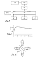
- the laser Ls in this instance a high-pressure, multi-atmosphere laser, with its optical cavity or resonator consisting of three elements OL1, OL2 and OL3, is diagrammatically illustrated.
- the three elements make up a "third-mirror" cavity and consist of a grating (OL1) a suppressor mirror (OL2) and an output coupler (OL3).
- the grating is mounted to be rotatable about three mutually perpendicular axes
- the suppressor mirror is mounted to be translatable towards and away from the grating, by respective stepping motors under the control of a computer Cpu.
- the computer also controls and monitors operation of the laser.
- the computer was an apple 11 plus device.
- a multiplexed I /0 MPE extension 25 of the Apple bus permits extra address lines for the control instructions.
- Circuitry mounted on individual "Eurocards" controls the trigger of the laser and measure the laser energies before and after the absorption cell.
- a diagram of this control system is shown in Fig. 2. The same computer is used through a separate interface to control the laser frequency and mode structure. The three main sections are discussed below.
- the high voltage trigger of the laser is activated with an optic unit, generally indicated at 11 and comprising a 'Radio Spares' opto-trans/receiver package and fibre cable.
- the computer Cpu initializes a programmable timer 13 which controls the timing of the pulse generator of the optic unit.
- the Software controlled timer allows arc-free operation between 0.1 and 10 Hz.
- the current software provides repetition frequencies up to 100 Hz.
- the optic unit fires the laser via a Hartley trigger HTT and the high-voltage supplies HVS
- the output of the laser was measured with thermal detectors 15,17, ( piezo-electric crystals with pyro- electro properties) with a rise time of 2 msec. and giving a maximum output voltage of 12.3 V/Joule linear with the incident photon flux.
- the beam passes through an absorption cell AC before passing to detector 17.
- the linearity of the detectors was within 2% and was checked with a calibrated Gentec pyro-electric calorimeter which had a 1% linearity.
- the trigger signal from a trigger unit 21 used to initialize the opto- isolated laser fire control simultaneously activates the pre-trigger of the 10-bit A/D converter 19 to sample the delayed maximum output voltage of the detectors.
- the time delay between laser fire and first AID conversion channel is also under software control and may be varied between 0.1 to 10 msec.
- the gain of the amplifier 23 following the A/D conversion is software selected. Four such AID conversion channels were provided, sampling being sequential over a period of 100 microsec. Considering the slow voltage variation at peak detector output level ( see Fig. 3,) neither of the 2% voltage variation over the sample period nor the 100 nsec. jitter between the P.I. trigger and the laser output are significant.
- the accuracy of an energy measurement is determined by the accuracy of the pre-amplifier gain, which was calibrated with a reference voltage; an accuracy of 2% at all gain settings (0 -42 dB) could be obtained.
- Identical translational stepper motors (see Fig. 9 especially) control the positions of the elements in the linear three mirror cavity.
- a stepper motor SM is exemplified in Fig.4.
- a pair of energized stator windings are represented by the magnetic poles A - D with polarities as shown.
- Table 2 shows a series of stator polarities that would make the rotor rotate with half step increments ("ON" would indicate polarity on "N", while "OFF” indicates that the polarity is removed). Such a sequence would be put out by the logic interface board controlling a stepper micrometer.
- LDT linear digital transducter
- the half step mode will produce a 1 micron positional increment of the output spindle for each half step of the stepper motor.
- the stepper motor uses currents of 0.5A or 1 A (depending on whether one or both stators are energized).
- the step rate can be varied under computer control between 20 and 1000 half steps per second without ramping.
- Two limit switches (not shown) are activated in order to shut the motor down before it runs into its end of travel stops.
- a knob at the rear of the steppermike can be used to make manual adjustments when the motor mike is not energized.
- Backlash introduces an additional displacement of approximately 0.5 micrometer after each full or half step sequence.
- the reproducibility for a 200 steps uni-and bi-directional movement is less than 2 micrometre.
- a Digiplan LD2 stepper motor driver (not shown) controls the LDT's.
- the input ports of the Digiplan circuit board are originally activated through an open collector NPN transistor by the "annunciator" outputs (an IEEE socket) of an Apple II plus computer. These four outputs used look after both direction and clock pulses for two LET's. At each end of micrometer travel the clock pulses are automatically inhibited by micro switches until the direction is reversed. There is no absolute position or direction indication on the LDT's available as a signal output to the computer, so that a relative position and direction control are used.
- C02 laser action is based on energy transfer between vibration/rotational C02 levels of the excited molecules. These bands produce radiation on four emission regions in the 9 u.m and 10am regions and are usually referred to as the 9p, 9R, and 10R branches. The individual laser transitions are being specified by an index J.
- P represents the partial pressure of each corresponding constituent in atmosphere and ⁇ v is obtained in GHz.
- the collision broadening coefficient is also temperature dependent.
- P the standard pressure of 1 atm.
- T the gas temperature in Kelvin.
- P the total pressure
- T the gas temperature in Kelvin.
- the accompanying pressure shift which is of relevance to tropospheric absorption splectroscopy is discussed.
- Figures which have been reported for pure C02 are -19.7 Hz/Torr. More recently reported values are considerably less -5.6 Hz/Torr; these values implying that the pressure shift becomes larger and non-linear at high pressures.
- the tuning ranges of the low pressure C02 lasers used are very limiting and are not representative of shifts at multi-atmospheric pressures.
- the cavity of the MAL multi-atmosphere laser
- the cavity of the MAL consists of the inversion medium and the free propagation distances between the brewster windows and the resonator mirrors.
- the main factors which determine the frequency stabilization of the laser are the cavity components (reflectivity) and the mechanical support structure (reflector position).
- the cavity components were mounted on a rigid rail.
- invar ( ⁇ 1 * 10 -6 K- 1 ) or low-expansion ceramic ( ⁇ 1 * 10 -8 K- 1 ) based cavity support structures used to minimize the change in cavity length in a passive way and frequency drift coefficients below 11 MHz/K were possible in CW - C02 lasers. In the present case this would have led to an impractical resonator structure, considering the dimensions of the MAL.
- the hollow aluminum bar shaped Oriel rail (27) was used to mount inter alia elements OL1, OL2 .
- the bar is rigid but has a high thermal expansion coefficient. -6 ( ⁇ 24 * 10 K -1 ).
- the slow temperature drift can be compensated for with commercial PLZT based transducers, but this requires a mode hop function at the end of the travel range. This would complicate the locking of the multi- mirror cavity, because ultimately the third mirror and gating have to move in step with one another for SLM operation.
- a dovetail guide rail R supports a laser Ls, two fixed saddles FSals and FSa2 and two slidably displaceable saddles SDS1 and SDS2.
- the displaceable saddle FDS1 supports a rigid transverse bar FTB1 which present a pivot pin PV1 upon which a bar B1 is pivotally supported adjacent one end.
- the actuating laser of a stepping motor LDT 25 engages the free end of bar B1, an adjusting screw AS1 supported by fixed saddle FSa1 engages the - bar B1 between the pivoted end and the free end thereof, closer to the pivoted end, and a tension spring TS1 extending between the fixed saddle FSa1 and the displaceable saddle SDS1 maintain the bar B1 in pressure engagement with the adjusting screw AS1.
- the bar B1 is caused to displace angularly about the contact with adjusting screw AS1 whereby the displace the displaceable saddle SDS1 in one direction or the other along the guiderail R.
- the displaceable saddle SDS2 supports a rigid transverse bar FTB1 which presents a pivot pin PV2 upon which one end of a bar B2 is pivotably supported.
- the actuating lever of a second stepping motor LDT26 engages the free end of bar B2 and an adjusting screw AS2 supported by the fixed saddle FSA2 engages the bar 82 between its pivoted end and its free end, closer to its pivoted end.
- a tension spring TS2 between the fixed saddle FSa2 and the displaceable saddle SDS2 maintains the bar 82 in contact with the adjusting screw AS2.
- the bar 82 is caused to displace angularly about the contact with adjusting screw AS2, whereby to displace the displaceable saddle SDS2 in one direction or the other along the guiderail R.
- the adjusting screw AS1 engages the bar 81 at such position along its length as to afford a reduction ratio of 1: 22.7 for the displacement of the movable slider SDS1 to the displacement of the actuating member of motor LDT25 and the reduction ratio is substantially identical for the bar B2 transmission to the saddle SD * S2.
- a plate PL1 with an aperture therethrough (not shown) is rigidly supported on a dovetailed guide presented by displaceable saddle SDS1 and supports a plate PL2 by way of a tension spring TS3 connecting the two plates.
- Three adjusting screws AS2, AS4, and AS5 in the plate PL2 contact the plate P1 and the axis of the spring TS3 lies within the triangle connecting the axes of screws AS3 AS4 and AS5, whereupon the plane of the plate PL2 can be adjusted relative to the plane of plate PL1 about vertical and horizontal axes.
- the plate P2 as apertured to receive a suppressor mirror OL2, which is rotatable relative to plate P2.
- the displaceable saddle SDS2 supports a base plate PL3 connected to saddle SDS2 by bolts in transverse slots in plate PL3 so that plate PL3 is transversely adjustable on the saddle SDS2.
- adjuster screws only one adjuster screw AS6 is shown the Fig. 9
- a complimentary shaped wedge on the lower surface of a plate PL4 resting on wedge plate WP1 is restrained against displacement in the direction of the guiderail R relative to the saddle SDS2.
- a block BL1 is supported on plate PL4 and is pivotable about a vertical pivotal axis (not shown) under the control of a stepping motor LDT 27, supported on a bracket from the saddle SDS2, and a tension spring (not shown) which retains the plate PL4 in contact with the actuating member of motor LDT 27,
- the blocK BL1 supports axially aligned pivot pins PV 3 PV4 for a grating PL1 and the pivot pin PV4 has an arm PV4A attached threreto which is engaged by the actuating member of a stepping motor LDT28 supported by saddle SDS2 and a tension spring (not shown) maintains the arm PV4A in contact with the actuating member of motor LDT 28.
- the grating OL1 is rotatable relative to the pivot pins PV3 and PV4 by a worm W, rotatably supported by block BL1 and manually actuated.
- the mirror OL2 can be adjusted towards and away from the laser LS 5 and the plane of mirror OL2 can be adjusted about vertical and horizontal axes.
- the axis of the pins PV3 and PV4, and the pivoted axis of the block BL1 all pass through the centre of the grooved face of the grating OL1 and thus the grating OL1 can be rotated, angularly displaced about the axis of pins PV3 and PV4, angularly displaced about the vertical axis of the pivot for block BL1 and its height, transverse position and linear position can be adjusted relative to the mirror OL2.
- the assembly may include further horizontal guide rails parallel to rail R for example a hollow aluminium bar shaped Oriel rail, with clamping units (not shown) have two press fitted and parallel aligned, stainless steel bars with a surface quality of Rockwell 55 to 60 on the C scale. This hardness is matched for six ball bearings( not shown) in the slider blocks. Each ball bearing is slit and can be closed by a suitable member to form a slight interference-fit rigid around the bars. All movements are spring loaded to avoid backlash.
- the third mirror is placed in a kinematic mount as shown in Fig. 9.
- each of the carriers of the MGC can be positioned with a measured longitudinal step increment of 0.44 ⁇ m (backlash 0.22u.m).
- the grating has a rotational step increment of 40 ⁇ rad (8 arc sec).
- NaCI windows In the optical set-up, two NaCI windows (one of which is seen in Fig. 9) with dimensions of 70 x 50 x 16 mm were pressure tested up to 15 atmospheres. These windows were mounteed at the Brewster's angle and connected to the pressure vessel on both ends and provided access to the gain section.
- This NaCI window substrate was polycrystalline material, with the added advantage of four times the elastic limit of an ordinary single crystal NaCI. It was found that the microscopic tungsten dust from P.I. pins employed in the laser was coating the windows, which caused deterioration of optical properties. To overcome this problem, the NaCI windows were shielded with internal apertures acting as dust covers.
- the resonator has an overall length 1.10 m. and internal aperture of 9 mm. (determined by the electrodes).
- the optical components comprise the output coupler OL3 of 67% reflectivity and a radius of curvature of 6 metre and the suppressor mirror 90L2) formed of zinc selenide, one side being uncoated with a reflectivity of 17% with the other being anti -reflection coated and wedged.
- This suppressor mirror was complemented with the diffraction grating OL1), having 150 lines/mm., a diameter of 25 mm. and a blaze wavelength of 10.6 micrometer in Littrow mounting to form the composite end mirror, the MGC. In our region of interest, between 9.3 - 10.7 micrometer the first order reflectivity of the grating is 95% (6.10).
- Rewriting expression mi] 2d s in e, gives a relation for the spectral grating step response AV of a rotational increment A6, where v is the selected frequency of the grating, d the groove spacing and c the velocity of light.
- A8 40 micro rad
- Fine frequency control is obtained by scanning the third mirror to change the longitudinal mode behaviour of the MGC.
- the frequency scanning of the MGC unit was tested on a 90 cm. long CW-C02 laser.
- the third (suppressor) mirror was not mounted in this test.
- the grating step response was calibrated by tuning the grating between the 10P20 and the 10P22 transition lines. 64 rotation steps were needed to cover this spectral region of 54 GHz, which corresponds with a rotational step-increment of 0.85 GHz.
- the advantages are not only in storing data but in optimizing operating conditions of a laser.
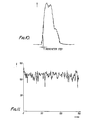
- the digital control offers greater flexibility with the software generated algorithms and replaces the lock in amplifier based analog circuitry. If the laser is deliberately misaligned, the longitudinal mode scan e.g. Fig. 10, shows a triple maximum due to transverse modes. This could be used as a diagnostic for automatic cavity alignment.
- the optics altering the laser characteristics can be controlled continuously, in particular slow thermal drifts are easily compensated, simplifying cavity design and making invar or other pasive stabilization structures obsolete.
- the laser world has not recognizd the wavemetre mode at which the resonator is canned repetitively.
- the number of steps between the adjacent maximum output power of the laser is recorded and/or averaged up until enough date is collected to predict the actual emission wavelength of the passive or active resonator.
- a wedge etalon and accurately record the distance of two or more adjacent transmission and/or reflection maxima with any matrix detector (e.g. a linear array detector).
- any matrix detector e.g. a linear array detector
- This to optimize and influence the beam propagation characteristics such as emitted mode structure (transverse and/or longitudinal), beam-divergence, beam profile. This is especially important for unstable resonators. Last but not least it allows a resonator to be bootstrapped (all components involved to be corrected under puter control).
- TMS third mirror scan
- the trigger for the P.I. and/or main discharge is far more reliable (by using e.g. a thyratron instead of the used spark plug triggered spark gap).
- a thyratron instead of the used spark plug triggered spark gap.
- this method it is in principle possible to isolate the qualities of the position unit,e.g, ball bearing qualities and/or other mechanical jitter effects. Knowing these deficiencies sin a quantified way, it is in principle possible to correct them.
- the absolute frequency was measured approximately with a 2.3 metre long optical Enginering spectrometer (49) using the diffraction properties of a grating with a resulotion of 0.3 0.3 cm- 1 (9GHz).
- the wavelength is found by observing a calibrated carbon plate which lights up on the impact of a C)2 laser pulse.
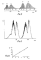
- the linewidth of the MAL was tested with a Fizeau interferometer (51, Fig. 10),a wedged etalon which creates linear fringes which are easier to observe, using linear array detectors, than the circular fringes from a plane parallel etalon.
- the wedge angle was 1 min. and the surface reflectivity was 80%.
- the resulting Fizeau interferometer characteristics are a free spectral range of 3.75 GHz and a finesse of 14 (see Fig. 14).
- a low pressure C)2 laser (Edinburgh Instruments type PL2) was tuned on to the 10R14 SLM transition.
- the output was chopped and used to calibrate the wedge fringes. This output was chopped and passed through a beam expander (55) before the etalon and observed using the array detector (Delta Developments).
- the array detector comprised fifty, 20 u.m wide, pyro-electric elements, the output of which was coupled to a Tektronix 7623 storage oscilloscope.
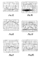
- the two peaks on Fig. 15 enclose the FSK of the wedge to be established a corresponding 30 dots, so the spectral response of the etalon is 125 MHz per dot.
- the resolution of the CW laser linewidth is - 1 MHz opposed to the several dots i.e.-500 MHz.
- FIG. 16 shows that the longitudinal spectrum is wider than the FSR of the wedge etalon and indicates that the axial mode competion alone does not provide the desired linewidth and makes some form of mode selection essential.
- Fig. 17 shows the profile of the beam (approximate Gaussian) and is needed to calibrate the absorption plots. Similar results were obtained when a germanium suppressor mirror was used as the third mirror in the MAL cavity.
- the array detector was first used without the wedge etalon to investigate the beam profile with different apertures in the cavity (see Figures 18 and 19).
- the distance between the laser and the etalon was 0.5 metre.
- Fig. 19 shows the gaussian beam shape in the horizontal plane does not depend on the aperture, although Fig. 18 indicates secondary modes in the vertical plane, due to a bouncing mode from the electrodes. If the array detector was moved further away from the laser (3 metre). the secondary modes could not be observed.
- the FSR of the short MGC cavity was scanned by moving the third mirror with a undirectional increment of 20 DLT steps i.e. 660 MHz.
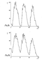
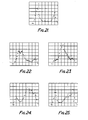
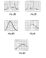
- an array detector output picture freezes the longitudinal mode behaviour of the MAL. This is illustrated in Fig. 20 to Fig. 35 inclusive.
- the narrow output linewidth exhibited in e.g. Fig. 20 and 21 and by contrast the hidden spectrum captures in e.g. Fig. 24 and 31.
- two peaks appear at a separation corresponding to the FSR of the wedge, as with the CW laser (see Fig. 10).
- Minimizing the short cavity length optimizes the mode rejection ration.
- the third mirror scan was represented with respectively 0, 55, 65 and 120 DLT steps.
- the complete laser transmitter system comprises the computer with the Eurocard subrack system, computer disc drives and LDT controller box and optical components such as beam aligners, absorption cell and array detector.
- the tubular rail optical system is supported with three independent tripods (not shown).
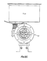
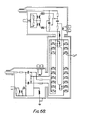
- the MAL, LS with the trigger unit TU (see Fig. 66) on top is supported by one tripod not shown and is isolated with Teflon washers to avoid earth loops with the other electronic equipment such as the HeNe lasers, computer controlled cavity, detectors and optical spectrum analyser.
- Three parallel rails are provided at the front of the laser the support base for the absorption cell vacuum equipment. Alignment equipment runs parallel to the longest rail below the optical axis.
- the detector mounts are covered with a PTFE tape to avoid earth loops between the individual computer driven components.
- the MGC unit dit not need isolation as the connection to the linear Oriel transducer was isolated from the chassis.
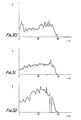
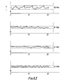
- Figs 43a-b, and c represents the experimental dependence of the ratio E /E obtained using three different beam splitters as the laser frequency is scanned by rotating the cavity grating. From top to bottom of Fig.
- the three beam dividers are a 50/50 % germanium beamsplitter, a polished plane parallel salt flat and and a salt flat of which one side is polished and and the other roughened. It indicates that the multiple reflections produced within the Ge plate (despite the AR coating on one of its surfaces) and the polished salt flat produce interferometric fringes which modulate the output power, since the single sided reflector and opposite sided scatter target were used as a beam divider (BD). This date is significant in that it shows that a BD should never be used in infrared DIAL systems.
- the grating position was changed over 42.5 GHz (50 grating steps) near the 10P14 transmission line.
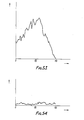
- the spectra shown in Fig.50 to 53 inclusive, were obtained with pure ethylene at pressures of respectively 0.5, 2.5, 5.0 and 7.5 mbar.
- the quantity plotted is the absorbance 1 n(E /E ). All displays show the average of the four values obtained at each grating or third mirror position and compensate for the emply cell tosses. Where an arc occurs (no laser output) all data are rejected. An example of the occurrence of four consecutive arcs is shown in Fig. 52 .
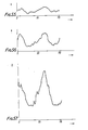
- Figures 54 to 57 inclusive show examples of the high resolution LTMC absorbance scans of ethylene near the 10P14 C02 respectively 0.7, 1.5, 3.5 and 7 mbar.
- the pulse to pulse frequency variation of the MAL has been minimized by repositioning the third mirror using as a reference the absorption signals of ethylene as described above.
- Other locking systems use heterodyne or dither techniques. These are only examples of feedback signals, as are others, e.g. opto acoustic cell(s), opto-valvanic cell(s), (CW and/or pulsed), etalons, optical spectrum analysers, wedge etalons. These signals can be used and provide in part and/or in full the input for the feedback to control a position.
- the term"position transducer is used to predict any absolute or relative position with e.g.
- inductive and/or capacitive and/or optical and/or pressure transducers to act as input to position or move a linear and/or mon-ienear collector with or without puter control in a 3- dimensional or 2 dimensional or 1 dimensional way.
- the frequency locking stability observed here is established to be - 20 MHz, using the edge of the ethylene absorption line at a pressure of 7 mbar (see Fig. 57), which is adequate for DIAL (differential absorption laser) use. Intrapulse contributions (chirp) can be neglected at this level.
- DIAL differential absorption laser
- a Kalman filter based feedback is quite common.
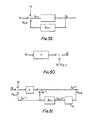
- a system model useful for describing the cavity length or output frequency of the MAL is depicted in Fig. 59.
- the system model is defined with the following equation.
- stated variable k is the frequency and W k a simple form of white noise with a variance given by q which describes the cavity disturbance discussed above.
- U k describes the control input used at various times to change the frequency, which is done in practise by moving the third mirror. In the absence of a control input the equation describes a random walk.
- the laser provides no direct way to feed the above signals into the computer so an absorption cell measurement is used to monitor laser frequency.
- a representation of the measurement model is shown in Fig. 60.
- the measurement of the absorbance ratio before and after the absorption cell can be formulated as follows: where V is the measurement noise due to disturbance such as electronic noise, digitizing noise, and V has a variance denoted by R,H is a constant relating the absorbance to the laser frequency and is obtained from a calibration spectrum such as shown in Fig. 57.
- the frequency estimate X k (+) after a measurement is related, using the standard formula, to the estimate prior to the measurement by where the caret denotes an estimate of the state and the (+) and (-) denote respectively the estimate before and after the control measurement action.
- This deviation indicates when a correction action could be appropriate. i.e. when the difference in the best estimates k (+) - k (-) is more than the standard deviation.
- One powerful feature of the Kalman filtering technique lies in the use of a recursive algorithm. Though the filters output is based upon all data entered since initialization, the data does not have to be saved, minimizing storage requirements.
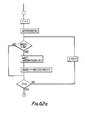
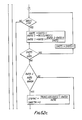
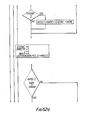
- FIG. 62 A flow diagram for the Kalman third mirror predictor-monitor software is shown in Fig. 62 consisting of past figures 62a to g.
- the previous data shown in Fig. 58a (with no LDT activation) and Fig. 57 give the required input values for the standard deviation of a measurement A T and the absorption change per third mirror step INCRE. Also required are the target value for the absorbance locking RATO and the number of laser shots (N above or in the software; LOCK) for the smoothing of the running measurement average. In the current implementation this selection is initially arbitrary and optimum values are found by trial and error. Clearly this process could be automated if necessary.
- Shots is a counter for the running average. At the start of the program SHOTS is set to unity but is incremented after each shot until it reaches the value of 'LOCK'.
- the estimate of the absorbance is updated and a check is made to find if the difference between the updated and wanted absorbance is significant i.e. is this test difference greater than the standard deviation of the estimate ⁇ T shots.
- the codefile for the complete locking program of which "Execute" forms a part occupies only 22 blocks and data storage requires only 17 blocks for 600 laser shots. Therefore the date from about 15 runs and can be stored on the 280 blocks available on the Apple Pascal floppy disc.
- a Fox-Smith resonator may obtain better results but a three mirror cavity provides the use of a "dual mode cluster", where the frequency separation is - 3GHz.
- a dual mode cluster where the frequency separation is - 3GHz.
- This LTMC demonsrated an example of the computer contro; for the cavity arrangement tried but other resonator configurations could be used since all mirrors are external to the pressure vessel.
- the computer control capability is not only data storage but also monitoring and optimizing on line operating conditions for a particular measurement.
- This computer controlled transmitter system avoids complex dedicated analog circuitry and implements the greater system flexibility that accompanies software control.
- DIAL transmitter functions such as laser optimization, wavelength and (signale and dual) cluster emission frequency selection are verified under computer control.
- Last but not least the similarity of the C02, CO and excimer discharges allow the use of high pressure lasers of this type to be extended to tghe U.V. , visible and other I.R. spectral regions. Detailed changes in some aspects might be needed(e.g. stainless steel high voltage feedthroughs substituted for brass ones), but the modulate setup of this laser has anticipated these requirements.
- tandem resonator and cavity reflectivity Some discussion of tandem resonator and cavity reflectivity is considered now to be relevant.
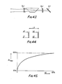
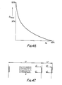
- a single sided, partially reflecting mirror is placed inside and in resonance with the laser cavity (see Fig. 43 ). Optimally the longitudinal modes from the two actively coupled cavities will coincide.
- the mirror grating combination MGC crates a mirror reflectivity maximum that has been used for single mode generation in MAL and TEA lasers.
- This mirror has auxiliary advantages of being loss-free (compared with an etalon), enhancing the effective grating reflectivity and reducing the radiant photon flux on the grating.
- the effective reflectivity of the cavity should be calculated directly by considering the propagating fields within the cavity.
- the mode frequencies are those of the long cavity, while the reflectivity is that of a two mirror cavity composed of an output coupler and a composite mirror, having the (frequency dependent) reflectivity of the tandem resonator made up by the third mirror and grating.
- the compound reflectivity advantages of a MGC will be formulated followed first by consideration of its mode selective effects in the TMC arrangement.
- the MGC is an optical interferometer with a broadband reflector and a rotatable grating, which is mounted at the blazed angle, reflecting the 1 st order of the grating parallel to the incident beam.
- Analysis of the composite system makes use of the description of a perfect beamsplitter in which it is defined by the complex reflectance and transmittance k where
- the index k is used below to characterize the reflecting surface being considered (see Fig. 44).
- a, ⁇ are the phase changes on reflection and transmission, and * indicates the complex conjugate of the wave amplitude.
- O wL 2 /c as the single pass shift;
- w,L 2 and c are the angular radiation frequency, optical path length and the velocity of light.
- tandem interferometric resonators for internal mode selection in laser cavities has the advantages of improved frequency selectivity in comparison with a grating, as well as absence of walk-off effects and insertion loss in comparison with internal etalon. Hence the basic cavity properties like longitudinal mode selectivity and their related resonator lengths are reviewed.
- the MGC therefore adjusts as a reflection etalon in a conventional cavity.
- a LTMC could be designed, to optimize the "system resonance" of the MGC to discriminate and reduce the modes in side the long resonator.
- the grating reflection bandwidth is - 3 GHz in an active environment although, according to eqn. [5.4] it would be expected to be - 12GHz. If we allow for this simply regarding that the grating has a bandwidth of 3 GHz, the reflectivity of the 3 way cavity as a whole can be calculated from eqn [5.29]
- the reflectivity Reff is plotted in Figs. 48, b and c with the reflectivities and resonator lengths which are specified in table 5.1.
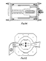
- the laser presently employed comprises a discharge chamber, generally indicated at DSC (Fig. 64).
- the discharge chamber comprises two vessels in the form of stainless steel tubes 1, 3 located co-axially one within the other with outer one being directly earthed (see Figure 69).
- Each of the two tubes is provided with three pairs of diametrically opposed axially directed access slots for high-voltage leads and, e.g. to admit cooled gas, if cooling is used, and also to act as inspection or diagnostic ports; the slots being closable by bolt on covers such as shown a Sic with the slots of the inner tube 1 being aligned with those of the outertube 3.
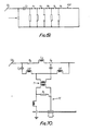
- Fig. 62 shows a pin array PIP the gap (P1 to Ps respectively between opposed pins being - 0.8 mm. Initially the storage capacitor Co is charged to a potential of 65 KV. After the spark-gap is triggered, the voltage rises on the first pin of gap P1. The second pin of gap P1 is at a low potential and the gap breaks down. All pins are loaded with a resistor in this instance of 50K - to form a high impedance for the incremental surge current.
- This simple configuration is an improvement over previously reported sliding spark TEA and MAL lasers.
- the main departure is use of a four sliding spark array of pre-ionised pins PIP in a double sided geometry next to the top and bottom electrodes.
- the tungsten pins are symmetrically displaced with respect to the optical axis.
- Homogeneity of the ionization photons for the preconditioning of the main lasing gap and the lack of obstruction to transverse gas flow are particular improvements in this set-up.
- the arc arrays on each side of the electrode are fed by different capacitors which makes it easier to match the circuit parameters, producing more uniform and critically damped breakdown which both boost U.V. production and avoid erosion of the P.I. pins.
- the pre-ioniser is isolated from the main discharge so the delay between these two discharges can be tuned. Delay times are between 200 nsec to 1.5a sec to provide satisfactory plasma conditions.
- the time interval between the surge currents at successive spark gap breakdowns is less than 1 nsec. For the 33 gaps this results in an overall delay of less than 33 nsec. It has been found that a delay of 75 nsec between the triggers of the P.I. and main bank is satisfactory. The optimal delay between P.I. and main discharge recommended is about 200 nsec. and is in close approximation to what was found.
- the P.I.-unit was improved by introducing capacitors CpP in parallel with the resistors (see Fig. 69) with a value of 180 pF each. Effectively the surge current is forced to charge and discharge these spark peaking capacitors, which extend the photon production.
- Uniformity in pre-ionisation in the directions transverse to the main discharge current flow is more essential than uniformity in the parallel direction.
- Space charge effects distort the local electric field and the ionization rate, but smooth the plasma non-uniformities that develop during discharge initiation and create a uniform discharge.
- Fig. 64 Two ring sets one of which is seen in Fig. 64 and is generally indicated at 5, seal the space between the stainless steel tubes. This space can accommodate cooling liquid to remove excess heat from the gas reservoir, and the ring sets hold the inner vessel in position.
- the discharge chamber is faced at either axial and with end flanges EnF held together by tensile rods TR, to withstand the axial pressure, and in the centre the end flanges carry circular ports which are used to mount Brewster windows or resonator mirrors such as indicated at 7.
- the complete discharge section is seen in Fig. 60 in front elevation.
- the main lasing volume between the main electrodes ME1, ME2 is precondtioned by 4 arrays of pre-ionising, sliding spark gaps assembled as a unit, PIU (see especially Fig.
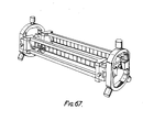
- the P.I. - unit is shown in Fig. 67.
- the unit seen in Fig. 64 shows two of the arrays of pairs of pre-ionised pins PIP mounted on supporting frameworks FW dovetailed into end blocks EB carried by insulating end frames IF mounted, in use, in the inner tube of the discharge chamber.
- the assembly for convenience could be mounted directly on the main electrodes in a self-synchronizing mode.
- a design feature here was the ability to alter the P.I. - electrode distance and optimize the preconditioning of the main electrodes with U.V. photons and to avoid flashover (arcing) between the P.I.
- Fig.65 is a schematic cross-section of the laser chamber showing a possible gas flow system, in which the gas input port GIP, comprising a cooling fan CF, ducts gas into the laser chamber LC over proprietary cooling tubes CT, the flow being laminar and not obstructed by P.I. pins PIP, to flow between the electrodes MEL 1 and 3 and then to exit via the outlet port PO from where it is recirculated back to the input port GIP.
- Additional or alternative cooling means may be provided by circulating coolant through ducts formed in the electrodes themselves.
- the pressure vessel was first tested for pressure and vacuum requirements. Each particular slot section was adapted, to cope with the individual requirements such as a high voltage feed-through (see Fig. 66), after which pressure and vacuum tests were repeated. In the light of the experience gained with this development device, a smaller laser could be constructed for push-button use on a mobile operational I.R. RADAR platform.
- Fig. 66 At the bottom of Fig. 66 the top of the support structure for the high pressure laser is also shown.
- This support structure allows a tubular rail carrying optical elements to be decoupled mechanically and electrically from the main discharge section.
- Top and side dovetails of the rail offer convenient mounting conditions for the optical components such as the external linear three mirror cavity.
- Characterisation at the laser cavity is done by use of a CW - COz discharge section. All optical components and computer cavity control systems used were tested before being implanted in the laser.
- the double screen constituted by the tubes 1, 3 is extended as indicated at DST1 and DST3 respectively in Fig. 69 to house the main discharge circuit DC1 and its trigger TC1 and the pre-ionising discharge circuit DC3 and its trigger TC3 so that these circuits are housed within a double electromagnetic screen.
- the positions DST1 and DST3 may be separately formed and then integral with the discharge chamber.
- Uniformity in pre-ionisation in the directions transverse to the main discharge current flow is more essential than uniformity in the parallel direction.
- Space charge effects distort the local electric field and the ionization rate, but smooth the plasma non-uniformities that develop during discharge initiation and create a uniform discharge.
- the Marx bank (main discharge) and P.I. circuits had approximately a pulse power of 10w at a voltage of 50 KV and currents of 2KA. This is in contrast with the low power networks of current electronic control and diagnostic equipment. Both must share the same wall plug facilities, which leads to earthing problems.
- Sensitive optical detectors with a 10-14- W diagnostic signal (1u. V into 100 (1) make an isolationation factor of 10 22 necessary between power source and real time optical diagnostics. It is also essential to be able to operate computers and real time diagnostics in a nearby vicinity and for the remote sensing equipment to be able to operate the computer controlled optical resonator for automated frequency selection and locking.
- the associated problems of electromagnetic interference in the communication field are similar, but in the present laser system they are distinguished as follows:
- Fig. 70 which illustrates a simplified discharge network DC with trigger circuit TC.
- the trigger circuit comprising a transformer T through which a spark gap SG of the discharge circuit is activated by a pulse from the trigger circuit the trigger circuit providing the earth return for the discharge circuit.
- the plasma load is Lp and Rp representing the inductance and resistance respectively.
- the earth return side is divided in two parts with an inductanc L1 and L2, with L2 assumed to be 1 / 10 of the total inductance L found previously to be about 0.4u. H.
- Rt is a trimming resistor (see Fig. 70) which is initially assumed to be Ot.
- a 10 metre cable with an inductance of 10u. H) is used as a trigger cable.
- This inductance acts in parallel with the circuit inductance of 50 nH, so that a main current of 1.9 KA will induce currents in the order of 10 A in the braid of the coax cable.
- the imposed current transient will result in a voltage spike of 1.0 V on the general earth system.
- This voltage spike is minimized by maximizing the value of the trimming resistor Rt, the circuit is then virtually floating during the discharge with the current only affecting the appropriate conductors, completing a round trip between the capacitor places.
- Ths single earth return lead for the entire circuitry is connected in series with a coil to avoid transient pulses on the earth lead from the P.I. and main discharge current.
- the P.I. pins are grouped in two sections around the main electrode. Each P.I. section is separately connected with a 5 nF capacitor and fired with a common spark gap (SG1)).
- the main electrode Marx bank has two spark gaps (SG2 and SG3) to switch the main discharge current. These are both triggered simultaneously. It was found that the simpler mechanism of triggering SG2 by over-volting caused too much jitter.
Landscapes
- Physics & Mathematics (AREA)
- Electromagnetism (AREA)
- Optics & Photonics (AREA)
- Engineering & Computer Science (AREA)
- Plasma & Fusion (AREA)
- Spectroscopy & Molecular Physics (AREA)
- Chemical & Material Sciences (AREA)
- Life Sciences & Earth Sciences (AREA)
- Health & Medical Sciences (AREA)
- Analytical Chemistry (AREA)
- Biochemistry (AREA)
- General Health & Medical Sciences (AREA)
- General Physics & Mathematics (AREA)
- Immunology (AREA)
- Pathology (AREA)
- Lasers (AREA)
- Investigating Or Analysing Materials By Optical Means (AREA)
- Semiconductor Lasers (AREA)
Applications Claiming Priority (2)
| Application Number | Priority Date | Filing Date | Title |
|---|---|---|---|
| GB8626751 | 1986-11-10 | ||
| GB868626751A GB8626751D0 (en) | 1986-11-10 | 1986-11-10 | Lasers |
Publications (2)
| Publication Number | Publication Date |
|---|---|
| EP0288602A2 true EP0288602A2 (de) | 1988-11-02 |
| EP0288602A3 EP0288602A3 (de) | 1989-09-27 |
Family
ID=10607045
Family Applications (4)
| Application Number | Title | Priority Date | Filing Date |
|---|---|---|---|
| EP87116618A Withdrawn EP0288602A3 (de) | 1986-11-10 | 1987-11-10 | Laser |
| EP87116616A Ceased EP0267592A3 (de) | 1986-11-10 | 1987-11-10 | Laser |
| EP87116617A Withdrawn EP0267593A3 (de) | 1986-11-10 | 1987-11-10 | Laser |
| EP87116615A Ceased EP0270862A3 (de) | 1986-11-10 | 1987-11-10 | Verfahren zur Bestimmung eines Parameters in einem Medium mit Verwendung eines Laserbündels |
Family Applications After (3)
| Application Number | Title | Priority Date | Filing Date |
|---|---|---|---|
| EP87116616A Ceased EP0267592A3 (de) | 1986-11-10 | 1987-11-10 | Laser |
| EP87116617A Withdrawn EP0267593A3 (de) | 1986-11-10 | 1987-11-10 | Laser |
| EP87116615A Ceased EP0270862A3 (de) | 1986-11-10 | 1987-11-10 | Verfahren zur Bestimmung eines Parameters in einem Medium mit Verwendung eines Laserbündels |
Country Status (6)
| Country | Link |
|---|---|
| US (1) | US4866727A (de) |
| EP (4) | EP0288602A3 (de) |
| DK (4) | DK589387A (de) |
| GB (1) | GB8626751D0 (de) |
| IE (1) | IE873020L (de) |
| PT (4) | PT86109A (de) |
Cited By (2)
| Publication number | Priority date | Publication date | Assignee | Title |
|---|---|---|---|---|
| EP0267592A3 (de) * | 1986-11-10 | 1989-09-06 | Commission of the European Communities | Laser |
| US20220260428A1 (en) * | 2021-02-10 | 2022-08-18 | Quantum Valley Ideas Laboratories | Increasing the Measurement Precision of Optical Instrumentation using Kalman-Type Filters |
Families Citing this family (5)
| Publication number | Priority date | Publication date | Assignee | Title |
|---|---|---|---|---|
| US4905250A (en) * | 1987-11-13 | 1990-02-27 | The European Atomic Energy Community | Pre-ionizing electrode arrangement for a gas discharge laser |
| DE3930699C2 (de) * | 1989-09-14 | 1994-02-03 | Perzl Peter | Vorrichtung zur Energieeinkopplung in eine durchströmte elektrische Gasentladung |
| WO1991009298A1 (fr) * | 1989-12-19 | 1991-06-27 | Komi Nauchny Tsentr Uralskogo Otdelenia Akademii Nauk Sssr | Procede et dispositif d'obtention de caracteristiques metriques de parametres spectrochimiques de matieres analysees |
| JP2839339B2 (ja) * | 1990-08-06 | 1998-12-16 | 松下電器産業株式会社 | 直交変換符号化装置および直交変換符号化方法 |
| DE19613805C1 (de) * | 1996-04-06 | 1997-12-11 | Deutsche Forsch Luft Raumfahrt | Verfahren und Einrichtung zur Fernerkundung von Spurengasen |
Family Cites Families (6)
| Publication number | Priority date | Publication date | Assignee | Title |
|---|---|---|---|---|
| GB1577349A (en) * | 1977-03-11 | 1980-10-22 | Andersson H | Method and apparatus for producing laser pulses with high reproducibility |
| DE2824761A1 (de) * | 1977-06-08 | 1978-12-14 | Gen Electric | Entladungserhitzter kupferdampf-laser |
| DE3035730A1 (de) * | 1980-09-22 | 1982-05-13 | Kraftwerk Union AG, 4330 Mülheim | Hochenergielaser des tea-typs mit laser-achsparrallel angeordneten vorionisierungsstaeben |
| FR2553941B1 (fr) * | 1983-10-21 | 1985-12-13 | Commissariat Energie Atomique | Dispositif laser a vapeur metallique |
| US4719641A (en) * | 1985-11-08 | 1988-01-12 | Summit Technology, Inc. | Multiple chamber laser containment system |
| GB8626751D0 (en) * | 1986-11-10 | 1986-12-10 | Dijk J W | Lasers |
-
1986
- 1986-11-10 GB GB868626751A patent/GB8626751D0/en active Pending
-
1987
- 1987-11-10 EP EP87116618A patent/EP0288602A3/de not_active Withdrawn
- 1987-11-10 PT PT86109A patent/PT86109A/pt not_active Application Discontinuation
- 1987-11-10 DK DK589387A patent/DK589387A/da not_active Application Discontinuation
- 1987-11-10 EP EP87116616A patent/EP0267592A3/de not_active Ceased
- 1987-11-10 DK DK589287A patent/DK589287A/da not_active Application Discontinuation
- 1987-11-10 PT PT86108A patent/PT86108A/pt not_active Application Discontinuation
- 1987-11-10 IE IE873020A patent/IE873020L/xx unknown
- 1987-11-10 EP EP87116617A patent/EP0267593A3/de not_active Withdrawn
- 1987-11-10 DK DK589087A patent/DK589087A/da not_active Application Discontinuation
- 1987-11-10 PT PT86107A patent/PT86107A/pt not_active Application Discontinuation
- 1987-11-10 DK DK589187A patent/DK589187A/da not_active Application Discontinuation
- 1987-11-10 PT PT86106A patent/PT86106A/pt not_active Application Discontinuation
- 1987-11-10 EP EP87116615A patent/EP0270862A3/de not_active Ceased
- 1987-11-13 US US07/120,158 patent/US4866727A/en not_active Expired - Fee Related
Non-Patent Citations (3)
| Title |
|---|
| APPLIED OPTICS, vol. 23, no. 24, December 1984, pages 4465-4468, New York, US; M.G. LITTMAN et al.: "Single-mode pulsed tunable dye laser" * |
| JOURN. OF PHYSICS E. SCIENT. INSTR., vol. 12, no. 10, October 1979, pages 915-918, The Institute of Physics; H.L. SELZLE et al.: "Absolute wavelength scan of a laser with microprocessor control" * |
| JOURNAL OF PHYSICS D. APLLIED PHYSICS, vol. 19, no. 3, March 1986, pages 417-425, The Institute of Physics, Bristol, GB; L.M. KUKREJA et al.: "On obtaining well defined transverse modes and selective line tuning of a long cw CO2 laser" * |
Cited By (4)
| Publication number | Priority date | Publication date | Assignee | Title |
|---|---|---|---|---|
| EP0267592A3 (de) * | 1986-11-10 | 1989-09-06 | Commission of the European Communities | Laser |
| EP0267593A3 (de) * | 1986-11-10 | 1989-09-27 | Commission of the European Communities | Laser |
| US20220260428A1 (en) * | 2021-02-10 | 2022-08-18 | Quantum Valley Ideas Laboratories | Increasing the Measurement Precision of Optical Instrumentation using Kalman-Type Filters |
| US11435234B1 (en) * | 2021-02-10 | 2022-09-06 | Quantum Valley Ideas Laboratories | Increasing the measurement precision of optical instrumentation using Kalman-type filters |
Also Published As
| Publication number | Publication date |
|---|---|
| PT86106A (pt) | 1988-12-15 |
| DK589287D0 (da) | 1987-11-10 |
| PT86109A (pt) | 1988-12-15 |
| EP0267592A2 (de) | 1988-05-18 |
| EP0267592A3 (de) | 1989-09-06 |
| IE873020L (en) | 1988-05-10 |
| DK589187A (da) | 1988-05-11 |
| EP0270862A3 (de) | 1990-01-17 |
| PT86108A (pt) | 1988-12-15 |
| DK589387D0 (da) | 1987-11-10 |
| EP0270862A2 (de) | 1988-06-15 |
| PT86107A (pt) | 1988-12-15 |
| GB8626751D0 (en) | 1986-12-10 |
| DK589087A (da) | 1988-05-11 |
| EP0267593A2 (de) | 1988-05-18 |
| DK589287A (da) | 1988-05-11 |
| DK589187D0 (da) | 1987-11-10 |
| DK589387A (da) | 1988-05-11 |
| EP0267593A3 (de) | 1989-09-27 |
| EP0288602A3 (de) | 1989-09-27 |
| DK589087D0 (da) | 1987-11-10 |
| US4866727A (en) | 1989-09-12 |
Similar Documents
| Publication | Publication Date | Title |
|---|---|---|
| US4847854A (en) | Lasers | |
| Bruneau et al. | Airborne lidar LEANDRE II for water-vapor profiling in the troposphere. I. System description | |
| Romanini et al. | Diode laser cavity ring down spectroscopy | |
| CN100508308C (zh) | 带有波长控制的注入种子的f2激光器 | |
| Moreno et al. | Traveling wave excitation and amplification of neon-like germanium 3p–3s transitions | |
| US20020186741A1 (en) | Very narrow band excimer or molecular fluorine laser | |
| Cavallo et al. | Twenty‐channel grating polychromator for millimeter wave plasma emission measurements | |
| US20020186739A1 (en) | Injection seeded F2 laser with wavelength control | |
| Billardon et al. | Recent results of the ACO storage ring FEL experiment | |
| Austin et al. | Improved operation of the Michelson interferometer electron cyclotron emission diagnostic on DIII-D | |
| Harris et al. | Acoustic phenomena associated with a TEA laser discharge | |
| Szarmes et al. | Mode control on short-pulse FELs using a Michelson-mirror resonator | |
| Friss et al. | Cavity enhanced Thomson scattering for diagnostics of weakly ionized discharges | |
| Knittel et al. | High-pressure single-mode CO 2 laser with picosecond plasma shutter | |
| Ferianis et al. | How the optical timing system, the longitudinal diagnostics and the associated feedback systems provide femtosecond stable operation at the FERMI free electron laser | |
| Barbini et al. | Line tunable TEA CO2 laser using SFUR configuration | |
| Augustinus et al. | Computer control of frequency tunable CO2 lasers | |
| Litzenberger et al. | Direct bandwidth and polarization control of an XeF unstable resonator laser | |
| Kochubeĭ et al. | High-pressure tunable atomic gas lasers | |
| Jaroszynski et al. | Data acquisition and optical diagnostic systems for the UK FEL | |
| Lumpkin et al. | Electron beam bunch length characterizations using incoherent and coherent transition radiation on the APS SASE FEL project | |
| Friss et al. | Towards a Cavity Enhanced Thomson Scattering Diagnostic for Electric Propulsion Research | |
| Turner et al. | uv‐laser photofragmentation instrument: Multiphoton ionization and dissociation of small molecules | |
| Friss et al. | Fiber Coupled Cavity Enhanced Thomson Scattering Diagnostic for Use in Electric Propulsion Facilities | |
| Rashedi et al. | A highly stable and tunable extended cavity diode laser |
Legal Events
| Date | Code | Title | Description |
|---|---|---|---|
| PUAI | Public reference made under article 153(3) epc to a published international application that has entered the european phase |
Free format text: ORIGINAL CODE: 0009012 |
|
| AK | Designated contracting states |
Kind code of ref document: A2 Designated state(s): AT BE CH DE ES FR GB GR IT LI LU NL SE |
|
| PUAL | Search report despatched |
Free format text: ORIGINAL CODE: 0009013 |
|
| AK | Designated contracting states |
Kind code of ref document: A3 Designated state(s): AT BE CH DE ES FR GB GR IT LI LU NL SE |
|
| 17P | Request for examination filed |
Effective date: 19891121 |
|
| 17Q | First examination report despatched |
Effective date: 19920313 |
|
| STAA | Information on the status of an ep patent application or granted ep patent |
Free format text: STATUS: THE APPLICATION IS DEEMED TO BE WITHDRAWN |
|
| 18D | Application deemed to be withdrawn |
Effective date: 19920724 |
|
| RIN1 | Information on inventor provided before grant (corrected) |
Inventor name: VAN DIJK, JOHANNES WILHELMUS |