EP0288635A2 - Ensemble à buse - Google Patents
Ensemble à buse Download PDFInfo
- Publication number
- EP0288635A2 EP0288635A2 EP87308099A EP87308099A EP0288635A2 EP 0288635 A2 EP0288635 A2 EP 0288635A2 EP 87308099 A EP87308099 A EP 87308099A EP 87308099 A EP87308099 A EP 87308099A EP 0288635 A2 EP0288635 A2 EP 0288635A2
- Authority
- EP
- European Patent Office
- Prior art keywords
- nozzle
- fluid passage
- fluid
- nozzle assembly
- control valve
- Prior art date
- Legal status (The legal status is an assumption and is not a legal conclusion. Google has not performed a legal analysis and makes no representation as to the accuracy of the status listed.)
- Withdrawn
Links
Images

Classifications
-
- B—PERFORMING OPERATIONS; TRANSPORTING
- B05—SPRAYING OR ATOMISING IN GENERAL; APPLYING FLUENT MATERIALS TO SURFACES, IN GENERAL
- B05B—SPRAYING APPARATUS; ATOMISING APPARATUS; NOZZLES
- B05B1/00—Nozzles, spray heads or other outlets, with or without auxiliary devices such as valves, heating means
- B05B1/34—Nozzles, spray heads or other outlets, with or without auxiliary devices such as valves, heating means designed to influence the nature of flow of the liquid or other fluent material, e.g. to produce swirl
- B05B1/3405—Nozzles, spray heads or other outlets, with or without auxiliary devices such as valves, heating means designed to influence the nature of flow of the liquid or other fluent material, e.g. to produce swirl to produce swirl
- B05B1/341—Nozzles, spray heads or other outlets, with or without auxiliary devices such as valves, heating means designed to influence the nature of flow of the liquid or other fluent material, e.g. to produce swirl to produce swirl before discharging the liquid or other fluent material, e.g. in a swirl chamber upstream the spray outlet
- B05B1/3421—Nozzles, spray heads or other outlets, with or without auxiliary devices such as valves, heating means designed to influence the nature of flow of the liquid or other fluent material, e.g. to produce swirl to produce swirl before discharging the liquid or other fluent material, e.g. in a swirl chamber upstream the spray outlet with channels emerging substantially tangentially in the swirl chamber
- B05B1/3426—Nozzles, spray heads or other outlets, with or without auxiliary devices such as valves, heating means designed to influence the nature of flow of the liquid or other fluent material, e.g. to produce swirl to produce swirl before discharging the liquid or other fluent material, e.g. in a swirl chamber upstream the spray outlet with channels emerging substantially tangentially in the swirl chamber the channels emerging in the swirl chamber perpendicularly to the outlet axis
-
- B—PERFORMING OPERATIONS; TRANSPORTING
- B29—WORKING OF PLASTICS; WORKING OF SUBSTANCES IN A PLASTIC STATE IN GENERAL
- B29B—PREPARATION OR PRETREATMENT OF THE MATERIAL TO BE SHAPED; MAKING GRANULES OR PREFORMS; RECOVERY OF PLASTICS OR OTHER CONSTITUENTS OF WASTE MATERIAL CONTAINING PLASTICS
- B29B7/00—Mixing; Kneading
- B29B7/74—Mixing; Kneading using other mixers or combinations of mixers, e.g. of dissimilar mixers ; Plant
- B29B7/76—Mixers with stream-impingement mixing head
- B29B7/7631—Parts; Accessories
Definitions
- the present invention relates to a nozzle assembly and more precisely it relates to a nozzle assembly which can control the ejection of the fluid.
- the nozzle accelerates the highly pressurized fluid to convert the pressure of the fluid to a kinetic energy in order to create a flow of fluid having a high velocity or a diffused flow of fluid.
- a nozzle such as a needle type of nozzle, in which the conversion of the pressure of the fluid to the kinematic energy, namely the acceleration and the diffusion of the fluid flow can be controlled is also known.
- this type of nozzle has a needle which moves in a nozzle port to control the sectional area of the nozzle port thereby to vary the ejection state of the fluid.
- the control is, however, mainly directed to the flow rate of the fluid. In other words, it is very difficult for the known nozzle to control the diffusion angle of the flow which varies in accordance with the change of the flow rate.
- a mixing apparatus of synthetic resin containing a plurality of resin components such as polyurethane resin or the like
- two nozzles are opposed to eject reactive resin components at a high speed, so that the ejected components come into collision with each other, whereby the synthetic resin is stirred and mixed.
- the known needle type of nozzle can not satisfy the requirements mentioned above, since it is very difficult to precisely control both the flow rate and the diffusion angle which varies in accordance with the change of the flow rate, as mentioned before.
- the needle type of nozzle has another drawback that the nozzle port a cross sectional area of which is controlled by a movable needle located at the center of the nozzle port can be easily clogged with a foreign matter, such as dust or other substances which have been accidentally mixed, resulting in an disturbance of the flow to be ejected from the nozzle port.
- the primary object of the present invention is to eliminate the above mentioned drawbacks by providing a novel nozzle assembly which can eject either a diffused fluid in the form of a cone or a sprayed fluid.
- Another object of the present invention is to provide a nozzle assembly which can control the diffusion angle of the fluid when the ejection speed or viscosity of the fluid to be ejected vary.
- a nozzle assembly having a nozzle body which has a fluid passage with a conical nozzle port at the front end of the fluid passage, said nozzle body being provided, on its outer periphery, with at least one inlet port which opens into the fluid passage in the tangential direction, and a control valve which is provided in the fluid passage so as to move forward and backward to control the sectional area of the inlet port.
- the fluid enters the fluid passage in the tangential directions through the inlet port provided on the outer periphery of the nozzle body.
- the fluid in the fluid passage flows forward along the inner peripheral wall of the fluid passage while swirling in the fluid passage, and is ejected from the conical nozzle port.
- the flow speed of the fluid is accelerated by the conical nozzle port.
- the control valve adjusts the sectional area of the inlet port of the nozzle body in order to vary the swirl speed of the fluid in the fluid passage, thereby to control the ejection conditions of the fluid, such as a diffusion speed or a diffusion angle, of the fluid, in accordance with the property of the fluid or if needed.
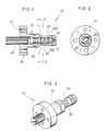
- the nozzle assembly 10 has a nozzle body 15 which has a fluid passage 11 which is provided on its front end with a conical nozzle port 13. On the outer periphery of the nozzle body 15 are provided two inlet ports 20 and 25 which open into the fluid passage 11 in the tangential direction thereto.
- the nozzle assembly 10 has a control valve 30 which is provided in the fluid passage 11 so as to move forward and backward to control the cross sectional areas of the inlet ports 20 and 25.
- Numerals 16 and 17 designate a flange and mounting holes, respectively, so that the nozzle assembly 10 can be secured to an associated device (not shown).
- the inlet ports 20 and 25 extend in the tangetial directions to the fluid passage 15 when viewed in a cross section of the fluid passage, as can be seen from Fig. 2, so that the fluid which enters the fluid passage through the inlet ports 20 and 25 flows along the circular wall of the fluid passage which has a circular cross section while swirling, as shown by arrows C in Figs. 1 and 2.
- two inlet ports 20 and 25 are diametrically opposed to effectively swirl the fluid flow.
- the control valve 30 controls the cross sectional areas of the inlet ports 20 and 25.
- the control valve 30 is actuated by a threaded member 40 which is screwed in the nozzle body 15 at the rear end of the latter.
- the adjusting screw (threaded member) 40 adjusts the axial displacement of the control valve 30 to control the cross sectional areas of the inlet ports 20 and 25.
- the inlet ports 20 and 25 have different axial lengths in the direction of the movement of the control valve 30, so that they have front ends 20E and 25E at different axial positions. This enables the control valve 30 to control the cross sectional areas of the inlet ports 20 and 25 more precisely with various modes.
- Fig. 4 shows a mixing apparatus for polyurethane resin, in which the nozzle assemblies of the present invention mentioned above are incorporated.
- the mixing apparatus has a body block 50 which has therein a mixing chamber 51.
- Two nozzle assemblies 10A and 10B according to the present invention are located on the opposite sides of the mixing chamber 51, so that the nozzle ports 13A and 13B of the nozzle assemblies 10A and 10B are diametrically opposed to each other.
- Reactive resin components are ejected from the respective nozzle ports 13A and 13B into the mixing chamber 51, so that the resin components come into collision with each other and are mixed in the mixing chamber 51.
- the mixture is then introduced into a molding cavity (not shown).
- Numerals 53A and 53B designate introduction passages through which the respective resin components are introduced into the nozzle assemblies 10A and 10B.
- the introduction passages 53A and 53B which are formed in the body block 50 have connecting portions 55A and 55B which are connected to the inlet ports 20A, 20B etc. of the nozzle assemblies 10A and 10B.
- the resin components ejected into the mixing chamber 51 from the nozzle ports 13A and 13B of the nozzle assemblies 10A and 10B are conically diffused or sprayed to come into collision with each other at a high speed to be mixed.
- the kinetic momenta of the resin componets can be controlled by the control valves 30A and 30B which move forward and backward in the fluid passages of the nozzle assemblies 10A and 10B to control the cross sectional areas of the inlet ports 20A, 25A (20B, 25B) depending on the properties of the resin components.
- the inlet ports extend in the tangential directions of the fluid passage so as to make a swirl of the fluid, it is ensured that the fluid is conically diffused or sprayed. Furthermore, since the control valve which is provided in the fluid passage so as to axially move forward and backward to control the sectional areas of the inlet ports, the swirl speed of the fluid in the fluid passage can be controlled and accordingly, the ejection state of the fluid, i.e. the diffusion speed and the diffusion angle of the fluid, etc. can be effectively controlled in accordance with the properties of the fluid. In particular, even when the viscosity of the fluid or the ejection speed of the fluid varies, the fluid can be diffused in a desired state by the control valve.
Landscapes
- Engineering & Computer Science (AREA)
- Mechanical Engineering (AREA)
- Nozzles (AREA)
- Processing And Handling Of Plastics And Other Materials For Molding In General (AREA)
- Casting Or Compression Moulding Of Plastics Or The Like (AREA)
- Injection Moulding Of Plastics Or The Like (AREA)
Applications Claiming Priority (2)
| Application Number | Priority Date | Filing Date | Title |
|---|---|---|---|
| JP106009/87 | 1987-04-28 | ||
| JP10600987A JPS63270565A (ja) | 1987-04-28 | 1987-04-28 | ノズル |
Publications (2)
| Publication Number | Publication Date |
|---|---|
| EP0288635A2 true EP0288635A2 (fr) | 1988-11-02 |
| EP0288635A3 EP0288635A3 (fr) | 1989-07-12 |
Family
ID=14422674
Family Applications (1)
| Application Number | Title | Priority Date | Filing Date |
|---|---|---|---|
| EP87308099A Withdrawn EP0288635A3 (fr) | 1987-04-28 | 1987-09-14 | Ensemble à buse |
Country Status (2)
| Country | Link |
|---|---|
| EP (1) | EP0288635A3 (fr) |
| JP (1) | JPS63270565A (fr) |
Cited By (1)
| Publication number | Priority date | Publication date | Assignee | Title |
|---|---|---|---|---|
| WO2006069849A1 (fr) * | 2004-12-23 | 2006-07-06 | Krauss-Maffei Kunststofftechnik Gmbh | Tete de melange a manchon d'etancheite |
Families Citing this family (1)
| Publication number | Priority date | Publication date | Assignee | Title |
|---|---|---|---|---|
| EP1322425A4 (fr) * | 2000-07-06 | 2006-12-20 | Lancer Partnership Ltd | Procede et appareil de traitement de fluides |
Family Cites Families (6)
| Publication number | Priority date | Publication date | Assignee | Title |
|---|---|---|---|---|
| DE301230C (fr) * | ||||
| BE451641A (fr) * | 1943-07-27 | |||
| FR948056A (fr) * | 1947-05-30 | 1949-07-21 | Pulvérisateurs mécaniques de liquides | |
| FR1376485A (fr) * | 1963-01-17 | 1964-10-31 | Buse d'admission pour mélangeurs | |
| US3920187A (en) * | 1974-05-24 | 1975-11-18 | Porta Test Mfg | Spray head |
| EP0096493B1 (fr) * | 1982-05-25 | 1987-08-19 | Johnson Matthey Public Limited Company | Four à arc à plasma |
-
1987
- 1987-04-28 JP JP10600987A patent/JPS63270565A/ja active Pending
- 1987-09-14 EP EP87308099A patent/EP0288635A3/fr not_active Withdrawn
Cited By (1)
| Publication number | Priority date | Publication date | Assignee | Title |
|---|---|---|---|---|
| WO2006069849A1 (fr) * | 2004-12-23 | 2006-07-06 | Krauss-Maffei Kunststofftechnik Gmbh | Tete de melange a manchon d'etancheite |
Also Published As
| Publication number | Publication date |
|---|---|
| JPS63270565A (ja) | 1988-11-08 |
| EP0288635A3 (fr) | 1989-07-12 |
Similar Documents
| Publication | Publication Date | Title |
|---|---|---|
| KR950003762B1 (ko) | 연료분사 밸브 | |
| CA1209104A (fr) | Dispositif melangeur-debiteur des composantes d'un contenant compartimente | |
| US3790086A (en) | Atomizing nozzle | |
| CA2017896C (fr) | Robinet conditionneur de vapeur | |
| EP1569756B1 (fr) | Douche avec alimentation en air | |
| JP3497532B2 (ja) | 気体−液体混合装置 | |
| US4595143A (en) | Air swirl nozzle | |
| EP0748656B1 (fr) | Ensemble de buse de moussage/pulvérisation pour pulvérisateurs à gâchette | |
| DE10304386B4 (de) | Doppelfluid-Verwirbelungsdüse mit selbstreinigendem Zapfen | |
| CA2160964C (fr) | Atomiseur a diagramme d'atomisation variable | |
| EP0077380B1 (fr) | Tete melangeuse de moulage par injection a reaction (rim) avec recyclage sous haute pression | |
| EP3087226B1 (fr) | Unité d'insertion sanitaire | |
| GB2309180A (en) | Spray nozzle for aerating liquids | |
| US4655395A (en) | Adjustable conical atomizer | |
| GB2075369A (en) | Air-efficient atomizing spray nozzle | |
| JPS63104679A (ja) | 液体の混合吐出又は噴出方法とその装置 | |
| US5901908A (en) | Spray nozzle for fluid deposition | |
| DE19758557A1 (de) | Niederdruckzerstäubungsvorrichtung mit mehreren benachbarten Zweistoffdüsen | |
| GB2164864A (en) | Movable chamber mixing head | |
| GB2078548A (en) | Solid-cone nozzle for spraying liquid | |
| US4796547A (en) | Fine particle dispersing device for mixing reactant with combustion gas | |
| US4503014A (en) | Mixing head | |
| US4422476A (en) | Fluidic control devices | |
| EP0060540B1 (fr) | Dispositif pour la formation d'une pluralité de jets d'eau aérée, en particulier pomme de douche | |
| US2774629A (en) | Variable area fuel nozzles |
Legal Events
| Date | Code | Title | Description |
|---|---|---|---|
| PUAI | Public reference made under article 153(3) epc to a published international application that has entered the european phase |
Free format text: ORIGINAL CODE: 0009012 |
|
| AK | Designated contracting states |
Kind code of ref document: A2 Designated state(s): DE FR GB IT |
|
| PUAL | Search report despatched |
Free format text: ORIGINAL CODE: 0009013 |
|
| AK | Designated contracting states |
Kind code of ref document: A3 Designated state(s): DE FR GB IT |
|
| STAA | Information on the status of an ep patent application or granted ep patent |
Free format text: STATUS: THE APPLICATION IS DEEMED TO BE WITHDRAWN |
|
| 18D | Application deemed to be withdrawn |
Effective date: 19900113 |
|
| RIN1 | Information on inventor provided before grant (corrected) |
Inventor name: TAWADA, TAKESHI |