EP0288700A1 - Dispositif pour transporter et calibrer des feuilles pour des machines à traitement de feuilles - Google Patents
Dispositif pour transporter et calibrer des feuilles pour des machines à traitement de feuilles Download PDFInfo
- Publication number
- EP0288700A1 EP0288700A1 EP88103791A EP88103791A EP0288700A1 EP 0288700 A1 EP0288700 A1 EP 0288700A1 EP 88103791 A EP88103791 A EP 88103791A EP 88103791 A EP88103791 A EP 88103791A EP 0288700 A1 EP0288700 A1 EP 0288700A1
- Authority
- EP
- European Patent Office
- Prior art keywords
- ball
- particular according
- sheet
- friction
- force transmission
- Prior art date
- Legal status (The legal status is an assumption and is not a legal conclusion. Google has not performed a legal analysis and makes no representation as to the accuracy of the status listed.)
- Granted
Links
- 238000012545 processing Methods 0.000 title claims description 4
- 238000007639 printing Methods 0.000 claims abstract description 5
- 230000005540 biological transmission Effects 0.000 claims description 21
- 238000007664 blowing Methods 0.000 claims description 4
- 238000002347 injection Methods 0.000 claims description 2
- 239000007924 injection Substances 0.000 claims description 2
- 239000002184 metal Substances 0.000 claims description 2
- 230000032258 transport Effects 0.000 description 6
- 238000013461 design Methods 0.000 description 2
- 239000000463 material Substances 0.000 description 2
- 230000004888 barrier function Effects 0.000 description 1
- 238000010276 construction Methods 0.000 description 1
- 230000001419 dependent effect Effects 0.000 description 1
- 238000011161 development Methods 0.000 description 1
- 230000018109 developmental process Effects 0.000 description 1
- 238000006073 displacement reaction Methods 0.000 description 1
- 238000005516 engineering process Methods 0.000 description 1
- 230000002349 favourable effect Effects 0.000 description 1
- 239000002783 friction material Substances 0.000 description 1
- 238000003780 insertion Methods 0.000 description 1
- 230000037431 insertion Effects 0.000 description 1
- 238000009434 installation Methods 0.000 description 1
- 238000005259 measurement Methods 0.000 description 1
- 230000003287 optical effect Effects 0.000 description 1
- 239000000243 solution Substances 0.000 description 1
- 230000003068 static effect Effects 0.000 description 1
Images


Classifications
-
- B—PERFORMING OPERATIONS; TRANSPORTING
- B65—CONVEYING; PACKING; STORING; HANDLING THIN OR FILAMENTARY MATERIAL
- B65H—HANDLING THIN OR FILAMENTARY MATERIAL, e.g. SHEETS, WEBS, CABLES
- B65H9/00—Registering, e.g. orientating, articles; Devices therefor
- B65H9/16—Inclined tape, roller, or like article-forwarding side registers
- B65H9/166—Roller
-
- B—PERFORMING OPERATIONS; TRANSPORTING
- B41—PRINTING; LINING MACHINES; TYPEWRITERS; STAMPS
- B41F—PRINTING MACHINES OR PRESSES
- B41F21/00—Devices for conveying sheets through printing apparatus or machines
- B41F21/12—Adjusting leading edges, e.g. front stops
-
- B—PERFORMING OPERATIONS; TRANSPORTING
- B41—PRINTING; LINING MACHINES; TYPEWRITERS; STAMPS
- B41F—PRINTING MACHINES OR PRESSES
- B41F21/00—Devices for conveying sheets through printing apparatus or machines
- B41F21/14—Adjusting lateral edges, e.g. side stops
-
- B—PERFORMING OPERATIONS; TRANSPORTING
- B65—CONVEYING; PACKING; STORING; HANDLING THIN OR FILAMENTARY MATERIAL
- B65H—HANDLING THIN OR FILAMENTARY MATERIAL, e.g. SHEETS, WEBS, CABLES
- B65H9/00—Registering, e.g. orientating, articles; Devices therefor
- B65H9/10—Pusher and like movable registers; Pusher or gripper devices which move articles into registered position
- B65H9/103—Pusher and like movable registers; Pusher or gripper devices which move articles into registered position acting by friction or suction on the article for pushing or pulling it into registered position, e.g. against a stop
- B65H9/105—Pusher and like movable registers; Pusher or gripper devices which move articles into registered position acting by friction or suction on the article for pushing or pulling it into registered position, e.g. against a stop using suction means
Definitions
- the invention relates to a device for conveying and aligning sheets in sheet processing machines, in particular sheet printing machines, according to the preamble of the main claim.
- a device of the type mentioned wherein a ball-bearing cage is arranged above a sheet support table at a distance from it.
- the cage opening which is circular in cross section, has a larger diameter than the ball.
- the cage height and the distance of the cage from the sheet support table are dimensioned such that the ball projects beyond the cage opening on both sides.
- the object of the invention is based on the object of designing a generic device of simple construction and advantageous in terms of control technology in such a way that clearly defined conveying directions can be imposed on the arc by the ball.
- the angle of the diagonal movement can be varied by an independently provided speed control. It is therefore even possible that the side and front marks of a table are reached simultaneously by the corresponding sheet edges. For example, the angle of the diagonal conveyance of the sheet is 45 ° at the same speed of the corresponding drives.
- the alignment of the sheet can also be done without placing the table on the table, specifically by means of computer control of the drives based on, for example, optical scanning of the sheet. Since the spherical cap of the ball engages on the underside of the arch, greater forces can never act on the arch itself, which could damage it during transport. The projection of the spherical cap over the surface of the table can be used to vary the frictional connection between the arch and the spherical cap.
- both friction wheels must be selected to be the same size.
- the friction wheel drives can be inserted into the overall structure of the device in a space-saving manner.
- the one friction force transmission point lies in the plane of the axis of rotation of the other friction wheel. It proves to be optimal It turns out that the plane through the frictional force transmission points runs through the center of the ball and parallel to the conveying plane. Slip between the ball and friction wheels is largely counteracted. The corresponding movements of the frictional force transmission points are therefore transmitted precisely to the arch via the ball.
- An increase in the friction between the spherical cap and the underside of the arch is increased by the suction gap provided between the ball and the feed table through-hole, which in turn is connected to the vacuum source.
- the friction between the bow and the spherical cap can be varied by appropriately dimensioning the negative pressure.
- one or more balls can be assigned to the table, the speeds of the friction wheel drives being controlled in such a way that the sheet is gently transported to the alignment position in a predetermined way.
- Another possibility, or one that can be used in combination with it, of varying the friction between the spherical cap and the bow is to provide the ball surface with suction holes and to connect the inside of the ball to the vacuum source.
- the ball itself can be formed from a wide variety of materials, preferably sintered metal, through which the ball receives a porous wall. A protrusion of approx.1.5mm from the calotte over the surface of the disk is sufficient to carry the bow along.
- a particularly technically favorable solution to connect the annular gap and the inside of the ball to the vacuum source This is to be seen in accommodating the ball, including its storage, in the vacuum chamber. These or several if necessary are then integrated into the table.
- the air-blowing openings arranged at a distance from the ball are used. In this way it is possible to transport the sheet like an air cushion. The blown air is dimensioned so that the suction force in the area of the spherical cap is not canceled.
- bearing balls are sufficient, which - if necessary together with the drive wheels - add up to a three-dimensional bearing.
- the arrangement of the bearing balls is preferably such that the ball rests on a lower bearing ball, while further bearing balls act on the upper half of the ball and thus realize all-round, play-free storage.
- the transport of the sheet can also be favored by the fact that the spherical surface is provided with a corresponding friction lining, which may be matched to the sheet material. The arch is optimally protected, especially when it is aligned without being hit.
- the alignment movement of the sheet or the insertion of the friction wheel drives can, for. B. only happen when the sheet leading edge passes a scanner.
- the frictional force transmission points can also be used by lying opposite the bearing balls, so that a bearing ball can possibly be dispensed with in their area.
- at least three bearing balls must always be provided in order to maintain a defined position of the ball.
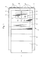
- the sheets in the transport direction x successively and in scales on a table 1, z. B. a feed table of a sheet printing machine, or another sheet processing machine.
- the feed table 1 On its front narrow edge 2, the feed table 1 is equipped with a plurality of front marks 3 projecting beyond the sheet table surface.
- the feed table 1 has in its front region 4 on its one longitudinal edge 5 a side mark 6 which also projects beyond the feed table surface.
- the alignment according to the invention is not dependent on the existence of such marks.
- a device 7 for applying the sheets A, B, C, etc. is assigned to the front area 4 of the feed table 1. 1, the device 7 has two box-like vacuum chambers 8, 9 lying at the same height. The same are sat in mirror image.
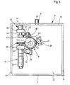
- Each vacuum chamber 8, 9 is equipped with a bottom 10, at right angles to this aligned side walls 11, 12, 13, 14 and with a cover 15 placed on the side walls, the latter being inserted into a contour-accurate recess 16 of the feed table 1 and accordingly a part represents the same.
- One side wall 13 carries a connecting piece 17 which can be connected to a vacuum source via a line (not shown).
- a ball 18 rotates in all directions about its fixed center M by means of four bearing balls 19, 20, 21, 22 placed on the spherical surface.
- the latter are seated in blocks 23, 24, 25, 26 attached to the base 10.
- the bearing ball 19 rotatable in the lug 23 extends perpendicularly below the center M of the ball 18.
- the remaining three bearing balls 20, 21, 22 are provided with the same circumferential distribution as the ball, lie on a common horizontal plane and rest on the spherical surface of the upper half of the ball with positioning of the ball 18.
- the lugs and the bearing balls are arranged so that the ball 18 is kept free of play.
- the ball 18 projects over the feed table 1 with a dome 27 projecting above it.
- the protrusion is approximately 1.5 mm.
- a passage hole 28 is provided in the vacuum chamber cover 15.
- a suction gap 29 is formed between the through hole 28 and the spherical surface lying at the same height 3, so that the sheet A overflowing the ball 18 according to FIG. 3 passes through this suction gap 29 in increased friction to the calotte 27 of the ball 18 as a result of the negative pressure.
- the ball 18 is driven by two friction wheel drives 30, 31 which are at right angles to one another.
- the drive axis y of the friction wheel drive 30 runs parallel to the side mark 6, while the drive axis z of the other friction wheel drive 31 is aligned parallel to the front marks 3. Furthermore, the drive axes y and z extend at the same height of the center M of the ball and run parallel to the conveying plane of the arc.
- Each friction wheel drive 30, 31 has a friction wheel 32, 33 which is arranged at the center of the ball and is set in rotation by a DC motor 34, 35.
- friction force transmission points S1 and S2 are formed between ball 18 and the friction wheels in such a way that in each case one friction force transmission point lies in the plane of the axis of rotation of the other friction wheel.
- the DC motors 34, 35 in turn are seated in bearing blocks 36, 37 starting from the vacuum chamber floor 10.
- the diameters of the friction wheels 32, 33 are of the same size.
- the friction wheels 32, 33 are provided on their circumference with a friction lining in order to enable the ball 18 to be taken along without slipping.
- the feed table 1 can, for. B. a scanning device 38 illustrated in dash-dotted lines in FIG. 1.
- the same can be designed, for example, as a light barrier and serves to switch on the friction wheel drives, the latter of which can be speed-controlled independently of one another via a computer (not shown).
- the running arc A is e.g. in its position illustrated in full lines in FIG. 1 on the leading edge 39 of the sheet is detected by the scanning device.
- the friction wheel drives 30, 31 are switched directly or via a computer. 2, if the friction wheels 32, 33 rotate at the same speed, the plane of rotation of the ball 18 extends at an angle of 45 ° to the sheet transport direction x.
- the bow A is accordingly moved in the diagonal direction into the dash-dotted contact position A ⁇ . This is how the bow finds its precise alignment.
- the friction wheel drives are stopped, for example, by the computer or by means of a touch switch (not shown), so that the next sheet B can be conveyed into the alignment position after the corresponding run-in.
- the ball 18 can be provided with a corresponding friction lining in order to improve the conveying behavior.
- this can also be varied by the projection of the spherical cap over the surface of the feed table 1.
- a variation by the size of the suction gap 29 and / or the measurement of the negative pressure is possible.
- the same components have the same reference numbers.
- the ball 40 has suction holes 41 arranged in the same distribution in its ball surface.
- the vacuum chamber comprising the ball 40
- the ball interior 42 is also connected to the vacuum source.
- the suction air can accordingly become effective on the one hand through the suction gap 29 on the underside of the sheet A and on the other hand through the suction holes 41 in the region of the cap 27.
- the third embodiment illustrated in cross section in FIG. 5 includes a ball 18 with suction gap 29 in the lid 15 which has not been changed from the first embodiment.
- the table 1 has air-blowing openings 43 arranged at a distance from the ball. The air blown in as a result ensures a reduced friction between the underside of the sheet A and the surface of the feed table 1. However, the air that has entered through the air blowing openings 43 cannot bring the sheet A out of its static friction to the spherical cap 27.
- the fourth embodiment finally illustrated in Figure 6 largely corresponds to the first embodiment shown in Figures 2 and 3.
- the same components have the same reference numbers.
- the DC motor 34 is coaxial with the DC motor gate 35 arranged.
- the bearing block 36 which has also been converted, is used to hold the DC motor 34.
- An intermediate wheel 45 is fixed on the drive shaft 44 of the DC motor 34, which in turn rotates a friction wheel 46 stored in the vacuum chamber 8. The latter touches the ball 18.
- a broad-side ring zone 47 serves as the drive surface of the friction wheel 46, which is formed by a central recess 48 extending from the broad wheel side.
- the friction force transmission points S1 and S2 also form an angle of 90 ° in this embodiment. Furthermore, such an arrangement is made that these friction force transmission points S1 and S2 lie in a plane which runs through the center of the ball and is parallel to the conveying plane. Furthermore, this embodiment differs from the first in that the bracket 26 with the associated bearing ball 22 is dispensed with. The remaining three bearing balls 19, 20, 21, which lie opposite the frictional force transmission points S1 and S2, serve to support and support the ball 18. The latter cause the ball 18 to be pressed in the direction of its support points formed by the bearing balls 19, 20, 21, with the result that the ball 18 is supported without play.
Landscapes
- Engineering & Computer Science (AREA)
- Mechanical Engineering (AREA)
- Registering Or Overturning Sheets (AREA)
- Delivering By Means Of Belts And Rollers (AREA)
Applications Claiming Priority (4)
| Application Number | Priority Date | Filing Date | Title |
|---|---|---|---|
| DE3710259 | 1987-03-28 | ||
| DE3710259 | 1987-03-28 | ||
| DE3804576A DE3804576A1 (de) | 1987-03-28 | 1988-02-13 | Vorrichtung zum foerdern und ausrichten von bogen bei bogenverarbeitenden maschinen |
| DE3804576 | 1988-02-13 |
Publications (2)
| Publication Number | Publication Date |
|---|---|
| EP0288700A1 true EP0288700A1 (fr) | 1988-11-02 |
| EP0288700B1 EP0288700B1 (fr) | 1991-07-03 |
Family
ID=25854013
Family Applications (1)
| Application Number | Title | Priority Date | Filing Date |
|---|---|---|---|
| EP88103791A Expired - Lifetime EP0288700B1 (fr) | 1987-03-28 | 1988-03-10 | Dispositif pour transporter et calibrer des feuilles pour des machines à traitement de feuilles |
Country Status (6)
| Country | Link |
|---|---|
| US (1) | US4887810A (fr) |
| EP (1) | EP0288700B1 (fr) |
| JP (1) | JPS641544A (fr) |
| CN (1) | CN88101442A (fr) |
| AU (1) | AU604861B2 (fr) |
| DE (2) | DE3804576A1 (fr) |
Families Citing this family (13)
| Publication number | Priority date | Publication date | Assignee | Title |
|---|---|---|---|---|
| DE69129135T2 (de) * | 1990-06-18 | 1998-07-16 | Fuji Photo Film Co Ltd | Filmpackung mit Aufnahmeobjektiv und Filmzufuhrvorrichtung und Packungshalter für ein Filmentwicklungsgerät |
| FR2665191B1 (fr) * | 1990-07-27 | 1992-11-20 | Rouleau Patrick | Dispositif de guidage de tissu et procede de couture automatique. |
| US5785311A (en) * | 1996-08-22 | 1998-07-28 | Pitney Bowes Inc. | Sheet separating and feeding device |
| US5924686A (en) * | 1996-10-25 | 1999-07-20 | Pitney Bowes Inc. | Method for controlling the velocity of sheet separation |
| FR2806655B1 (fr) * | 2000-03-21 | 2002-05-10 | Renault Automation Comau | Dispositif de positionnement d'une plaque dans un repere plan |
| WO2006082369A2 (fr) * | 2005-02-02 | 2006-08-10 | Bassey Utip | Manipulateur et son element d'entrainement |
| JP5441682B2 (ja) * | 2009-12-28 | 2014-03-12 | キヤノン株式会社 | シート搬送装置及び画像形成装置 |
| US8997670B2 (en) * | 2010-03-18 | 2015-04-07 | Wayne J. Book | Conveyance system that transports fabric |
| KR20150042957A (ko) * | 2013-10-14 | 2015-04-22 | 삼성메디슨 주식회사 | 초음파 진단 장치의 컨트롤 패널 |
| JP6660692B2 (ja) * | 2015-09-11 | 2020-03-11 | 蛇の目ミシン工業株式会社 | ミシン |
| EP3159174B1 (fr) * | 2015-10-23 | 2019-12-11 | Agfa Nv | Dispositif d'impression à jet d'encre pour substrats lourds. |
| ES2945717T3 (es) * | 2017-10-10 | 2023-07-06 | Bobst Grenchen Ag | Dispositivo de alineación de hojas, máquina para procesar una hoja, así como procedimiento para alinear una hoja |
| CN110834945A (zh) * | 2019-11-20 | 2020-02-25 | 江苏极盛信息技术有限公司 | 一种分页防吸薄片搬运装置及其用于搬运零件的方法 |
Citations (1)
| Publication number | Priority date | Publication date | Assignee | Title |
|---|---|---|---|---|
| US3630518A (en) * | 1969-06-16 | 1971-12-28 | Parnall & Sons Ltd | Sheet-feeding devices |
Family Cites Families (11)
| Publication number | Priority date | Publication date | Assignee | Title |
|---|---|---|---|---|
| DE830344C (de) * | 1950-06-30 | 1952-02-04 | Georg Spiess Dr Ing | Foerdertisch |
| US3910402A (en) * | 1973-03-12 | 1975-10-07 | Dean Research Corp | Routing and conveying apparatus |
| US3917258A (en) * | 1973-06-01 | 1975-11-04 | Decision Data Computer Corp | Sheet feeding equipment |
| DE2604379C2 (de) * | 1976-02-05 | 1982-02-25 | M.A.N.- Roland Druckmaschinen AG, 6050 Offenbach | Verfahren zum Ausrichten von Bogen |
| US4314644A (en) * | 1978-06-07 | 1982-02-09 | Bell & Howell Company | Zip sort registration system |
| JPS55140450A (en) * | 1979-04-16 | 1980-11-01 | Ricoh Co Ltd | Sheet carrier |
| US4483530A (en) * | 1981-01-30 | 1984-11-20 | Bell & Howell Company | Document processing systems |
| US4411418A (en) * | 1982-02-12 | 1983-10-25 | Xerox Corporation | Document corner registration |
| EP0216644B1 (fr) * | 1985-08-02 | 1989-09-27 | Bertin & Cie | Ensemble de guidage de feuilles de matériau souple destinées à former un assemblage tridimensionnel |
| US4669718A (en) * | 1986-02-14 | 1987-06-02 | Herman Rovin | Bi-directional actuator |
| DE3710258A1 (de) * | 1987-03-28 | 1988-10-13 | Heidelberger Druckmasch Ag | Vorrichtung zum transport von bogen, beispielsweise papierbogen |
-
1988
- 1988-02-13 DE DE3804576A patent/DE3804576A1/de not_active Withdrawn
- 1988-03-10 EP EP88103791A patent/EP0288700B1/fr not_active Expired - Lifetime
- 1988-03-10 DE DE8888103791T patent/DE3863471D1/de not_active Expired - Lifetime
- 1988-03-22 AU AU13380/88A patent/AU604861B2/en not_active Ceased
- 1988-03-25 CN CN198888101442A patent/CN88101442A/zh active Pending
- 1988-03-28 US US07/174,088 patent/US4887810A/en not_active Expired - Fee Related
- 1988-03-28 JP JP63072163A patent/JPS641544A/ja active Pending
Patent Citations (1)
| Publication number | Priority date | Publication date | Assignee | Title |
|---|---|---|---|---|
| US3630518A (en) * | 1969-06-16 | 1971-12-28 | Parnall & Sons Ltd | Sheet-feeding devices |
Non-Patent Citations (1)
| Title |
|---|
| Xerox Disclosure Journal, Vol. 8, Nr. 6, November/December 1983 * seiten 481, 482 * * |
Also Published As
| Publication number | Publication date |
|---|---|
| DE3863471D1 (de) | 1991-08-08 |
| DE3804576A1 (de) | 1988-10-06 |
| AU604861B2 (en) | 1991-01-03 |
| EP0288700B1 (fr) | 1991-07-03 |
| AU1338088A (en) | 1988-09-29 |
| US4887810A (en) | 1989-12-19 |
| JPS641544A (en) | 1989-01-05 |
| CN88101442A (zh) | 1988-10-12 |
Similar Documents
| Publication | Publication Date | Title |
|---|---|---|
| EP0288700B1 (fr) | Dispositif pour transporter et calibrer des feuilles pour des machines à traitement de feuilles | |
| DE19983512B3 (de) | Elektrisches Stellglied | |
| DE69602701T2 (de) | Schneidemaschine | |
| DE68909954T2 (de) | Stapelvorrichtung. | |
| EP2706029B1 (fr) | Dispositif d'orientation de feuilles doté d'un support à bras articulé | |
| DE69905820T2 (de) | Korrigierende Vorrichtung mit Rollen oder Riemen zur seitlichen Ausrichtung, während der Verarbeitung, von Gegenständen, wie in einer Falt-Leimmaschine teilweise gefalteten Blättern oder Zuschnitten | |
| EP0284812B1 (fr) | Dispositif pour transporter des feuilles, par exemple des feuilles en papier | |
| EP0287874B1 (fr) | Dispositif pour détecter et diriger en ligne droite une bande de transport propulsée | |
| DE3148176C2 (de) | Vorrichtung zum Transportieren von Fördergut | |
| DE69401778T2 (de) | Postbearbeitungsmaschine mit Walzen zum erneuten mechanischen Einrütteln | |
| DE3230350A1 (de) | Wendeeinrichtung in einer foerderstrecke zwischen zwei bearbeitungsmaschinen | |
| DE2724617C2 (de) | Rundstapelbogenanleger | |
| DE3109219A1 (de) | Umlenkvorrichtung fuer transportbahnen | |
| WO2000059811A1 (fr) | Mecanisme d'aiguillage pour systeme de transport, notamment pour transporteur a rouleaux | |
| EP1132329B1 (fr) | Dispositif pour compenser un mouvement radial de la vis dans une transmission vis - écrou | |
| EP2719508B1 (fr) | Dispositif d'entraînement et machine de poinçonnage dotée d'un tel dispositif d'entraînement | |
| EP4177024B1 (fr) | Dispositif pour séparer un paquet de bois de sciage dans des produits principaux et latéraux | |
| DD201980A5 (de) | Zufuehreinrichtung fuer blechstreifenstapel | |
| EP1218271B1 (fr) | Dispositif pour tourner une pile de papier | |
| DE8707974U1 (de) | Bandschleifmaschine | |
| DE3134573A1 (de) | "vorrichtung zum wenden von stueckgut" | |
| DE3915371A1 (de) | Einrichtung zur steuerung der hubbewegung eines stapeltischs | |
| EP4003677B1 (fr) | Entraînement oscillant de machine | |
| DE69703575T2 (de) | Vorrichtung zum Drehen von Papierbögen in eine gewünschte Orientierung in einer Maschine zum Falzen von Papierbögen | |
| DE102012209581B4 (de) | Bogen verarbeitende Maschine mit einem Anlegtisch |
Legal Events
| Date | Code | Title | Description |
|---|---|---|---|
| PUAI | Public reference made under article 153(3) epc to a published international application that has entered the european phase |
Free format text: ORIGINAL CODE: 0009012 |
|
| 17P | Request for examination filed |
Effective date: 19880310 |
|
| AK | Designated contracting states |
Kind code of ref document: A1 Designated state(s): CH DE FR GB IT LI SE |
|
| 17Q | First examination report despatched |
Effective date: 19900420 |
|
| GRAA | (expected) grant |
Free format text: ORIGINAL CODE: 0009210 |
|
| AK | Designated contracting states |
Kind code of ref document: B1 Designated state(s): CH DE FR GB IT LI SE |
|
| REF | Corresponds to: |
Ref document number: 3863471 Country of ref document: DE Date of ref document: 19910808 |
|
| ITF | It: translation for a ep patent filed | ||
| ET | Fr: translation filed | ||
| GBT | Gb: translation of ep patent filed (gb section 77(6)(a)/1977) | ||
| PGFP | Annual fee paid to national office [announced via postgrant information from national office to epo] |
Ref country code: SE Payment date: 19920316 Year of fee payment: 5 |
|
| PGFP | Annual fee paid to national office [announced via postgrant information from national office to epo] |
Ref country code: CH Payment date: 19920430 Year of fee payment: 5 |
|
| PLBE | No opposition filed within time limit |
Free format text: ORIGINAL CODE: 0009261 |
|
| STAA | Information on the status of an ep patent application or granted ep patent |
Free format text: STATUS: NO OPPOSITION FILED WITHIN TIME LIMIT |
|
| 26N | No opposition filed | ||
| PGFP | Annual fee paid to national office [announced via postgrant information from national office to epo] |
Ref country code: FR Payment date: 19930305 Year of fee payment: 6 |
|
| PG25 | Lapsed in a contracting state [announced via postgrant information from national office to epo] |
Ref country code: SE Effective date: 19930311 |
|
| PG25 | Lapsed in a contracting state [announced via postgrant information from national office to epo] |
Ref country code: LI Effective date: 19930331 Ref country code: CH Effective date: 19930331 |
|
| REG | Reference to a national code |
Ref country code: CH Ref legal event code: PL |
|
| PG25 | Lapsed in a contracting state [announced via postgrant information from national office to epo] |
Ref country code: FR Effective date: 19941130 |
|
| REG | Reference to a national code |
Ref country code: FR Ref legal event code: ST |
|
| EUG | Se: european patent has lapsed |
Ref document number: 88103791.5 Effective date: 19931008 |
|
| PGFP | Annual fee paid to national office [announced via postgrant information from national office to epo] |
Ref country code: GB Payment date: 19990222 Year of fee payment: 12 |
|
| PGFP | Annual fee paid to national office [announced via postgrant information from national office to epo] |
Ref country code: DE Payment date: 19990409 Year of fee payment: 12 |
|
| PG25 | Lapsed in a contracting state [announced via postgrant information from national office to epo] |
Ref country code: GB Free format text: LAPSE BECAUSE OF NON-PAYMENT OF DUE FEES Effective date: 20000310 |
|
| GBPC | Gb: european patent ceased through non-payment of renewal fee |
Effective date: 20000310 |
|
| PG25 | Lapsed in a contracting state [announced via postgrant information from national office to epo] |
Ref country code: DE Free format text: LAPSE BECAUSE OF NON-PAYMENT OF DUE FEES Effective date: 20010103 |
|
| PG25 | Lapsed in a contracting state [announced via postgrant information from national office to epo] |
Ref country code: IT Free format text: LAPSE BECAUSE OF NON-PAYMENT OF DUE FEES;WARNING: LAPSES OF ITALIAN PATENTS WITH EFFECTIVE DATE BEFORE 2007 MAY HAVE OCCURRED AT ANY TIME BEFORE 2007. THE CORRECT EFFECTIVE DATE MAY BE DIFFERENT FROM THE ONE RECORDED. Effective date: 20050310 |