EP1132329B1 - Dispositif pour compenser un mouvement radial de la vis dans une transmission vis - écrou - Google Patents
Dispositif pour compenser un mouvement radial de la vis dans une transmission vis - écrou Download PDFInfo
- Publication number
- EP1132329B1 EP1132329B1 EP01101674A EP01101674A EP1132329B1 EP 1132329 B1 EP1132329 B1 EP 1132329B1 EP 01101674 A EP01101674 A EP 01101674A EP 01101674 A EP01101674 A EP 01101674A EP 1132329 B1 EP1132329 B1 EP 1132329B1
- Authority
- EP
- European Patent Office
- Prior art keywords
- bearing
- platform
- spindle
- spindles
- radial
- Prior art date
- Legal status (The legal status is an assumption and is not a legal conclusion. Google has not performed a legal analysis and makes no representation as to the accuracy of the status listed.)
- Expired - Lifetime
Links
Images



Classifications
-
- B—PERFORMING OPERATIONS; TRANSPORTING
- B66—HOISTING; LIFTING; HAULING
- B66F—HOISTING, LIFTING, HAULING OR PUSHING, NOT OTHERWISE PROVIDED FOR, e.g. DEVICES WHICH APPLY A LIFTING OR PUSHING FORCE DIRECTLY TO THE SURFACE OF A LOAD
- B66F7/00—Lifting frames, e.g. for lifting vehicles; Platform lifts
- B66F7/10—Lifting frames, e.g. for lifting vehicles; Platform lifts with platforms supported directly by jacks
- B66F7/12—Lifting frames, e.g. for lifting vehicles; Platform lifts with platforms supported directly by jacks by mechanical jacks
- B66F7/14—Lifting frames, e.g. for lifting vehicles; Platform lifts with platforms supported directly by jacks by mechanical jacks screw operated
Definitions
- the invention relates to a device for compensating a radial threaded spindle stroke of a spindle drive in order to avoid blocking the spindle drive when lifting a platform, in particular when lifting the platform with objects in a device.
- spindle drives of the aforementioned type are known in which the platform mounted by means of several arranged on her bearing means on a plurality of axis-parallel spindles and axially along with the bearing means the spindles along, and in which one of the spindles is designed as a rotatably operable threaded spindle on a bearing means having a spindle nut bearing means is arranged, and one of the bearing means comprises a radial clearance to compensate for the radial threaded spindle stroke.
- the DE-A-3514804 discloses a lifting device with a stored by spindle nut on lifting spindles platform which corresponds to the preamble of claim 1.
- the DE-A-2417645 discloses a conveying device for lifting loads with a mounted on a threaded jack truck, between the truck and spindle nut relative shift is allowed.
- EP-B1-0 024 944 discloses such apparatus for vertically raising and lowering a stack of flat articles (magnetic cards) in a card dispenser, wherein a platform supporting the stack is movable in the vertical stroke direction by means of a spindle drive having a threaded spindle and a cylindrical shank, and the platform during their stroke movement by means of the threaded spindle arranged parallel to the axis and spaced cylinder shaft out and secured against horizontal pivoting.
- the platform is hereby mounted by means of a spindle nut on the threaded spindle and by means of a bearing sleeve on the cylindrical shaft.
- the spindle nut is in the form of a rectangular Klotzes (dome) in a pocket-shaped bearing cavity (in the region of a U-shaped recess) on one of the sides of the platform loosely, that is arranged to be freely movable radially in a horizontal plane around the threaded spindle.
- the horizontal or radial freedom of movement of the spindle nut to the platform here is slightly larger than the radial impact of the threaded spindle.
- Disadvantage of this disclosed embodiment is that due to the use of a single threaded spindle for lifting the stack-bearing platform, with heavy stacks tilting and thus jamming or jamming of the platform on the cylindrical shaft or the threaded spindle can occur.
- the design of the bearing in heavy stacks high frictional forces by surface friction between the spindle nut (calotte) and the platform in the bearing cavity in the caused by the spindle stroke horizontal radial movement of the spindle nut against the platform, jamming the platform against the cylindrical shaft favor and cause high material abrasion at the bearing.
- the invention is therefore an object of the invention to provide a device of the type mentioned, which does not have these disadvantages, but ensures a jam-free, accurate and efficient Hubbe admire a platform with heavy loads in an automatic device working, and also a simple low-wear Structure has.
- a second bearing means on a radial bearing clearance on both sides of a second spindle which is provided radially linearly extending to and away from the first spindle, and are third and further bearing means arranged around the associated third and further spindles with radial all around effective bearing clearance; or have in an alternative embodiment, all arranged on the threaded spindles bearing means of the platform on a radially all around effective bearing clearance.
- the bearing means each have a concentric around the spindle arranged annular ball bearing, by means of which the radial bearing clearance between the platform and the spindles for balancing the threaded spindle stroke is generated friction.
- the ball bearings each have a first planar, aligned for lifting perpendicular bearing shell and a second plane, plane-parallel to the first aligned bearing shell, between which, held by an annular cage, balls of the respective ball bearings are freely rotatably mounted, wherein the first bearing shell the ball bearing is rigidly connected to an associated spindle nut of the bearing means and the second bearing shell is rigidly connected to the platform; or in an alternative embodiment, the bearing means each have a concentric about a threaded spindle arranged around annular ball bearing, in which a first concave, ball-bearing shell of the ball bearing is rigidly connected to the spindle nut, and the second bearing shell in a plane-parallel to the first bearing shell position connected to the platform and has a plane bearing side for the balls.
- Fig.1 to 5 refers to a preferred embodiment of the device according to the invention for compensating a threaded spindle stroke in order to avoid jamming of a spindle drive 1 having a plurality of spindles, which is used for lifting a sheet stack S supporting platform 2 of a sheet supply magazine in a conventional, not shown, sheet processing device such for example, a copier is provided.
- sheet processing device such for example, a copier
- inventive device may be used in other devices, such as card or other stackable article dispensers or input devices, as well as in printers, printers, or sheet sorters.
- FIG.1 shown in a spatial, schematic representation through a breakthrough of a device housing 5, the inventive device having spindle drive 1, shows within the device housing 5, an upper 51 and a lower 52 substantially rectangular bearing plate 2 with four between them in axis-parallel, vertical orientation Z at four Spindles in the form of threaded spindles G1, G2, G3, G4.
- the upper bearing plate 51 has a recess for access to an upper side of the sheet stack S by hand and / or by means of the sheet removal / transport unit, so that only one edge region of the bearing plate remains in the form of a U.
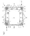
- the platform 2 is mounted by means of four bearing means L1, L2, L3, L4 arranged thereon on associated threaded spindles G1, G2, G3, G4, which are in accordance with FIG Fig. 2 different radial bearing clearance F1; F2 in the horizontal direction X; Y have.
- a plurality of adjustable side stops 23 and rear stops 24 are mounted, which extend in the stroke direction and act laterally on the stack of sheets. In Fig. 1 these stops are omitted because of the clearer presentation of the invention.
- the platform 2, together with the bearing means, can be moved axially along the spindles vertically in the direction Z, for which purpose all threaded spindles G1, G2, G3, G4 of the Spindle drive 1 synchronously by means of a single microprocessor-controlled drive unit 6 are rotatably driven in common.
- the drive unit 6 is controlled by a conventional, not shown control unit and sensor unit of the copying machine in its direction of rotation and rotation and has a drive motor 60 with drive pinion, as well as a driven via the drive pinion drive belt 61 in the form of a toothed belt.
- the toothed belt 61 is encircling all the belt wheels 62, which are arranged concentrically and rigidly connected to the threaded spindles G1, G2, G3, G4 in the region of the lower bearing plate 52.
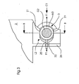
- a first bearing means L1 of the platform 2 is arranged substantially radially clearance on a first spindle G1, has a second bearing means L2, according to Fig. 1 to 4a , a radial bearing clearance F1 on both sides of a second spindle G2 in the direction Y, which is provided radially linearly extending to and away from the first spindle G1, and are, after Fig. 1 . 2 . 4b and 4c , the third and further bearing means L3, L4 with radial all-around bearing clearance F2 (in the direction X; Y) are arranged around the associated third and further spindles G3, G4.
- the bearing means L1, L2, L3, L4 of the platform 2 are arranged in the embodiment according to the invention as low-friction bearing means with radial clearance F1, F2 for equalizing the radial stroke of the rotating threaded spindles G1, G2, G3, G4, such that a relative, radial Movement of the rotating spindles G1, G2, G3, G4 to the platform 2 with low frictional force or low effort is possible.
- Fig. 1 The bearing means L1, L2, L3, L4 of the platform 2 are arranged in the embodiment according to the invention as low-friction bearing means with radial clearance F1, F2 for equalizing the radial stroke of the rotating threaded spindles G1, G2, G3, G4, such that a relative, radial Movement of the rotating spindles G1, G2, G3, G4 to the platform 2 with low frictional force or low effort is possible.
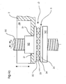
- the bearing means L1, L2, L3, L4 each have an annular ball bearing 3 arranged concentrically around the spindles G1, G2, G3, G4, by means of which the radial bearing clearance F1 and F2 between the platform 2 and the spindles for balancing the lead screw stroke is generated friction.
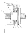
- the ball bearings 3 have, as in Fig. 3 . 4a-4b shown, in each case a first plane, for lifting movement aligned at right angles lower annular bearing shell 31 and a second plane, plane-parallel to the first aligned upper annular bearing shell 32, between which, held by an annular cage 33, 33.1, 33.2, balls 34 of the ball bearings freely rotatably mounted wherein the first bearing shell 31 of the ball bearings 3 is rigidly connected to the associated platform nut 2 with an associated spindle nut M1; M2; M3; M4 of the bearing means L1; L2; L3; L4 and the second bearing shell 32.
- the bearing shells 31, 32 have, in the radial direction, a planar support width for the balls 34, which is greater than the maximum radial bearing clearance F1, F2 predetermined by the maximum spindle stroke, and the ball cage 33 has an outer 33.1 and a ball around the balls 34 an inner ring member in concentric arrangement about the spindles G1; G2; G3; G4 and about the spindle nuts M1; M2; M3; M4, the inner ring member 33.2 having an inner diameter corresponding to an outer diameter of the spindle nut M1; M2; M3; M4 substantially corresponds.
- the bearing means L1, L2, L3, L4 each have an annular concentric ball bearing 4 arranged concentrically around a threaded spindle G1, G2, G3, G4 and having a first / lower concave, ball-guiding bearing shell 41 of the ball bearing 4, which is rigid with one M4; M4 of the bearing means L1; L2; L3; L4 is connected, and whose second / upper bearing shell 42 is rigidly connected to the platform 2 in a plane-parallel position relative to the first bearing shell 41 and has a planar support side for having freely rotating balls 44 of the ball bearing 4.
- the spindle nuts M1, M2, M3, M4 arranged on the threaded spindles G1, G2, G3, G4 and movable by rotation of the spindles have, as in FIG Fig. 4a-4b shown, an axially to the axis of rotation of the spindles extending cylindrical shape or a cylindrical shank, wherein at the lower end of each spindle nut, a radially projecting cylindrical flange is mounted concentrically.
- the lower / first annular bearing shell 31 is arranged on this flange of the spindle nut resting, centered by a smaller diameter exhibiting concentric ring member of the flange and rigidly connected to the flange (eg by press fit from the inner periphery of the bearing shell 31 on the outer circumference of the ring member).
- Each upper / second annular bearing shell 32 of the ball bearings 33 is rigid at an underside of the platform 2, or their bearing points L1; L2; L3; L4, in the region of a passage opening for the associated spindle G1; G2; G3; G4 in an annular recess
- the upper bearing shell 32 of the ball bearing 3 and the spindle passage opening on the platform 2 in this case have an inner diameter of their passage openings whose radius by the amount of the required predetermined radial bearing clearance F1; F2 of the individual bearing points of the bearing means L1; L2; L3; L4 is greater than a radius of the outer diameter of the upper cylindrical shaft of the spindle nut M1; M2; M3; M4 projecting upwards through the passage openings.
- the outer diameter of the upper cylindrical shaft of the spindle nut also serves to center and guide the inner ring member 33.2 of the annular ball cage 33rd
- a limitation of the radial bearing clearance F1, F2 between the bearing means 3, L2, L3, L4 of the bearing points or the platform 2 and the spindles G2, G3, G4 or the spindle nuts M1, M2, M3, M4 is by means of the platform 2 arranged and on the spindle nuts radially outwardly acting limiting means 21, 22 of the platform 2 effected, that is, the inner edge of the spindle passage openings at the bearing points L2, L3, L4 is formed as a limiting means 21, 22 for the radial bearing clearance F1, F2.
- the spindle nuts are by means of holding means, for example in the form of retaining bolts 25 with the bearing points L1; L2; L3; L4 or loosely coupled to the platform 2 (see Fig. 3 ).
- the retaining bolt 25 is rigidly connected to the cylindrical shank of the spindle nut M2, M3, M4 and protrudes at its opposite end, freely movable in the axial direction (according to the bearing clearance F1) through a guide bore on a web 26 of the platform or inside Platform storage L2; L3; L4.
- the guide bore is chosen so large in its diameter that the radial bearing clearance F2 is ensured by the circular horizontal movement of the retaining bolt 25.
- An exception here is the bearing point L1 with spindle nut M1, since this spindle nut can be rigidly and directly connected to the platform 2 because of the predetermined play-free bearing L1 with its cylindrical shank.
- limiting the radial bearing clearance F2 between the bearing means 3; M1, M2, M3, M4 of the bearing points L1, L2, L3, L4 and the spindles G1, G2, G3, G4, and for preventing a horizontal radial movement of the platform 2 in the X, Y direction during its lifting movement are stationary, device-side limiting means 50 which engage at right angles to the lifting movement on all four sides of the platform 2 or on the bottom plate 20 for the sheet stack stops 23, 24.
- the limiting means 50 are designed, for example, in the form of ribs or webs as part of the spindle drive housing 5 and extend along the lifting movement over the entire lifting height of the platform 2.
- the spindles G1, G2, G3, G4 have a combination of threaded spindles and smooth cylinder shafts or cylinder columns, wherein the cylinder shafts serve to guide and as anti-twist and Verkipptik for the platform 2.
- the spindle nuts are replaced by guide sleeves.
- only three rather than four spindles are provided in a polygon or triangle arrangement.
Landscapes
- Life Sciences & Earth Sciences (AREA)
- Engineering & Computer Science (AREA)
- Geology (AREA)
- Mechanical Engineering (AREA)
- Structural Engineering (AREA)
- Rolling Contact Bearings (AREA)
- Transmission Devices (AREA)
- Spinning Or Twisting Of Yarns (AREA)
- Turning (AREA)
- Machine Tool Units (AREA)
- Portable Nailing Machines And Staplers (AREA)
Claims (11)
- Dispositif de levage comprenant une plate-forme, plusieurs broches à vis (G1 ; G2 ; G3 ; G4) à axes parallèles, plusieurs paliers (L1 ; L2 ;L3 ; L4) dans une disposition polygonale permettant de porter la plate-forme par les broches à vis, caractérisé par des paliers présentant un certain jeu de palier (F1, F2) dans le sens radial pour compenser le battement des broches à vis dans le sens radial lors de leur rotation, un premier palier (L1) de la plate-forme (2) étant disposé sensiblement dans le sens radial et sans jeu sur une première broche à vis (G1), un deuxième palier (L2) présentant un jeu de palier radial (F1) de part et d'autre d'une deuxième broche à vis (G2), ce jeu radial étant orienté dans le sens linéaire en partant et en se rapprochant de la première broche à vis (G1) ; le troisième et d'autres paliers (L3, L4) étant disposés avec un jeu de palier radial (F2) orienté dans le sens circonférentiel autour des troisième et autres broches à vis (G3. G4) associées.
- Dispositif de levage selon la revendication 1, caractérise en ce que les paliers (L1 ; L2 ;13 ; L4) comprennent chacun un roulement à billes (3) annulaire dispose de manière concentrique autour des broches à vis (G1 ; G2 ; G3 ; G4), ce roulement à billes pouvant produire un jeu de palier radial (F1 ; F2) à faible frottement entre la plate-tonne (2) et les broches à vis pour compenser le battement des broches à vis.
- Dispositif de levage selon la revendication 1, caractérisé en ce qu'une délimitation du jeu de palier radial (F1 ; F2) entre les paliers (L2 ; L3 ;L4) et les broches à vis (G2 ; G3 ; G4) peut être réalisée par des moyens de délimitation (21 ; 22) disposés sur la plate-forme (2) et s'appuyant sur les broches à vis dans le sens radial.
- Dispositif de levage selon la revendication 1, caractérisé en ce que des moyens de délimitation (50) sont fixés sur l'équipement pour limiter le jeu de palier radial (F2) entre les paliers (L1 ; L2 ; L3 ; L4) et les broches à vis (G1 ; G2 ; G3 ; G4) et pour éviter tout mouvement radial de la plate-forme (2), ces moyens de délimitation s'appuyant sur les quatre côtés de la plate-forme (2) dans le sens perpendiculaire par rapport au mouvement de levage.
- Dispositif de levage selon la revendication 1, caractérisé en ce que les paliers (L1 ; L2 ; L3 ; L4) comprennent chacun un roulement à billes (3) annulaire disposé de manière concentrique autour des broches à vis (G1 ;G2 ; G3 ; G4), ce roulement à billes pouvant produire un jeu de palier radial (F1 ; F2) à faible frottement entre la plate-forme (2) et les broches à vis pour compenser le battement des broches à vis.
- Dispositif de levage selon la revendication 5, caractérisé en ce que les roulements à billes (3) comprennent chacun un premier coussinet (31) à surface plane orienté perpendiculairement au sens de levage et un deuxième coussinet (32) à surface plane disposé parallèlement au premier coussinet de façon à permettre aux billes (34) retenues par une cage annulaire (33 : 33.1 ; 33.2) de tourner librement dans le roulement à billes, le premier coussinet (31) des roulements à billes (3) étant relié de manière solidaire à un écrou de broche (M1 ; M2 ; M3 ; M4) associé aux paliers (L1 ; L2 ; L3 ; L4) et le second coussinet (32) étant relié de manière solidaire à la plate-forme (2).
- Dispositif de levage selon la revendication 6, caractérisé en ce que les coussinets (31 ; 32) présentent une surface d'appui plane pour les billes (34) dans le sens radial dont la largeur est supérieure au jeu de palier (F1 ; F2) maximal dans le sens radial défini au préalable par le battement maximal des broches à vis et en ce que la cage à billes (33 ; 33.1 ; 33.2) autour des billes (34) comprend un élément annulaire extérieur (33.1) et un élément annulaire intérieur (33.2) dans une disposition concentrique autour des broches à vis (G1 ; G2 ; G3 ; G4), l'élément annulaire intérieur (33.2) ayant un diamètre intérieur sensiblement identique au diamètre extérieur de l'écrou de broche (M1 ; M2 ; M3 ; M4).
- Dispositif de levage selon la revendication 5, caractérisé en ce que les paliers (L1 ; L2 ; L3 ; L4) comprennent chacun un roulement à billes (4) annulaire dans une disposition concentrique autour d'une broche à vis (G1 ; G2 ; G3 ; G4), un premier coussinet (41) à surface concave servant de guide pour les billes du roulement à billes étant relié de manière solidaire à un écrou de broche (M1 ; M2 ; M3 ; M4) des paliers (L1 ; L2 ; L3 ; L4) et dont le second coussinet (42), disposé parallèlement au premier coussinet (41), est relié de manière solidaire à la plate-forme (2) mais présente une face d'appui plane pour les billes (44) du roulement à billes (4).
- Dispositif de levage selon les revendications 1 à 7, caractérisé en ce que toutes les broches à vis (G1 ; G2 ; G3 ; G4) du système à broches (1) peuvent être entraînées de manière synchronisée par une seule unité d'entraînement (6) gérée par un micro-processeur et en ce que le système à broches (1), avec sa plate-forme (2), produit un mouvement de levage orienté dans le sens vertical.
- Dispositif de levage selon les revendications 1 à 9, caractérisé en ce qu'il est réalisé sous la forme d'un appareil de traitement de feuilles de papier, notamment d'un copieur.
- Dispositif de levage selon les revendications 1 9, caractérise en ce que les broches à vis (G1 ; G2 ; G3 ; G4) présentent une combinaison de tiges filetées et de tiges cylindriques, ces dernières ayant pour fonction de guider la plate-forme (2) et d'assurer une protection contre la torsion et le basculement.
Applications Claiming Priority (2)
| Application Number | Priority Date | Filing Date | Title |
|---|---|---|---|
| DE2000108908 DE10008908A1 (de) | 2000-02-25 | 2000-02-25 | Vorrichtung zum Ausgleichen eines radialen Gewindespindelschlags eines Spindeltriebs |
| DE10008908 | 2000-02-25 |
Publications (3)
| Publication Number | Publication Date |
|---|---|
| EP1132329A2 EP1132329A2 (fr) | 2001-09-12 |
| EP1132329A3 EP1132329A3 (fr) | 2004-03-17 |
| EP1132329B1 true EP1132329B1 (fr) | 2009-06-24 |
Family
ID=7632406
Family Applications (1)
| Application Number | Title | Priority Date | Filing Date |
|---|---|---|---|
| EP01101674A Expired - Lifetime EP1132329B1 (fr) | 2000-02-25 | 2001-01-30 | Dispositif pour compenser un mouvement radial de la vis dans une transmission vis - écrou |
Country Status (4)
| Country | Link |
|---|---|
| EP (1) | EP1132329B1 (fr) |
| JP (1) | JP2001270692A (fr) |
| AT (1) | ATE434584T1 (fr) |
| DE (2) | DE10008908A1 (fr) |
Families Citing this family (5)
| Publication number | Priority date | Publication date | Assignee | Title |
|---|---|---|---|---|
| JP4012946B2 (ja) * | 2003-08-21 | 2007-11-28 | ▲高▼田 嘉宏 | 攪拌機用昇降装置 |
| CN104444943A (zh) * | 2014-11-26 | 2015-03-25 | 哈尔滨工程大学 | 用于离心风机的可移动升降台 |
| CN112194045A (zh) * | 2020-10-15 | 2021-01-08 | 刘玉 | 一种太阳能电板安装运输用升降机构 |
| CN114890336B (zh) * | 2022-04-15 | 2023-07-04 | 中交第四公路工程局有限公司 | 一种钢结构部件运转装置及运转方法 |
| DE102025110539B3 (de) * | 2025-01-14 | 2026-01-22 | Vero Veria Corporation | Hebemechanismus und hebevorrichtung eines erhöhten bodens |
Family Cites Families (11)
| Publication number | Priority date | Publication date | Assignee | Title |
|---|---|---|---|---|
| GB621020A (en) * | 1944-03-30 | 1949-04-04 | Julio Villars | Improvements in or relating to apparatus for lifting vehicles |
| FR53985E (fr) * | 1945-02-26 | 1947-01-14 | Appareil de levage | |
| DE2417645A1 (de) * | 1974-04-10 | 1975-10-30 | Rietbergwerke Kg | Foerdervorrichtung, insbesondere zum heben von lasten |
| DD141129A1 (de) * | 1979-02-01 | 1980-04-16 | Rainer Hradetzky | Verfahren und einrichtung zur steuerung des zumessens von mischungsbestandteilen |
| DE2906172C2 (de) * | 1979-02-17 | 1984-04-12 | Gebr. Hofmann Gmbh & Co Kg Maschinenfabrik, 6100 Darmstadt | Sicherheitseinrichtung für eine spindelbetriebene Hebeeinrichtung, insbesondere Zwei-Säulen-Kraftfahrzeug-Hebebühne |
| US4326643A (en) | 1979-09-04 | 1982-04-27 | Standard Change-Makers, Inc. | Magnetic ticket dispenser |
| DE3514804A1 (de) | 1985-04-24 | 1986-11-06 | Hartmut Dipl.-Ing. 8013 Haar Kosche | Hubvorrichtung |
| DD238601A1 (de) * | 1985-06-24 | 1986-08-27 | Fortschritt Veb K | Spindelmutter |
| CH674977A5 (en) * | 1987-10-14 | 1990-08-15 | Kurt Ruenzi | Sheet separating paper stacker for photocopier - has horizontal table movable vertically in housing supported by four clamps secured at vertical section of wire rope |
| DE4343685C2 (de) * | 1993-12-21 | 1996-05-23 | Nussbaum Otto Gmbh Co Kg | Absturzsicherung und Haltevorrichtung für eine Hubvorrichtung |
| DE19960654A1 (de) * | 1999-12-15 | 2001-06-28 | Hiller & Lutz Gmbh & Co | Hebevorrichtung |
-
2000
- 2000-02-25 DE DE2000108908 patent/DE10008908A1/de not_active Withdrawn
-
2001
- 2001-01-30 EP EP01101674A patent/EP1132329B1/fr not_active Expired - Lifetime
- 2001-01-30 AT AT01101674T patent/ATE434584T1/de not_active IP Right Cessation
- 2001-01-30 DE DE50114943T patent/DE50114943D1/de not_active Expired - Lifetime
- 2001-02-26 JP JP2001050994A patent/JP2001270692A/ja active Pending
Also Published As
| Publication number | Publication date |
|---|---|
| DE10008908A1 (de) | 2001-08-30 |
| EP1132329A2 (fr) | 2001-09-12 |
| JP2001270692A (ja) | 2001-10-02 |
| ATE434584T1 (de) | 2009-07-15 |
| EP1132329A3 (fr) | 2004-03-17 |
| DE50114943D1 (de) | 2009-08-06 |
Similar Documents
| Publication | Publication Date | Title |
|---|---|---|
| EP1441026B1 (fr) | Système de stockage automatique et armoire de climatisation avec un tel système de stockage automatique | |
| DE60205040T2 (de) | Durch einen beweglichen arm aktivierter werkzeugwechsler für ein werkzeugmaschinensystem mit spezieller werkzeugklemme | |
| EP0376035B1 (fr) | Fichier à manèges multiples | |
| EP3339223B1 (fr) | Poste de travail réglable ergonomique avec des billes | |
| DE68910810T2 (de) | Anlage mit angetriebenen kugeln und deck. | |
| DE60112344T2 (de) | Magazin mit automatischer Ausgabevorrichtung für vorgewählte lose Gegenstände, insbesondere für Gewichte zum Auswuchten von Fahrzeugrädern | |
| DE2443373A1 (de) | Lochstanze oder knabberpresse mit werkzeugwechsler | |
| DE3784588T2 (de) | Dokumentenspender. | |
| EP0288700B1 (fr) | Dispositif pour transporter et calibrer des feuilles pour des machines à traitement de feuilles | |
| EP1132329A2 (fr) | Dispositif pour compenser un mouvement radial de la vis dans une transmission vis - écrou | |
| DE60302884T2 (de) | Bodeneinheit für streckfolienwickelmaschine | |
| DE102011004537A1 (de) | Bearbeitungsvorrichtung mit Tastrolle | |
| EP2033735B1 (fr) | Dispositif de changement d'outil compact | |
| EP1502881B1 (fr) | L'aide de mise en position et procédure de soutien de l'alignement des appareils lourds | |
| DE69211262T2 (de) | Blattstapeleinrichtung mit zwei Ecken | |
| EP2181954A2 (fr) | Dispositif de réglage de palettes | |
| DE3532470A1 (de) | Rueckholhaspel fuer einen fahrzeug-sicherheitsgurt | |
| DE10201008A1 (de) | Hubsystem für eine Plattform und Wägesystem mit einem solchen | |
| US20020069714A1 (en) | Device for balancing of a radial threaded spindle eccentricity of a spindle drive | |
| DE102022119374B3 (de) | Waage mit Magazin und Lastwechseleinrichtung | |
| DE4109877C2 (fr) | ||
| EP0240812A2 (fr) | Système d'emmagasinage | |
| EP0827925B1 (fr) | Margeur de feuilles pour machines à imprimer | |
| EP0847818B1 (fr) | Presse de transfert | |
| DE3416171A1 (de) | Palettentraeger fuer werkzeugmaschine |
Legal Events
| Date | Code | Title | Description |
|---|---|---|---|
| PUAI | Public reference made under article 153(3) epc to a published international application that has entered the european phase |
Free format text: ORIGINAL CODE: 0009012 |
|
| AK | Designated contracting states |
Kind code of ref document: A2 Designated state(s): AT BE CH CY DE DK ES FI FR GB GR IE IT LI LU MC NL PT SE TR |
|
| AX | Request for extension of the european patent |
Free format text: AL;LT;LV;MK;RO;SI |
|
| PUAL | Search report despatched |
Free format text: ORIGINAL CODE: 0009013 |
|
| AK | Designated contracting states |
Kind code of ref document: A3 Designated state(s): AT BE CH CY DE DK ES FI FR GB GR IE IT LI LU MC NL PT SE TR |
|
| AX | Request for extension of the european patent |
Extension state: AL LT LV MK RO SI |
|
| RIC1 | Information provided on ipc code assigned before grant |
Ipc: 7B 65H 1/14 B Ipc: 7B 66F 7/14 A |
|
| RAP1 | Party data changed (applicant data changed or rights of an application transferred) |
Owner name: EASTMAN KODAK COMPANY |
|
| AKX | Designation fees paid | ||
| REG | Reference to a national code |
Ref country code: DE Ref legal event code: 8566 |
|
| RBV | Designated contracting states (corrected) |
Designated state(s): AT BE CH CY DE DK ES FI FR GB GR IE IT LI LU MC NL PT SE TR |
|
| 17P | Request for examination filed |
Effective date: 20050211 |
|
| 17Q | First examination report despatched |
Effective date: 20081124 |
|
| GRAP | Despatch of communication of intention to grant a patent |
Free format text: ORIGINAL CODE: EPIDOSNIGR1 |
|
| GRAS | Grant fee paid |
Free format text: ORIGINAL CODE: EPIDOSNIGR3 |
|
| GRAA | (expected) grant |
Free format text: ORIGINAL CODE: 0009210 |
|
| AK | Designated contracting states |
Kind code of ref document: B1 Designated state(s): AT BE CH CY DE DK ES FI FR GB GR IE IT LI LU MC NL PT SE TR |
|
| REG | Reference to a national code |
Ref country code: GB Ref legal event code: FG4D Free format text: NOT ENGLISH |
|
| REG | Reference to a national code |
Ref country code: CH Ref legal event code: EP |
|
| REG | Reference to a national code |
Ref country code: IE Ref legal event code: FG4D Free format text: LANGUAGE OF EP DOCUMENT: GERMAN |
|
| REF | Corresponds to: |
Ref document number: 50114943 Country of ref document: DE Date of ref document: 20090806 Kind code of ref document: P |
|
| PG25 | Lapsed in a contracting state [announced via postgrant information from national office to epo] |
Ref country code: FI Free format text: LAPSE BECAUSE OF FAILURE TO SUBMIT A TRANSLATION OF THE DESCRIPTION OR TO PAY THE FEE WITHIN THE PRESCRIBED TIME-LIMIT Effective date: 20090624 |
|
| PG25 | Lapsed in a contracting state [announced via postgrant information from national office to epo] |
Ref country code: SE Free format text: LAPSE BECAUSE OF FAILURE TO SUBMIT A TRANSLATION OF THE DESCRIPTION OR TO PAY THE FEE WITHIN THE PRESCRIBED TIME-LIMIT Effective date: 20090924 |
|
| NLV1 | Nl: lapsed or annulled due to failure to fulfill the requirements of art. 29p and 29m of the patents act | ||
| PG25 | Lapsed in a contracting state [announced via postgrant information from national office to epo] |
Ref country code: ES Free format text: LAPSE BECAUSE OF FAILURE TO SUBMIT A TRANSLATION OF THE DESCRIPTION OR TO PAY THE FEE WITHIN THE PRESCRIBED TIME-LIMIT Effective date: 20091005 |
|
| REG | Reference to a national code |
Ref country code: IE Ref legal event code: FD4D |
|
| PG25 | Lapsed in a contracting state [announced via postgrant information from national office to epo] |
Ref country code: NL Free format text: LAPSE BECAUSE OF FAILURE TO SUBMIT A TRANSLATION OF THE DESCRIPTION OR TO PAY THE FEE WITHIN THE PRESCRIBED TIME-LIMIT Effective date: 20090624 |
|
| PG25 | Lapsed in a contracting state [announced via postgrant information from national office to epo] |
Ref country code: PT Free format text: LAPSE BECAUSE OF FAILURE TO SUBMIT A TRANSLATION OF THE DESCRIPTION OR TO PAY THE FEE WITHIN THE PRESCRIBED TIME-LIMIT Effective date: 20091024 |
|
| PG25 | Lapsed in a contracting state [announced via postgrant information from national office to epo] |
Ref country code: IE Free format text: LAPSE BECAUSE OF FAILURE TO SUBMIT A TRANSLATION OF THE DESCRIPTION OR TO PAY THE FEE WITHIN THE PRESCRIBED TIME-LIMIT Effective date: 20090624 Ref country code: DK Free format text: LAPSE BECAUSE OF FAILURE TO SUBMIT A TRANSLATION OF THE DESCRIPTION OR TO PAY THE FEE WITHIN THE PRESCRIBED TIME-LIMIT Effective date: 20090624 |
|
| PLBE | No opposition filed within time limit |
Free format text: ORIGINAL CODE: 0009261 |
|
| STAA | Information on the status of an ep patent application or granted ep patent |
Free format text: STATUS: NO OPPOSITION FILED WITHIN TIME LIMIT |
|
| 26N | No opposition filed |
Effective date: 20100325 |
|
| BERE | Be: lapsed |
Owner name: EASTMAN KODAK CY Effective date: 20100131 |
|
| PG25 | Lapsed in a contracting state [announced via postgrant information from national office to epo] |
Ref country code: MC Free format text: LAPSE BECAUSE OF NON-PAYMENT OF DUE FEES Effective date: 20100131 |
|
| REG | Reference to a national code |
Ref country code: CH Ref legal event code: PL |
|
| PG25 | Lapsed in a contracting state [announced via postgrant information from national office to epo] |
Ref country code: GR Free format text: LAPSE BECAUSE OF FAILURE TO SUBMIT A TRANSLATION OF THE DESCRIPTION OR TO PAY THE FEE WITHIN THE PRESCRIBED TIME-LIMIT Effective date: 20090925 Ref country code: LI Free format text: LAPSE BECAUSE OF NON-PAYMENT OF DUE FEES Effective date: 20100131 Ref country code: CH Free format text: LAPSE BECAUSE OF NON-PAYMENT OF DUE FEES Effective date: 20100131 |
|
| PG25 | Lapsed in a contracting state [announced via postgrant information from national office to epo] |
Ref country code: BE Free format text: LAPSE BECAUSE OF NON-PAYMENT OF DUE FEES Effective date: 20100131 |
|
| PG25 | Lapsed in a contracting state [announced via postgrant information from national office to epo] |
Ref country code: IT Free format text: LAPSE BECAUSE OF FAILURE TO SUBMIT A TRANSLATION OF THE DESCRIPTION OR TO PAY THE FEE WITHIN THE PRESCRIBED TIME-LIMIT Effective date: 20090624 |
|
| PGFP | Annual fee paid to national office [announced via postgrant information from national office to epo] |
Ref country code: GB Payment date: 20101215 Year of fee payment: 11 |
|
| PG25 | Lapsed in a contracting state [announced via postgrant information from national office to epo] |
Ref country code: AT Free format text: LAPSE BECAUSE OF NON-PAYMENT OF DUE FEES Effective date: 20100130 |
|
| PGFP | Annual fee paid to national office [announced via postgrant information from national office to epo] |
Ref country code: FR Payment date: 20120111 Year of fee payment: 12 |
|
| PG25 | Lapsed in a contracting state [announced via postgrant information from national office to epo] |
Ref country code: CY Free format text: LAPSE BECAUSE OF FAILURE TO SUBMIT A TRANSLATION OF THE DESCRIPTION OR TO PAY THE FEE WITHIN THE PRESCRIBED TIME-LIMIT Effective date: 20090624 |
|
| PG25 | Lapsed in a contracting state [announced via postgrant information from national office to epo] |
Ref country code: LU Free format text: LAPSE BECAUSE OF NON-PAYMENT OF DUE FEES Effective date: 20100130 |
|
| PG25 | Lapsed in a contracting state [announced via postgrant information from national office to epo] |
Ref country code: TR Free format text: LAPSE BECAUSE OF FAILURE TO SUBMIT A TRANSLATION OF THE DESCRIPTION OR TO PAY THE FEE WITHIN THE PRESCRIBED TIME-LIMIT Effective date: 20090624 |
|
| PGFP | Annual fee paid to national office [announced via postgrant information from national office to epo] |
Ref country code: DE Payment date: 20130131 Year of fee payment: 13 |
|
| GBPC | Gb: european patent ceased through non-payment of renewal fee |
Effective date: 20130130 |
|
| REG | Reference to a national code |
Ref country code: FR Ref legal event code: ST Effective date: 20130930 |
|
| PG25 | Lapsed in a contracting state [announced via postgrant information from national office to epo] |
Ref country code: FR Free format text: LAPSE BECAUSE OF NON-PAYMENT OF DUE FEES Effective date: 20130131 Ref country code: GB Free format text: LAPSE BECAUSE OF NON-PAYMENT OF DUE FEES Effective date: 20130130 |
|
| REG | Reference to a national code |
Ref country code: DE Ref legal event code: R119 Ref document number: 50114943 Country of ref document: DE |
|
| PG25 | Lapsed in a contracting state [announced via postgrant information from national office to epo] |
Ref country code: DE Free format text: LAPSE BECAUSE OF NON-PAYMENT OF DUE FEES Effective date: 20140801 |
|
| REG | Reference to a national code |
Ref country code: DE Ref legal event code: R119 Ref document number: 50114943 Country of ref document: DE Effective date: 20140801 |