EP0288882A2 - Dispositif de fixation pour dispositif antidérapage de pneumatique - Google Patents
Dispositif de fixation pour dispositif antidérapage de pneumatique Download PDFInfo
- Publication number
- EP0288882A2 EP0288882A2 EP88106252A EP88106252A EP0288882A2 EP 0288882 A2 EP0288882 A2 EP 0288882A2 EP 88106252 A EP88106252 A EP 88106252A EP 88106252 A EP88106252 A EP 88106252A EP 0288882 A2 EP0288882 A2 EP 0288882A2
- Authority
- EP
- European Patent Office
- Prior art keywords
- fastener
- tyre
- preventing device
- slippage preventing
- connecting portion
- Prior art date
- Legal status (The legal status is an assumption and is not a legal conclusion. Google has not performed a legal analysis and makes no representation as to the accuracy of the status listed.)
- Ceased
Links
- 239000013013 elastic material Substances 0.000 claims description 5
- 239000012779 reinforcing material Substances 0.000 claims description 2
- 230000008878 coupling Effects 0.000 description 8
- 238000010168 coupling process Methods 0.000 description 8
- 238000005859 coupling reaction Methods 0.000 description 8
- 229920001971 elastomer Polymers 0.000 description 6
- 229920006311 Urethane elastomer Polymers 0.000 description 2
- 229910003460 diamond Inorganic materials 0.000 description 2
- 239000010432 diamond Substances 0.000 description 2
- 230000003014 reinforcing effect Effects 0.000 description 2
- 229920005989 resin Polymers 0.000 description 2
- 239000011347 resin Substances 0.000 description 2
- 238000005452 bending Methods 0.000 description 1
- 230000007423 decrease Effects 0.000 description 1
- 239000000835 fiber Substances 0.000 description 1
- 239000000463 material Substances 0.000 description 1
- 239000002184 metal Substances 0.000 description 1
- 238000000034 method Methods 0.000 description 1
- 229920003002 synthetic resin Polymers 0.000 description 1
- 239000000057 synthetic resin Substances 0.000 description 1
Images



Classifications
-
- B—PERFORMING OPERATIONS; TRANSPORTING
- B60—VEHICLES IN GENERAL
- B60C—VEHICLE TYRES; TYRE INFLATION; TYRE CHANGING; CONNECTING VALVES TO INFLATABLE ELASTIC BODIES IN GENERAL; DEVICES OR ARRANGEMENTS RELATED TO TYRES
- B60C27/00—Non-skid devices temporarily attachable to resilient tyres or resiliently-tyred wheels
- B60C27/06—Non-skid devices temporarily attachable to resilient tyres or resiliently-tyred wheels extending over the complete circumference of the tread, e.g. made of chains or cables
- B60C27/16—Non-skid devices temporarily attachable to resilient tyres or resiliently-tyred wheels extending over the complete circumference of the tread, e.g. made of chains or cables formed of close material, e.g. leather or synthetic mats
-
- B—PERFORMING OPERATIONS; TRANSPORTING
- B60—VEHICLES IN GENERAL
- B60C—VEHICLE TYRES; TYRE INFLATION; TYRE CHANGING; CONNECTING VALVES TO INFLATABLE ELASTIC BODIES IN GENERAL; DEVICES OR ARRANGEMENTS RELATED TO TYRES
- B60C27/00—Non-skid devices temporarily attachable to resilient tyres or resiliently-tyred wheels
- B60C27/06—Non-skid devices temporarily attachable to resilient tyres or resiliently-tyred wheels extending over the complete circumference of the tread, e.g. made of chains or cables
- B60C27/10—Non-skid devices temporarily attachable to resilient tyres or resiliently-tyred wheels extending over the complete circumference of the tread, e.g. made of chains or cables having tensioning means
Definitions
- the present invention relates to a fastener for a tyre slippage preventing device which may in particular be suitably used with a flexible tyre slippage preventing device made of rubber or a synthetic resin.
- Ladder- or net-shaped tyre slippage preventing devices made of rubber or urethane elastomer have been known.
- Fig. 7 shows one example of a tyre slippage preventing device of the above-described type.
- a plurality of hooks 14 and 16 are respectively connected to the two lateral edges of a body 12 of the tyre slippage preventing device in such a manner that they are disposed in a line parallel to the edges of the body 12.
- An inner fastener 18 which may be a rope or a wire rope made of a resin having a relatively small modulus of stretch is engaged with the hooks 14 connected to one edge.
- a joint hook 20 which is engaged with the body 12 is connected to one end of the inner fastener 18, and a joint hook 22 which connects the two ends of the inner fastener 18 is connected to the other end.
- the body 12 is placed around a tyre in such a manner that the side of the body to which the hooks 14 are connected is disposed at the inner side of the tyre.
- the inner fastener 18 is formed into a ring-like shape by hooking the joint hook 22 to a loop portion 18A attached to the joint hook 20 and by hooking the joint hook 20 to an inner joint hole 24 formed in the body 12.
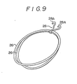
- a joint hook 28 which is bifurcated to have two hooks 28A is connected to the outer fasteners 29, as shown in Fig. 9.
- the hooks 28A of the joint hook 28 are received by two outer joint holes 30 formed in the body 12.
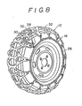
- the body 12 is formed to assume a cylindrical shape and is mounted on a tyre 32 by means of the inner fastener 18 and the outer fasteners 26.
- outer fasteners 26 cannot serve their function as fasteners if they should happen to be cut at one location.
- Japanese Utility Model Laid-Open No. 110387/1983 proposes a fastener of the type shown in Fig. 10.
- a body 34 of the fastener is made of an elastic material and has band portions 36.
- a hook 38 which is connected to the distal end of each of the band portions 36 is engaged with a tyre chain 40 such as that shown in Fig. 11.
- an object of the present invention is to provide a fastener for a tyre slippage preventing device which is capable of preventing the body of the tyre slippage preventing device from becoming disengaged from the periphery of the tyre and being dragged in toward the axle, and which has a simple structure which enables the fastener to be coupled to the tyre slippage preventing device body.
- a fastener for a tyre slippage preventing device which is characterized in that a ring-shaped connecting portion and arm portions extending radialy outward from the connecting portion are formed from an elastic material as one unit, and that the distal end of each of the arm portions is provided with an engaging hole with which a fitment connected to the body of the tyre slippage preventing device may be engaged.
- the engaging holes formed in the fastener are directly engaged with the hooks connected to the body of the tyre slippage preventing device.
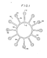
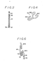
- Figs. 1 and 2 show an embodiment of a fastener for a tyre slippage preventing device according to the present invention.
- a fastener 50 is made of an elastic material such as rubber or urethane elastomer as one unit. It has a ring-shaped connecting portion 52, and twelve arm portions 54 which extend radialy from the connecting portion 52 at equal intervals and have the same shape. The distal end of each of the arms 54 is formed into a loop, and the central through-hole of the loop forms an engaging hole 56.
- a reinforcing material 58 such as cord or canvas may be sealed within the elastic material of the fastener 50 around the engaging holes 56 and at the connecting portion 52, as shown in Fig. 2.
- the radius of the connecting portion 52 is between 30 and 70 % of the distance between the center of the connecting portion 52 and the center of the engaging hole 56. More preferably, it is between 40 and 60 %, and most preferably, it is in the vicinity of 50 %.
- Fig. 3 shows a body 60 of the tyre slippage preventing device which is combined with the fastener 50 of this embodiment.
- the body 60 is made of a net-shaped rubber with a reinforcing cord made of an organic fiber or a metal sealed therein. It is made up of outer frame portions 60A which are each substantially formed in the shape of a diamond, with the exception of the two longitudinal end portions, each of the outer frame portions 60A being formed with four small frame portions each of which are substantially formed in the shape of a diamond, and which have parts common to each other.
- the outer frame portions 60A are connected in the longitudinal direction of the body through small frame portions 60B that also extend in the longitudinal direction of the body.
- Each of the two end portions of the body forms an outer frame portion 60C which consists of one small, substantially diamond-shaped frame portion and two small, substantially triangular frame portions, parts of which are common to each other.
- the outer frame portions 60C are each connected to the outer frame portion 60A through the small frame portions 60Bs.
- one end of a connecting fitment 62 is caulked to each of the outer frame portions 60A and one of the outer frame portions 60C.
- the other end of the connecting fitment 62 is caulked to an inner fastener 64 which is a rope or a wire rope made of a resin having a relatively small modulus of stretch.
- One end of the inner fastener 64 forms a loop portion 64A, and the other end of the inner fastener is connected to a joint hook 65 which is caulked to the outer frame portion 60C.
- the joint hook 65 has a hook 65A which is to be received by the loop 64A.
- one end of a coupling fitment 66 is caulked to each of the outer frame portions 60A that are disposed in a line in the londitudinal direction of the body.
- the other end of the coupling fitment 66 is bent into a substantially U-shaped form toward the front of the body 60 (that is toward the front as viewed in Fig. 3) so as to form a hook 66A.
- a joint hook 68 is caulked to the one outer frame portion 60C.
- the joint hook 68 has a hook portion 68A at one end and is bifurcated to form two separate hook portions 68B and 68C at the other end, as shown in Fig. 4.
- One of these hook portions 68B is fixed to the outer frame portion 60C, as stated previously, and the other hook 68C is engaged with the other outer frame portion 60C.
- the body 60 is placed around the tyre 70 in such a manner that the side thereof on which the inner fastener 64 is provided is disposed on the inner side of the tyre 70.
- the inner fastener 64 is then formed into a loop by the engagement of the hook 65A of the joint hook 65 with the loop 64A.
- the hook 68C of the joint hook 68 is engaged with the outer frame portion 60C at the outer side of the tyre 70, and two auxiliary outer fasteners 72 which consist of elastic rings made of rubber are engaged with the hooks 66A of the coupling fitments 66 and the hook portion 68A of the joint hook 68.
- the holes 56 of the fastener 50 are then engaged with the hooks 66A and the hook portion 68A, so that the fastener 50 is positioned on the outer side of the tyre 70 in a state wherein the arm portions 54 of the fastener 50 are elastically deformed in the direction of tension.
- the body 60 is formed into a tube-like shape, and is mounted on the tyre 70 by being fastened by means of the inner fastener 64, the auxiliary outer fasteners 72 and the fastener 50.
- the fastener 50 Since the connecting portion 52 of the fastener 50 which fastens the body 60 to the tyre 70 has a diameter larger than that of the fastener disclosed in the specification of Japanese Utility Model Laid-Open No. 110387/1983, the fastener 50 is highly effective for fastening the body 60.
- each of the arm portions 54 becomes close to the body 60 and the length of each of the arm portions 54 becomes relatively short. This limits the area of movement of each of the engaging holes 56 in the circumferential direction of the tyre 70. This in turn limits the area of movement of each of the coupling fitments 66 and the joint hook 68, thereby reducing the deflection in the arrangement (an arranging pitch) of the coupling fitments 66 and joint hook 68.
- the connecting portion 52 If the diameter of the connecting portion 52 is excessively large, the same problem occurs as that with the outer fasteners 26 shown in Fig. 9. Therefore, it must be set to the above-described dimension. If the fastener 50 has a connecting portion 52 reinforced with the reinforcing cord 58, the connecting portion 52 hardly stretches and an increase in the diameter of the connecting portion 52 causes no problem. However, it reduces the length of the arm portions 54. This decreases the elongation of the arm portions 54 and requires a large amount of force to mount the fastener.
- the structure with which the fastener 50 is connected to the body 60 is made simple, and engagement of the hooks is eliminated.
- the arm portions 54 are extended radialy while they are coupled to each other at the central portion by means of the connecting portion 52, the body 60 is not shifted from the periphery of the tyre 70 so as to be wound around the axle.
- the fastener 50 can still serve its function as a fastener.
- Use of the auxiliary outer fasteners 72 together with the fastener 50 makes it possible for a vehicle to run safely for a while after the arm portions 54 or the auxiliary outer fastener 72 have been cut. Further, since the auxiliary outer fasteners 72 are engaged with the hooks 66A of the coupling fitments 66, use of the auxiliary outer fasteners 72 does not make the connecting structure between the fastener and the body 60 a complicated one.
- the fastener for the tyre slippage preventing device is capable of preventing the body of the tyre slippage preventing device from becoming disengaged from the periphery of the tyre and being dragged in toward the axle.
- the fastener of this invention can also be connected to the body with a simple structure.
Landscapes
- Engineering & Computer Science (AREA)
- Mechanical Engineering (AREA)
- Tires In General (AREA)
- Hooks, Suction Cups, And Attachment By Adhesive Means (AREA)
- Bolts, Nuts, And Washers (AREA)
Applications Claiming Priority (2)
| Application Number | Priority Date | Filing Date | Title |
|---|---|---|---|
| JP9698487 | 1987-04-20 | ||
| JP96984/87 | 1987-04-20 |
Publications (2)
| Publication Number | Publication Date |
|---|---|
| EP0288882A2 true EP0288882A2 (fr) | 1988-11-02 |
| EP0288882A3 EP0288882A3 (fr) | 1988-12-14 |
Family
ID=14179478
Family Applications (1)
| Application Number | Title | Priority Date | Filing Date |
|---|---|---|---|
| EP88106252A Ceased EP0288882A3 (fr) | 1987-04-20 | 1988-04-20 | Dispositif de fixation pour dispositif antidérapage de pneumatique |
Country Status (2)
| Country | Link |
|---|---|
| EP (1) | EP0288882A3 (fr) |
| JP (1) | JPS6428011A (fr) |
Cited By (2)
| Publication number | Priority date | Publication date | Assignee | Title |
|---|---|---|---|---|
| EP0351362A3 (en) * | 1988-07-13 | 1990-06-20 | Autotyp S.A. | Track for antislip device |
| EP0519213A1 (fr) * | 1991-05-20 | 1992-12-23 | " BARLOG" proizvodno in trgovsko podjetje, d.o.o. | Dispositif anti-dérapage pour pneumatiques d'automobile |
Family Cites Families (3)
| Publication number | Priority date | Publication date | Assignee | Title |
|---|---|---|---|---|
| DE1680436A1 (de) * | 1967-09-20 | 1971-08-26 | Anton Mangold | Schneekette fuer Personenkraftwagen |
| FR2192008A1 (fr) * | 1972-07-10 | 1974-02-08 | Rosso Louis | |
| JPS58110387U (ja) * | 1982-01-25 | 1983-07-27 | 日米ゴム株式会社 | タイヤチエ−ン締付用バンド |
-
1988
- 1988-04-14 JP JP9213788A patent/JPS6428011A/ja active Pending
- 1988-04-20 EP EP88106252A patent/EP0288882A3/fr not_active Ceased
Cited By (5)
| Publication number | Priority date | Publication date | Assignee | Title |
|---|---|---|---|---|
| EP0351362A3 (en) * | 1988-07-13 | 1990-06-20 | Autotyp S.A. | Track for antislip device |
| US5012848A (en) * | 1988-07-13 | 1991-05-07 | Autotyp S.A. | Antiskid device |
| EP0519213A1 (fr) * | 1991-05-20 | 1992-12-23 | " BARLOG" proizvodno in trgovsko podjetje, d.o.o. | Dispositif anti-dérapage pour pneumatiques d'automobile |
| US5267596A (en) * | 1991-05-20 | 1993-12-07 | "Barlog" Proizvodno In Trgovsko Podjetje, D.O.O. | Antiskid device for automobile tires |
| TR27800A (tr) * | 1991-05-20 | 1995-08-29 | Barlog | Otomobil dis lastikleri icin kaymaya karsi tertibat montaji. |
Also Published As
| Publication number | Publication date |
|---|---|
| JPS6428011A (en) | 1989-01-30 |
| EP0288882A3 (fr) | 1988-12-14 |
Similar Documents
| Publication | Publication Date | Title |
|---|---|---|
| US4782872A (en) | Cover for steering wheels | |
| JPH0270512A (ja) | 自動車車輪用滑り止め装置 | |
| US4836258A (en) | Attachment apparatus for a tire mat | |
| US4280545A (en) | Wire rope traction device for tires | |
| US5776271A (en) | Tire anti-skid apparatus | |
| US4456047A (en) | Connecting structure of traction device for vehicle wheels | |
| US4960159A (en) | Anti-skid device for tired vehicle wheels | |
| JP2845435B2 (ja) | タイヤ滑り止め装置 | |
| US4830078A (en) | Helical cable tire chain having multi-angular traction sleeves and rubber rings | |
| JPH057043Y2 (fr) | ||
| JPH0439768Y2 (fr) | ||
| JP2551152Y2 (ja) | タイヤ用滑り止めネット | |
| US4042000A (en) | Device for tire chains | |
| JPH10315724A (ja) | 自動車用タイヤ滑り止め装置 | |
| CA1122108A (fr) | Cable de traction pour montage sur pneumatiques | |
| JP2525992B2 (ja) | タイヤの滑止め装置 | |
| JP3652850B2 (ja) | タイヤ滑り止め具 | |
| JP2535332B2 (ja) | タイヤ滑り止め装置用取付具 | |
| JPH01309807A (ja) | タイヤ滑り止め装置用取付具 | |
| JP2524959B2 (ja) | タイヤ滑止め具 | |
| FI104801B (fi) | Puunsyöttölaitteen syöttöpyörän ketjun kiinnitysmekanismi | |
| JP2901751B2 (ja) | タイヤ滑り止め装置用取付バンド | |
| JP2575416Y2 (ja) | タイヤ滑り止め装置のジョイントフック付きテンションバンド | |
| JPH0421690Y2 (fr) | ||
| JPS6390409A (ja) | タイヤ滑り止め装置の取付方法 |
Legal Events
| Date | Code | Title | Description |
|---|---|---|---|
| PUAI | Public reference made under article 153(3) epc to a published international application that has entered the european phase |
Free format text: ORIGINAL CODE: 0009012 |
|
| PUAL | Search report despatched |
Free format text: ORIGINAL CODE: 0009013 |
|
| AK | Designated contracting states |
Kind code of ref document: A2 Designated state(s): CH DE FR LI |
|
| AK | Designated contracting states |
Kind code of ref document: A3 Designated state(s): CH DE FR LI |
|
| 17P | Request for examination filed |
Effective date: 19890222 |
|
| 17Q | First examination report despatched |
Effective date: 19900731 |
|
| STAA | Information on the status of an ep patent application or granted ep patent |
Free format text: STATUS: THE APPLICATION HAS BEEN REFUSED |
|
| 18R | Application refused |
Effective date: 19910420 |