EP0288886B1 - Agencement d'essuie-glace - Google Patents
Agencement d'essuie-glace Download PDFInfo
- Publication number
- EP0288886B1 EP0288886B1 EP88106284A EP88106284A EP0288886B1 EP 0288886 B1 EP0288886 B1 EP 0288886B1 EP 88106284 A EP88106284 A EP 88106284A EP 88106284 A EP88106284 A EP 88106284A EP 0288886 B1 EP0288886 B1 EP 0288886B1
- Authority
- EP
- European Patent Office
- Prior art keywords
- windshield wiper
- seal
- wiper system
- carrier
- guide frame
- Prior art date
- Legal status (The legal status is an assumption and is not a legal conclusion. Google has not performed a legal analysis and makes no representation as to the accuracy of the status listed.)
- Expired - Lifetime
Links
- 238000010438 heat treatment Methods 0.000 claims description 8
- 239000000463 material Substances 0.000 claims description 7
- XLYOFNOQVPJJNP-UHFFFAOYSA-N water Substances O XLYOFNOQVPJJNP-UHFFFAOYSA-N 0.000 claims description 6
- 239000007788 liquid Substances 0.000 claims description 3
- 239000011796 hollow space material Substances 0.000 claims 1
- 230000000694 effects Effects 0.000 description 5
- 238000007789 sealing Methods 0.000 description 5
- 239000013013 elastic material Substances 0.000 description 3
- 238000009413 insulation Methods 0.000 description 3
- 238000004519 manufacturing process Methods 0.000 description 3
- 238000013016 damping Methods 0.000 description 2
- 230000015572 biosynthetic process Effects 0.000 description 1
- 238000004140 cleaning Methods 0.000 description 1
- 238000011161 development Methods 0.000 description 1
- 230000018109 developmental process Effects 0.000 description 1
- 239000012774 insulation material Substances 0.000 description 1
Images
Classifications
-
- B—PERFORMING OPERATIONS; TRANSPORTING
- B60—VEHICLES IN GENERAL
- B60S—SERVICING, CLEANING, REPAIRING, SUPPORTING, LIFTING, OR MANOEUVRING OF VEHICLES, NOT OTHERWISE PROVIDED FOR
- B60S1/00—Cleaning of vehicles
- B60S1/02—Cleaning windscreens, windows or optical devices
- B60S1/04—Wipers or the like, e.g. scrapers
- B60S1/32—Wipers or the like, e.g. scrapers characterised by constructional features of wiper blade arms or blades
- B60S1/34—Wiper arms; Mountings therefor
- B60S1/3402—Wiper arms; Mountings therefor with means for obtaining particular wiping patterns
- B60S1/3404—Wiper arms; Mountings therefor with means for obtaining particular wiping patterns the wiper blades being moved substantially parallel with themselves
Definitions
- the invention relates to a windshield wiper system with the features listed in the preamble of claim 1.
- Such a wiper system is known for example from GB-A 887 114.
- the windshield wiper system has two rubber strips arranged opposite one another and riveted to the frame, which rest with free-standing edges on two opposite longitudinal surfaces of the driver, which is approximately rectangular in cross section, for the windshield wiper and which rest on the two opposite longitudinal side edges of this driver.
- This type of seal does not meet increased requirements. At least after a long period of use, there is a risk of wear on the edges of the rubber seal. Then ice or snow can penetrate the frame and hinder the mobility of the drive member and thus the wiper.
- the object of the invention is to provide a windshield wiper system of the type mentioned at the outset which ensures good windshield cleaning for as long as possible and at all times and also looks as advantageous as possible.
- a wiper system with the features listed in the characterizing part of claim 1.
- this windshield wiper system there are sealing elements at two different points along the longitudinal extent of the driver. Accordingly, the sealing reliability is at least twice as great as in the windshield wiper system described above.
- the seal according to the invention not only enables the multiple seal described above, but also brings or enables, since it includes a cavity, further advantages. It can be assumed that a relatively warm climate prevails in the cavity enclosed by the seal and thus in front of the drive member when an air cushion is present. Accordingly, there is then no fear of a too great effect of a cold outside climate on the drive member, and therefore a safe drive of the windshield wiper is possible even in cold weather. If the seal is also used correctly as a heating hose according to one of claims 3 to 9, the proper functioning of the drive element and thus of the windshield wiper is guaranteed at all times with even greater certainty.
- the seal does not have to be exactly hollow cylindrical and the driver does not penetrate the seal exactly diametrically. It is only necessary to ensure that the driver does not penetrate the seal very close to the wall, so that there is a cavity chamber on both sides of it, which ensures or enables the above-mentioned effects.
- the manufacture of the seal and / or the guide frame from a noise-damping material as proposed in claim 12 is particularly appropriate when the windshield wiper system is intended for a motor vehicle. The driver is then not distracted from the traffic by unnecessary loud wiper drive noises.
- the soundproofing effect of the seal can be further improved by the measure shown in claim 13, because the seal with strips has a larger area and can therefore have a better noise-dampening effect than one without such strips.
- the seal in the area of the driver for the lower end of the windshield wiper is nevertheless desired for a windshield wiper system of this type, it is proposed that the seal, as known per se, be designed as two strips arranged opposite one another. In claim 21, a simple and secure mounting option for such a seal is shown. Noise insulation is additionally achieved with the guide frame designed according to claim 22.
- the double-ended wiper guide proposed in claim 19 contributes to further increasing the operational safety of the wiper system.
- the measure proposed in claim 24 is implemented in a windshield wiper system with both ends of the windshield wiper, the negative influence of manufacturing-related tolerances of the windshield wiper system parts and / or the windshield on the windshield wiper guidance can be excluded.
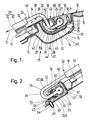
- the windshield wiper system shown in the figures is designed as a so-called horizontal wiper system and is provided on the windshield 10 of a motor vehicle 11.
- the motor vehicle 11 has, above the front window 10, a trough-like, cross-sectionally, U-shaped, cross-sectionally open, multi-walled roof frame 12 extending in the direction of the width.
- the front window 10 is conventional by means of a window seal 13 Kept wise.
- its inner wall 14 and its outer wall 15 are kept at a distance from one another by an insert 16.
- An approximately U-shaped guide frame 18, which is open in the direction of the pane 10, is held on the outer wall 15 by means of a plurality of screws, one of which is shown in FIG.
- the guide frame 18 has two legs 19 and 20 which are connected to one another by a curvature 21 which is substantially thicker than the legs 19 and 20.
- the screws 17 are screwed into coaxial bores 22, which are provided in the curvature 21 of the guide frame 18 and in the outer wall 15.
- the screws 17 are accessible through openings 23 provided in the inner wall 14 of the roof frame 12, which openings are closed by means of plugs 24.
- the guide frame 18 serves to guide a drive member (not shown) which can be driven in its longitudinal direction, on which a side view of an approximately Z-shaped driver 25 on its cylindrical head 26, the axis 27 of which extends in the direction of the width extension of the driver 25 along the Z-leg 28 thereof, is attached.
- a wiper 29 can be moved back and forth linearly over the window width via the driver 25, which has a support bracket 30 which extends over the window height and which holds two rubber wiper strips extending alongside one another in the longitudinal direction of the window wiper 31, one of which is connected to the Reference numeral 32 is shown, is shown, and which rest on the disc 10.
- the windshield wiper 29 is connected via a pin connection, not shown, which consists of a pin which extends in the longitudinal direction 31 of the windshield wiper, on the Z-leg 34 of the driver 25 which also extends in this direction 31, and a pin which is longer than the pin Support bracket 30 of the windshield wiper 29 provided blind hole, connected to the driver 25.
- a pin connection not shown, which consists of a pin which extends in the longitudinal direction 31 of the windshield wiper, on the Z-leg 34 of the driver 25 which also extends in this direction 31, and a pin which is longer than the pin Support bracket 30 of the windshield wiper 29 provided blind hole, connected to the driver 25.
- FIG. 1 also shows, in the roof frame 12 runs underneath and along the guide frame 18 and thus the drive member an approximately tubular hollow seal 35.
- This seal 35 is filled with air and accordingly acts like an air cushion. Furthermore, due to the spaced roof frame walls 14 and 15, there is still an air cushion. Therefore, there is no reason to fear a too great effect of a cold outside climate on the drive element, and thus a safe drive of the windshield wiper 29 is possible even in cold weather.
- the driver 25 protrudes essentially upwards out of the roof frame 12. It penetrates the seal 35 approximately diametrically. Accordingly, in the area where the driver 25 is located, the seal 35 has an air-filled cavity chamber 36 and 37 on both sides of its longitudinal extension, which essentially corresponds to the longitudinal direction of the wiper 31.
- the driver 25 is very well thermally insulated. Accordingly, it is to be expected that a safe windshield wiper drive is possible at all times in the climatic conditions common in Central European latitudes.
- a liquid or gaseous heating medium can also be provided in the seal 35 or can be provided for passage therethrough and / or one or more heating wires or the like can be in the seal 35 are provided so that it also acts as a heating hose. If a stationary liquid or gaseous heating medium is provided, the ends of the seal 35, not shown, must of course be sealed. A circulatory system formation in or through the seal 35 makes sense for flowing media, because this results in both energy and material savings.
- seals 35 designed in this way, or also in the case of seals without valves, condensate which may collect in the seal 35 can also be quickly removed by means of compressed air, which can be easily derived from the airstream. Accordingly, the seal 35 can also serve as a water drain hose. If such a use is provided, it makes sense to provide the sealing ends in such a position that the water is not drained off via the windshield 10 in order to avoid avoidable operation of the windshield wiper system.
- the seal 35 seals the driver 25 outstandingly against weather influences due to its hollow cylindrical shape.
- this is slit in the circumferential direction over a certain part, so that it bears here on the two longitudinal surfaces 39 and 40 of the driver 25, each with two spaced tabs 41 and 42.
- the ends of the tabs 41 lying further outside lie tightly against the longitudinal surfaces 39 and 40 of the driver 25. They are shorter than the flaps 42 located further inside.
- These flaps 42 are bent from the outer lateral surface 43 of the seal 35 towards its imaginary axis 44 into the interior of the seal and are accordingly, with long surfaces, close to the long surfaces 39 and 40 of the driver 25 .
- This special configuration of the hollow cylindrical seal 35 results in a particularly secure sealing.
- a somewhat simpler seal is provided in the entry area 45 of the driver 25 into the seal 35, which is sufficient because the guide frame 18 lies over the seal 35 here.
- the seal 35 lies closely against the longitudinal surfaces 39 and 40 of the driver 25 with two unslotted tabs 46 and 47 which are bent towards the imaginary axis 44.
- the tabs 41, 42, 46 and 47 extend over the entire length of the seal 35. At the points where the driver 25 is not currently located, the tabs 42 and the tabs 46 and 47 rest resiliently against one another.
- an extension 48 of approximately T-shaped cross section is integrally formed in the upper region of the outer lateral surface 43 of the seal 35 and extends over the entire length of the seal 35.
- the seal 35 has been inserted into a correspondingly shaped, open-ended groove which is embedded in the end of the outer leg 20 of the guide frame 18, which is made of a less elastic material than the seal 35, but just like this one noise-reducing material is made. Because of the material elasticity of the extension 48 and the guide frame 18, there is therefore a latching connection between these parts 48 and 18 and thus between the seal 35 and the guide frame 18.
- an essentially rectangular strip 49 is formed on the seal 35 in the rear region of the outer lateral surface 43 of the seal 35 and extends over its entire length. This strip 49 engages behind the inner leg 19 of the guide frame 18. Overall, noises arising from the seal 35 and the guide frame 18 in the windshield wiper drive are substantially damped. The driver of the motor vehicle 11 is accordingly not unnecessarily distracted from the traffic situation.
- the windshield wiper system Due to the recessed arrangement of windshield wiper system elements in the roof frame 12 of the motor vehicle described at the beginning, the windshield wiper system also looks elegant. This is particularly helped by the fact that both the outer lateral surface 43 of the seal 35 and the outer surface 50 of the guide frame 18 run in the same plane as the tub rim 51 formed by the roof frame 12.
- the windshield wiper 29 is fastened at its lower end 52 to a leg 53 of a driver 54 which is approximately U-shaped in a side view.
- a driver 54 which is approximately U-shaped in a side view.
- This has a cylindrical head 56 extending along its other leg 55, the axis 57 of which extends in the direction of the width of the driver 54.
- the wiper 29 is connected to the same drive member as with the other driver 25.
- the drive member and the driver 53 are here in a extending in the width direction of the motor vehicle 11, made of a noise-damping, elastic material 58, which is designed similarly to the guide frame 18 described above and has two legs 59 and 60 which are connected to one another by a curve 61.
- the curve 61 is lined with a sliding insert 62.
- the guide frame 58 is fastened to a body section 63 of the motor vehicle 11 which is U-shaped in cross section and runs just below the window 10.
- a body section 63 of the motor vehicle 11 which is U-shaped in cross section and runs just below the window 10.
- several screws are used, one of which is shown in FIG. 2, which is designated by the reference number 64.
- the screws 64 are screwed into coaxial bores 65 which are provided in the leg 59 and in the body section 63.
- the screws 64 are accessible from the outside.
- a seal 67 is provided in the outlet area 66 of the driver 54 for the lower end 52 of the wiper 29.
- this seal 67 is simpler than the seal 35 described above. It consists only of two strips 68 and 69 of elastic material arranged opposite one another. The strips 68 and 69 are as long as the guide frame 58. In cross section they are approximately T-shaped.
- the strips 68 and 69 are fastened in grooves which are embedded in the inner sides of the legs 59 and 60 of the guide frame 58.
- the strips 68 and 69 have been inserted in the longitudinal direction into the open grooves. Because of the material elasticity of strips 68, 69 and guide frame 58, there are latching connections between these parts 68 and 58 or 69 and 58. Otherwise, the strips 68 and 69 lie close to the longitudinal surfaces 71 and 72 of the driver leg 55. At the points where the driver 54 is not currently located, the strips 68 and 69 resiliently abut each other. This ensures an excellent seal of the driver 54 and the drive member against the weather.
- the described fastening and guiding of the wiper 29 at both ends 33 and 52 is particularly secure.
- a pin connection is provided at the top 33 of the wiper 29 and Driver 25 . This enables mutual correct positioning between the windshield wipers 29 and the driver 25 during their assembly and thus the avoidance of a negative influence of manufacturing-related tolerances of the windshield wiper system parts 25 and 54 or the windshield 10.
- the double-ended guidance of the windshield wiper 29 ensures that it cannot be lifted undesirably from the wind from the windshield 10 even at very high vehicle speeds.
- the windshield wiper system need not necessarily be designed as a horizontal wiper system. It can also be designed as a vertical wiper system. Then 10 seals should be provided on both sides of the disc, which are identical or similar to the seal 35.
- the use of the windshield wiper system is not restricted to motor vehicles. It can also be used on buildings. Since noise insulation is less important here than in motor vehicles, the guide frame and / or the seal does not necessarily have to consist of noise insulation material.
Landscapes
- Engineering & Computer Science (AREA)
- Mechanical Engineering (AREA)
- Body Structure For Vehicles (AREA)
- Seal Device For Vehicle (AREA)
Claims (29)
Applications Claiming Priority (2)
| Application Number | Priority Date | Filing Date | Title |
|---|---|---|---|
| DE3714224 | 1987-04-29 | ||
| DE19873714224 DE3714224A1 (de) | 1987-04-29 | 1987-04-29 | Scheibenwischeranlage |
Publications (2)
| Publication Number | Publication Date |
|---|---|
| EP0288886A1 EP0288886A1 (fr) | 1988-11-02 |
| EP0288886B1 true EP0288886B1 (fr) | 1990-10-17 |
Family
ID=6326481
Family Applications (1)
| Application Number | Title | Priority Date | Filing Date |
|---|---|---|---|
| EP88106284A Expired - Lifetime EP0288886B1 (fr) | 1987-04-29 | 1988-04-20 | Agencement d'essuie-glace |
Country Status (6)
| Country | Link |
|---|---|
| US (1) | US5046216A (fr) |
| EP (1) | EP0288886B1 (fr) |
| JP (1) | JPH01503531A (fr) |
| DE (1) | DE3714224A1 (fr) |
| ES (1) | ES2018861B3 (fr) |
| WO (1) | WO1988008382A1 (fr) |
Families Citing this family (11)
| Publication number | Priority date | Publication date | Assignee | Title |
|---|---|---|---|---|
| FR2649370B1 (fr) * | 1989-07-05 | 1994-10-28 | Chausson Usines Sa | Dispositif d'essuie-glace pour vehicules |
| FR2734222B1 (fr) * | 1995-05-17 | 1997-07-04 | Valeo Systemes Dessuyage | Installation d'essuie-glace du type a balayage alterne comportant des moyens perfectionnes d'etancheite |
| US5979796A (en) * | 1996-12-18 | 1999-11-09 | Valeo, Inc. | Heated windshield wiper washer nozzle system and method |
| US5957384A (en) * | 1997-08-26 | 1999-09-28 | Lansinger; Jere Rask | Windshield heated wiping system |
| FR2801017B1 (fr) | 1999-11-17 | 2002-01-04 | Valeo Systemes Dessuyage | Mecanisme d'essuie-glace a balayage lineaire alterne comportant un rail de guidage perfectionne |
| FR2821410B1 (fr) * | 2001-02-26 | 2003-07-04 | Renault | Joint d'etancheite, procedes pour fabriquer ce joint, et utilisation de ce joint dans un dispositif d'essuie-glace du type a balayage lineaire |
| DE10255875A1 (de) * | 2002-11-29 | 2004-06-09 | Bayerische Motoren Werke Ag | Linear-Scheibenwischer |
| US7395576B2 (en) * | 2004-07-07 | 2008-07-08 | Deere & Company | Wiper opening cover |
| US7797786B2 (en) * | 2006-04-14 | 2010-09-21 | Gpv, L.L.C. | Wiper system for vision block array in vehicles |
| US8925620B2 (en) | 2008-08-18 | 2015-01-06 | Tsm Corporation | Windshield washer fluid heater |
| US8550147B2 (en) | 2008-08-18 | 2013-10-08 | Clear Vision Associates, Llc | Windshield washer fluid heater and system |
Family Cites Families (15)
| Publication number | Priority date | Publication date | Assignee | Title |
|---|---|---|---|---|
| GB184461A (en) * | 1921-08-09 | 1923-06-28 | Louis Theophile Couty | Improved life-float and structure for gunnery practice on the high seas, applicable as a preventive against sea-sickness |
| US1644545A (en) * | 1921-10-04 | 1927-10-04 | Harry C Robertson | Power-operated window-cleaning device |
| US1490168A (en) * | 1923-01-10 | 1924-04-15 | James H Ford | Windshield heater |
| US1506004A (en) * | 1923-01-26 | 1924-08-26 | Koenigsberg Kurt | Signal for automobiles |
| US1672136A (en) * | 1927-05-20 | 1928-06-05 | Gus R Scott | Windshield cleaner |
| US1828410A (en) * | 1929-03-23 | 1931-10-20 | Delco Remy Corp | Windshield cleaner |
| US1871987A (en) * | 1929-03-23 | 1932-08-16 | Delco Remy Corp | Windshield wiper |
| US1841734A (en) * | 1930-03-20 | 1932-01-19 | Trico Products Corp | Windshield cleaner |
| US2253029A (en) * | 1939-06-14 | 1941-08-19 | Frederick D Hart | Windshield wiper |
| DE947532C (de) * | 1953-07-30 | 1956-08-16 | Karl Fischer | Scheibenwischer fuer Kraftfahrzeuge |
| AT184461B (de) * | 1954-07-02 | 1956-01-25 | Alois Dr Culen | Einrichtung zum Wischen von Flächen, insbesondere Scheibenwischer für Fahrzeuge aller Art |
| US2785429A (en) * | 1955-06-02 | 1957-03-19 | Maxwell I Walters | Windshield wiper mechanisms |
| GB887114A (en) * | 1959-01-14 | 1962-01-17 | Wynn Developments Ltd | Improvements in window or windscreen wiper mechanisms |
| DE1093236B (de) * | 1959-02-09 | 1960-11-17 | Rolf Depping | Scheibenwischer, insbesondere fuer Kraftfahrzeuge |
| US3623182A (en) * | 1970-08-27 | 1971-11-30 | Gen Motors Corp | Transverse wiping apparatus having park latch park mechanism |
-
1987
- 1987-04-29 DE DE19873714224 patent/DE3714224A1/de not_active Withdrawn
-
1988
- 1988-04-20 JP JP63503328A patent/JPH01503531A/ja active Pending
- 1988-04-20 EP EP88106284A patent/EP0288886B1/fr not_active Expired - Lifetime
- 1988-04-20 US US07/294,633 patent/US5046216A/en not_active Expired - Fee Related
- 1988-04-20 ES ES88106284T patent/ES2018861B3/es not_active Expired - Lifetime
- 1988-04-20 WO PCT/EP1988/000332 patent/WO1988008382A1/fr not_active Ceased
Also Published As
| Publication number | Publication date |
|---|---|
| JPH01503531A (ja) | 1989-11-30 |
| EP0288886A1 (fr) | 1988-11-02 |
| DE3714224A1 (de) | 1988-11-17 |
| US5046216A (en) | 1991-09-10 |
| ES2018861B3 (es) | 1991-05-16 |
| WO1988008382A1 (fr) | 1988-11-03 |
Similar Documents
| Publication | Publication Date | Title |
|---|---|---|
| EP0288886B1 (fr) | Agencement d'essuie-glace | |
| EP1375220B1 (fr) | Store avec guidage anti-cliquetis | |
| EP1666291B1 (fr) | Store à enrouler de fenêtre avec montage simplifié | |
| DE102015109862A1 (de) | Fahrzeugdach mit Rolloanordnung | |
| EP0509439B1 (fr) | Construction de toit pour véhicules | |
| WO1995029826A1 (fr) | Deflecteur pour balai d'essuie-glace | |
| DE102007019858A1 (de) | Dachfensterrollo mit vorgespannten Gleitern | |
| DE3836687C2 (de) | Dachzierleiste für ein Kraftfahrzeug | |
| DE4427196A1 (de) | Luftleitvorrichtung im Heckbereich eines Kraftfahrzeuges | |
| DE102019114304A1 (de) | Fahrzeug mit einer Dichtungsanordnung | |
| DE3118559C2 (de) | Fensterseitenwand für Personenbeförderungsfahrzeuge | |
| EP0061658B1 (fr) | Dispositif d'aération | |
| DE4310879C2 (de) | Kraftfahrzeug, insbesondere Personenkraftwagen | |
| DE202006018811U1 (de) | Steckverbinder | |
| EP0936138A2 (fr) | Fenêtre à double vitrage pour la cabine d'un aéronef | |
| DE3924035C1 (fr) | ||
| DE4017196C1 (en) | Sealing strip for car rear window - comprises H=section strip, one side of which forms water-removing gutter | |
| DE19948223B4 (de) | Fahrgastzelle eines Fahrzeugs | |
| DE3419901A1 (de) | Einbausatz fuer schiebedaecher, insbesondere oberfirst-schiebedaecher | |
| WO1997047488A1 (fr) | Buse d'aeration pour vehicules a moteur | |
| DE20211463U1 (de) | In die Armaturentafel eines Kraftfahrzeuges einbaubare Lüftungsdüse | |
| DE2610731C3 (de) | Einrichtung zur Entlüftung eines Kraftfahrzeuges, insbesondere Personenkraftwagens | |
| DE202007015435U1 (de) | Dachfensterrollo mit vorgespannten Gleitern | |
| EP4667251A1 (fr) | Système de cadre adaptateur pour un agencement côté intérieur de véhicule sur une fenêtre de cadre d'un véhicule de transport | |
| DE102018220840B4 (de) | Kraftfahrzeugkarosserie mit einer Scheibenanordnung |
Legal Events
| Date | Code | Title | Description |
|---|---|---|---|
| PUAI | Public reference made under article 153(3) epc to a published international application that has entered the european phase |
Free format text: ORIGINAL CODE: 0009012 |
|
| 17P | Request for examination filed |
Effective date: 19880831 |
|
| AK | Designated contracting states |
Kind code of ref document: A1 Designated state(s): ES FR GB IT SE |
|
| 17Q | First examination report despatched |
Effective date: 19900116 |
|
| GRAA | (expected) grant |
Free format text: ORIGINAL CODE: 0009210 |
|
| AK | Designated contracting states |
Kind code of ref document: B1 Designated state(s): ES FR GB IT SE |
|
| ITF | It: translation for a ep patent filed | ||
| ET | Fr: translation filed | ||
| GBT | Gb: translation of ep patent filed (gb section 77(6)(a)/1977) | ||
| PLBE | No opposition filed within time limit |
Free format text: ORIGINAL CODE: 0009261 |
|
| STAA | Information on the status of an ep patent application or granted ep patent |
Free format text: STATUS: NO OPPOSITION FILED WITHIN TIME LIMIT |
|
| 26N | No opposition filed | ||
| PGFP | Annual fee paid to national office [announced via postgrant information from national office to epo] |
Ref country code: GB Payment date: 19920318 Year of fee payment: 5 |
|
| PGFP | Annual fee paid to national office [announced via postgrant information from national office to epo] |
Ref country code: SE Payment date: 19920428 Year of fee payment: 5 |
|
| PGFP | Annual fee paid to national office [announced via postgrant information from national office to epo] |
Ref country code: FR Payment date: 19920429 Year of fee payment: 5 |
|
| ITTA | It: last paid annual fee | ||
| PG25 | Lapsed in a contracting state [announced via postgrant information from national office to epo] |
Ref country code: GB Effective date: 19930420 |
|
| PG25 | Lapsed in a contracting state [announced via postgrant information from national office to epo] |
Ref country code: SE Effective date: 19930421 |
|
| PGFP | Annual fee paid to national office [announced via postgrant information from national office to epo] |
Ref country code: ES Payment date: 19930421 Year of fee payment: 6 |
|
| GBPC | Gb: european patent ceased through non-payment of renewal fee |
Effective date: 19930420 |
|
| PG25 | Lapsed in a contracting state [announced via postgrant information from national office to epo] |
Ref country code: FR Effective date: 19931229 |
|
| REG | Reference to a national code |
Ref country code: FR Ref legal event code: ST |
|
| PG25 | Lapsed in a contracting state [announced via postgrant information from national office to epo] |
Ref country code: ES Free format text: LAPSE BECAUSE OF NON-PAYMENT OF DUE FEES Effective date: 19940421 |
|
| EUG | Se: european patent has lapsed |
Ref document number: 88106284.8 Effective date: 19931110 |
|
| REG | Reference to a national code |
Ref country code: ES Ref legal event code: FD2A Effective date: 19990301 |
|
| PG25 | Lapsed in a contracting state [announced via postgrant information from national office to epo] |
Ref country code: IT Free format text: LAPSE BECAUSE OF NON-PAYMENT OF DUE FEES;WARNING: LAPSES OF ITALIAN PATENTS WITH EFFECTIVE DATE BEFORE 2007 MAY HAVE OCCURRED AT ANY TIME BEFORE 2007. THE CORRECT EFFECTIVE DATE MAY BE DIFFERENT FROM THE ONE RECORDED. Effective date: 20050420 |